EP4328559A2 - Capteur de déplacement utilisant une interférence de réseau de ronchi - Google Patents
Capteur de déplacement utilisant une interférence de réseau de ronchi Download PDFInfo
- Publication number
- EP4328559A2 EP4328559A2 EP23214490.7A EP23214490A EP4328559A2 EP 4328559 A2 EP4328559 A2 EP 4328559A2 EP 23214490 A EP23214490 A EP 23214490A EP 4328559 A2 EP4328559 A2 EP 4328559A2
- Authority
- EP
- European Patent Office
- Prior art keywords
- load cell
- post
- hollow interior
- grating film
- interior section
- Prior art date
- Legal status (The legal status is an assumption and is not a legal conclusion. Google has not performed a legal analysis and makes no representation as to the accuracy of the status listed.)
- Withdrawn
Links
Images







Classifications
-
- G—PHYSICS
- G01—MEASURING; TESTING
- G01L—MEASURING FORCE, STRESS, TORQUE, WORK, MECHANICAL POWER, MECHANICAL EFFICIENCY, OR FLUID PRESSURE
- G01L1/00—Measuring force or stress, in general
- G01L1/24—Measuring force or stress, in general by measuring variations of optical properties of material when it is stressed, e.g. by photoelastic stress analysis using infrared, visible light, ultraviolet
-
- G—PHYSICS
- G01—MEASURING; TESTING
- G01L—MEASURING FORCE, STRESS, TORQUE, WORK, MECHANICAL POWER, MECHANICAL EFFICIENCY, OR FLUID PRESSURE
- G01L1/00—Measuring force or stress, in general
- G01L1/20—Measuring force or stress, in general by measuring variations in ohmic resistance of solid materials or of electrically-conductive fluids; by making use of electrokinetic cells, i.e. liquid-containing cells wherein an electrical potential is produced or varied upon the application of stress
- G01L1/22—Measuring force or stress, in general by measuring variations in ohmic resistance of solid materials or of electrically-conductive fluids; by making use of electrokinetic cells, i.e. liquid-containing cells wherein an electrical potential is produced or varied upon the application of stress using resistance strain gauges
- G01L1/2206—Special supports with preselected places to mount the resistance strain gauges; Mounting of supports
-
- G—PHYSICS
- G01—MEASURING; TESTING
- G01G—WEIGHING
- G01G1/00—Weighing apparatus involving the use of a counterweight or other counterbalancing mass
-
- G—PHYSICS
- G01—MEASURING; TESTING
- G01G—WEIGHING
- G01G19/00—Weighing apparatus or methods adapted for special purposes not provided for in the preceding groups
- G01G19/08—Weighing apparatus or methods adapted for special purposes not provided for in the preceding groups for incorporation in vehicles
-
- G—PHYSICS
- G01—MEASURING; TESTING
- G01G—WEIGHING
- G01G21/00—Details of weighing apparatus
- G01G21/23—Support or suspension of weighing platforms
Definitions
- a fifth wheel imparts forces that displace the mounting apparatus pivotally supporting the fifth wheel onto a support structure of a trailer.
- An apparatus is needed to measure the displacement.
- a load cell to measure displacements transferred by a fifth wheel to the load cell includes: an elongated mounting base portion configured to attach to a support structure of a tractor, a coupling portion configured to pivotally support a fifth wheel, a middle portion disposed above the elongated mounting base portion and below the coupling portion, the middle portion including a hollow interior section with an opening into the hollow interior section, and a post extending from the elongated mounting base portion and protruding into the hollow interior section of the middle portion.
- Variations of the first aspect of the disclosure can include any of the following features:
- the terms “below,” “upward,” “forward,” “above,” and derivatives thereof, shall relate to the disclosure as oriented in FIG. 1 , where certain relative terms such as lateral, longitudinal, and vertical are explicitly illustrated. However, it is to be understood that the disclosure may assume various alternative orientations, except where expressly specified to the contrary. It is also to be understood that the specific devices and processes illustrated in the attached drawings, and described in the following specification, are exemplary embodiments of the inventive concepts defined in the appended claims. Hence, specific dimensions and other physical characteristics relating to the embodiments disclosed herein are not to be considered as limiting, unless the claims expressly state otherwise.
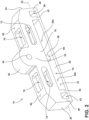
- a load cell 10 to measure displacements transferred by a fifth wheel 12 is illustrated in context, with the load cell 10 supported by a support structure 14 (e.g., a frame rail) attached to a tractor or semi-truck (not shown) and the load cell 10 pivotally supporting the fifth wheel 12.
- a second load cell (not shown), identical in all respects to the load cell 10, may be supported by another support structure 16 (e.g., another frame rail).
- the second load cell may be pivotally supporting the fifth wheel 12.
- the load cell 10 utilizes one or more optical array sensors and Ronchi grating films to determine displacements.
- the load cell 10 includes a first lateral side 18 and a second lateral side 20 on the opposite side of the load cell 10 as the first lateral side 18.
- the load cell 10 further comprises a longitudinal midline 22 between the first lateral side 18 and the second lateral side 20.
- the load cell 10 further comprises a first longitudinal side 24 and a second longitudinal side 26 on the opposite side of the load cell 10 as the first longitudinal side 24.
- the load cell 10 includes an elongated mounting base portion 28.
- the elongated mounting base portion 28 is configured to attach to the support structure 14 of the tractor.
- the elongated mounting base portion 28 may comprise mounting apertures 30a and 30b spaced to match apertures (not shown) disposed on the support structure 14, through which a fastener (not shown) can extend, thus allowing the attachment of the elongated mounting base portion 28 to the support structure 14.
- the elongated mounting base portion 28 further includes a planar top surface 32 and a planar bottom surface 34 parallel to and below the planar top surface 32.
- the mounting apertures 30a and 30b extend through the elongated mounting base portion 28 from the planar top surface 32 to the planar bottom surface 34.
- the load cell 10 further includes a coupling portion 36.
- the coupling portion 36 is configured to pivotally support the fifth wheel 12.
- the coupling portion 36 includes an aperture 38, which is positioned to match an aperture (not shown) on the fifth wheel 12 and through which a pin or fastener (not shown) can extend to couple the coupling portion 36 and the fifth wheel 12.
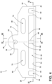
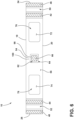
- the aperture 38 has a centerline 40 (see, e.g., FIGS. 4 and 5 ), which represents the axis about which the fifth wheel 12 pivots.
- the aperture 38 extends through the coupling portion 36 from the first lateral side 18 through to the second lateral side 20.
- the load cell 10 further includes a first interior column 42 and a second interior column 44.
- the first interior column 42 is disposed near the first longitudinal side 24 of the load cell 10.
- the first interior column 42 extends laterally from the first lateral side 18 to the second lateral side 20 of the load cell 10.
- the first interior column 42 extends vertically upward from the elongated mounting base portion 28.
- the second interior column 44 is disposed near the second longitudinal side 26 of the load cell 10.
- the second interior column 44 extends laterally from the first lateral side 18 to the second lateral side 20 of the load cell 10.
- the second interior column 44 extends vertically upward from the elongated mounting base portion 28.
- the load cell 10 further includes a first edge column 46.
- the first edge column 46 terminates with the first longitudinal side 24. In other words, the forward longitudinal surface of the first edge column 46 is the first longitudinal side 24.
- the first edge column 46 is disposed near the first interior column 42.
- the first edge column 46 extends laterally from the first lateral side 18 to the second lateral side 20.
- the first edge column 46 extends vertically upward from the elongated mounting base portion 28.
- the load cell 10 further includes a second edge column 48.
- the second edge column 48 terminates with the second longitudinal side 26. In other words, the rearward longitudinal surface of the second edge column 48 is the second longitudinal side 26.
- the second edge column 48 is disposed near the second interior column 44.
- the second edge column 48 extends laterally from the first lateral side 18 to the second lateral side 20.
- the second edge column 48 extends vertically upward from the elongated mounting base portion 28.
- the load cell 10 further includes a first edge void space 50 and a second edge void space 52.
- the first edge void space 50 extends from the first lateral side 18 through to the second lateral side 20 and is disposed between the first edge column 46 and the first interior column 42.
- the second edge void space 52 extends from the first lateral side 18 through to the second lateral side 20 and is disposed between the second edge column 48 and the second interior column 44.
- the load cell 10 further includes a middle portion 54 disposed above the elongated mounting base portion 28 and below the coupling portion 36.
- the middle portion 54 includes a planar bottom surface 56.
- the planar bottom surface 56 is parallel to the planar top surface 32 of the elongated mounting base portion 28.
- the planar bottom surface 56 extends longitudinally from the first interior column 42 to the second interior column 44. In other words, the first interior column 42 and the second interior column 44 are disposed between the planar bottom surface 56 of the middle portion 54 and the planar top surface 32 of the elongated mounting base portion 28.
- the planar bottom surface 56 extends laterally from the first lateral side 18 to the second lateral side 20.
- the middle portion 54 further includes a first planar top surface 58 and a second planar top surface 60.
- the first planar top surface 58 is disposed between the first longitudinal side 24 and the coupling portion 36.
- the first planar top surface 58 is parallel to the planar bottom surface 56 of the middle portion 54.
- the second planar top surface 60 is disposed between the second longitudinal side 26 and the coupling portion 36.
- the second planar top surface 60 is parallel to the planar bottom surface 56 of the middle portion 54.
- the middle portion 54 further includes a hollow interior section 62.
- the middle portion 54 further includes an opening 64 into the hollow interior section 62.
- the hollow interior section 62 is disposed between the centerline 40 of the aperture 38 of the coupling portion 36 and the elongated mounting base portion 28.
- the load cell 10 further includes a post 66 that extends vertically from the elongated mounting base portion 28. More specifically, in this embodiment, the post 66 extends orthogonally vertically from the planar top surface 32 of the elongated mounting base portion 28. The post 66 protrudes into the hollow interior section 62 of the middle portion 54. The post 66 is disposed between the centerline 40 of the aperture 38 of the coupling portion 36 and the elongated mounting base portion 28. The post 66 has a vertical centerline 68. The vertical centerline 68 of the post 66 and the centerline 40 of the aperture 38 of the coupling portion 36 intersect at an orthogonal angle. The purpose of the post 66 is discussed further below.
- the load cell 10 further includes a middle void space 70.
- the middle void space 70 extends from the first lateral side 18 through to the second lateral side 20, except for the post 66. In other words, the post 66 extends up through the middle void space 70.
- the middle void space 70 is disposed between the first interior column 42 and the second interior column 44.
- the middle portion 54 further includes a first lateral void space 72.
- the first lateral void space 72 is disposed longitudinally between the first longitudinal side 24 and the hollow interior section 62.
- the first lateral void space 72 is disposed vertically between the first planar top surface 58 and the planar bottom surface 56 of the middle portion 54.
- the first lateral void space 72 extends laterally from the first lateral side 18 through to the second lateral side 20.
- the middle portion 54 further includes a second lateral void space 74.
- the second lateral void space 74 is disposed longitudinally between the second longitudinal side 26 and hollow interior section 62.
- the second lateral void space 74 is disposed vertically between the second planar top surface 60 and the planar bottom surface 56 of the middle portion 54.
- the second lateral void space 74 extends laterally from the first lateral side 18 through to the second lateral side 20.
- the middle portion 54 further includes a first vertical void space 76.
- the first vertical void space 76 is disposed longitudinally between the first longitudinal side 24 and the hollow interior section 62.
- the first vertical void space 76 extends vertically from the planar bottom surface 56 of the middle portion 54 through to the first planar top surface 58.
- the first vertical void space 76 is contiguous with the first lateral void space 72.
- the middle portion 54 further includes a second vertical void space 78.
- the second vertical void space 78 is disposed longitudinally between the second longitudinal side 26 and the hollow interior section 62.
- the second vertical void space 78 extends vertically from the planar bottom surface 56 of the middle portion 54 through to the first planar top surface 58.
- the second vertical void space 78 is contiguous with the second lateral void space 74.
- the first vertical void space 76, the first lateral void space 72, the first edge void space 50, the middle void space 70, the second edge void space 52, the second lateral void space 74, and the second vertical void space 78 all serve to isolate the displacement forces that the fifth wheel 12 imparts on the load cell 10, such that the displacement forces can be converted into component displacements (lateral, longitudinal, and vertical) with as little cross-talk as possible.
- the post 66 extending from the elongated mounting base portion 28, which is attached to the support structure 14, remains relatively motionless, while remainder of the load cell 10, especially the middle portion 54 surrounding the hollow interior section 62, is displaced in the lateral, longitudinal, and vertical directions. Measuring the amount of displacement of the middle portion 54 relative to the post 66, is now discussed.
- the load cell 10 further comprises a first optical array sensor 80 (see particularly FIGS. 7 and 9 ).
- An example of such an optical array sensor is the IC linear sensor array 256X1, part number TSL1402-R-ND, manufactured by AMS, however, other optical array sensors suitable for the applications as disclosed herein may also be utilized.
- An optical sensor array can include an array of photodiodes, each the size of one pixel, and each producing an output voltage that depends on the intensity of light impinging upon the photodiode. The greater the light intensity reaching the photodiode, the greater the output voltage.
- the first optical array sensor 80 is attached to the post 66 within the hollow interior section 62 of the middle portion 54.
- the first optical array sensor 80 includes an array of photodiodes 82 that are arranged vertically.
- individual photo diodes, phot resistive elements, or other optical sensors may be utilized.
- the load cell 10 further includes a first immobile grating film 84 applied over the first optical array sensor 80.
- the first immobile grating film 84 is "immobile" in the sense that it is interconnected with the post 66, which, as described above, is designed to be relatively stationary while the fifth wheel 12 is imparting forces to the load cell 10.
- the first immobile grating film 84 like all other grating films discussed below, comprises a transparent film 86 with evenly spaced grid of lines 88 printed thereon. An incoming light ray (not shown) that encounters one of the lines of the grid of lines 88 either bounces off the line or is absorbed.
- the transparent film 86 with the grid of lines 88 is sometimes referred to as a Ronchi grid or a Ronchi grating.
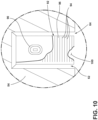
- the load cell 10 further includes a first light source 90 (see particularly FIGS. 8 and 10 ) disposed within the hollow interior section 62.
- the first light source 90 can be an LED, a light bar, a filament bulb, among other options.
- the load cell 10 further includes a first mobile grating film 92 interconnected with the middle portion 54 within the hollow interior section 62.
- the first mobile grating film 92 is applied over the first light source 90.
- the first mobile grating film 92 is "mobile" in the sense that it is not attached to the post 66, but rather to the middle portion 54 within the hollow interior section 62, which moves as a result of the forces applied to the load cell 10 from the fifth wheel 12.
- the first mobile grating film 92 is similar to the first immobile grating film 84 in that the first mobile grating film 92 likewise comprises a grid of lines 94 printed on a transparent film 96. The number of lines and the spacing of the lines of the grid of lines 94 on the first mobile grating film 92 will differ from the number of lines and the spacing of the lines of the grid of lines 88 on the first immobile grating film 84.
- the first light source 90 emits light (not shown) towards the first optical array sensor 80.
- the light transmits through the first mobile grating film 92, then through the first immobile grating film 84, and then to the first optical array sensor 80.
- the first mobile grating film 92 and the first immobile grating film 84 cooperate to vary the intensity of the light emitted by the first light source 90 that the first optical array sensor 80 perceives.
- One photodiode 82 receives light of a certain intensity and an adjacent photodiode 82 may receive light of an intensity of a greater or lesser magnitude.
- the first mobile grating film 92 and the first immobile grating film 84 can cause the first optical array sensor 80 to perceive an interference pattern, greater light intensity changing to lesser light intensity changing to greater light intensity, as a function of position along the first optical array sensor 80, or numerous such patterns occurring at a regular interval (called "frequency").
- Each photodiode 82 outputs a voltage reflecting this light intensity, and the light intensity varies as a function of position along the first optical array sensor 80.
- the output voltage that each photodiode 82 outputs can be recorded and manipulated.
- both the first immobile grating film 84 and the first mobile grating film 92 include a grid of lines 88, 94 respectively.
- both the grid of lines 88 of first immobile grating film 84 and the grid of lines 94 of the first mobile grating film 92 are arranged horizontally, while, as mentioned, the photodiodes 82 of the first optical sensor array 80 are arranged vertically.
- either the grid of lines 88 of the first immobile grating film 84 or the grid of lines 94 of the first mobile grating film 92 are arranged horizontally while the other grid of lines 88 or 94 are arranged other than horizontally (such as diagonally).
- the post 66 further includes a first surface 98 (see particularly FIGS. 7 and 9 ).
- the first surface 98 of the post 66 forms a plane parallel with the longitudinal midline 22 of the load cell 10.
- the first surface 98 of the post 66 faces the middle portion 54.
- the middle portion 54 likewise includes a first surface 100 (see particularly FIG. 10 ).
- the first surface 100 of the middle portion 54 likewise forms a plane parallel with a longitudinal midline 22 of the load cell 10 and thus is parallel with the first surface 98 of the post 66.
- the first surface 98 of the middle portion 54 is accessible from the hollow interior section 62.
- the first surface 100 of the middle portion 54 faces the first surface 98 of the post 66.
- the first optical array sensor 80 is affixed to the first surface 98 of the post 66.
- the first light source 90 is affixed to the first surface 100 of the middle portion 54.
- the first immobile grating film 84 covering the first optical array sensor 80 on the first surface 98 of the post 66, faces the first mobile grating film 92, which is covering the first light source 90.
- the first light source 90 is placed on the first surface 98 of the post 66 adjacent the first optical array sensor 80, and the first mobile grating film 92 is affixed directly to the first surface 100 of the middle portion 54 (which first surface 100 is a reflective surface).
- the first light source 90 emits light, which either is absorbed by a line of the grid of lines 94 of the first mobile grating film 92 or is reflected off the first surface 100 of the middle portion 54. Light reflected off the first surface 100 of the middle portion 54 is then either absorbed by a line of the grid of lines 88 of the first immobile grating film 84 or transferred through the transparent film 86 and perceived by a photodiode 82 of the first optical array sensor 80.
- the first mobile grating film 92 and the first immobile grating film 84 affect the light emitted by the first light source 90 in the same manner, as described above, and the photodiodes 82 of the first optical array sensor 80 produce an output voltage as a function of light intensity, which changes as the force of the fifth wheel 12 moves the first mobile grating film 92 relative to the first immobile grating film 84.
- the post 66 further includes a second surface 102 (see particularly FIG. 11 ), which forms a plane parallel with the centerline 40 of the aperture 38 of the coupling portion 36.
- the centerline 40 of the aperture 38 of the coupling portion 36 is in the lateral direction and the plane formed by the second surface 102 is also laterally disposed.
- the load cell 10 further includes a second optical array sensor 104.
- the second optical array sensor 104 is also attached to the post 66 within the hollow interior section 62 of the middle portion 54.
- the second optical array sensor 104 is affixed to the second surface 102 of the post 66.
- the second optical array sensor 104 includes an array of photodiodes 106 that are arranged laterally. That is, horizontally across the post 66.
- the load cell 10 further includes a second immobile grating film 108 applied over the second optical array sensor 104.
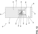
- the middle portion 54 of the load cell 10 further includes a second surface 110 (see particularly FIG. 12 ).
- the second surface 110 also forms a plane parallel with the centerline 40 of the aperture 38 of the coupling portion 36.
- the second surface 110 is accessible from the hollow interior section 62 and thus faces the post 66, specifically the second surface 102 of the post 66.
- the load cell 10 further includes a second light source 112 disposed within the hollow interior section 62. In this embodiment, the second light source 112 is affixed to the second surface 110 of the middle portion 54.
- the load cell 10 further includes a second mobile grating film 114 interconnected with the middle portion 54 within the hollow interior section 62.
- the second mobile grating film 114 is applied over the second light source 112 and thus faces the second immobile grating film 108 applied over the second optical array sensor 104.
- the second light source 112 emits light (not shown) towards the second optical array sensor 104.
- the light transmits through the second mobile grating film 114, then through the second immobile grating film 108, and then to the second optical array sensor 104.
- Both the second immobile grating film 108 and the second mobile grating film 114 include a grid of lines 116, 118, respectively. At least either the grid of lines 116 of the second immobile grating film 114 or the grid of lines 118 of the second mobile grating film 114 are arranged vertically. In this embodiment, the grid of lines 116, 118 of both the second immobile grating film 108 and the second mobile grating film 114 are arranged vertically.
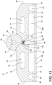
- the post 66 further includes a third surface 120 (see particularly FIG. 13 ).
- the third surface 120 forms a plane parallel with the first surface 98 of the post 66.
- the third surface 120 is disposed on the opposite side of the post 66 as the first surface 98.
- the load cell 10 further includes a third optical array sensor 122.
- the third optical array sensor 122 is attached to the post 66 within the hollow interior section 62.
- the third optical array sensor 122 is affixed to the third surface 120 of the post 66 and the third optical array sensor 122 includes an array of photodiodes 124 that are arranged horizontally.
- the load cell 10 further includes a third immobile grating film 126.
- the third immobile grating film 126 is applied over the third optical array sensor 122.
- the middle portion 54 further includes a third surface 128 (see particularly FIG. 14 ).
- the third surface 128 forms a plane parallel with the third surface 120 of the post 66.
- the third surface 128 is accessible from the hollow interior section 62.
- the third surface 128 of the middle portion 54 faces the third surface 120 of the post 66.
- the load cell 10 further includes a third light source 130.
- the third light source 130 is disposed within the hollow interior section 62.
- the third light source 130 is affixed to the third surface 128 of the middle portion 54.
- the load cell 10 further includes a third mobile grating film 132.
- the third mobile grating film 132 is interconnected with the middle portion 54 within the hollow interior section 62.
- the third mobile grating film 132 is applied over the third light source 130 and thus the third immobile grating film 126 faces the third mobile grating film 132.
- the third light source 130 emits light that transmits through the third mobile grating film 132, then through the third immobile grating film 126, and then to the third optical array sensor 122.
- Both the third immobile grating film 126 and the third mobile grating film 132 include a grid of lines 134, 136, respectively. At least either the grid of lines 134 of the first immobile grating film 126 or the grid of lines 136 of the third mobile grating film 132 are arranged vertically. In this embodiment, both the grid of lines 134 of the third immobile grating film 126 and the grid of lines 136 of the third mobile grating film 132 are arranged vertically.
- the output voltages of the first optical array sensor 80 vary primarily as a function of the vertical displacement of the middle portion 54 relative to the post 66.
- the output voltages of the second optical array sensor 104 vary primarily as a function of lateral displacement of the middle portion 54 relative to the post 66.
- the output voltages of the third optical array sensor 122 vary primarily as a function of longitudinal displacement of the middle portion 54 relative to the post 66.
- the first optical sensor array 80, the second optical sensor array 104, and the third optical sensor array 122, with the respective immobile grating films 84, 108, 126 applied over the sensor array as described above, are affixed as a pack to the top 138 of the post 66.
- the arrays 80, 104, 122 all face in the same direction as described above, and receive light from the first light source 90, second light source 112, and third light source 130 respectively, after the emitted light transmits through the first mobile grating film 92, second mobile grating film 114, and third mobile grating film 132 as described above.
- the load cell 10 may be divided into two component parts, such as divided down the longitudinal midline 22 of the load cell 10, and then welded or otherwise combined into one rigid component load cell 10.
Landscapes
- Physics & Mathematics (AREA)
- General Physics & Mathematics (AREA)
- Force Measurement Appropriate To Specific Purposes (AREA)
- Length Measuring Devices By Optical Means (AREA)
- Measurement Of Force In General (AREA)
Applications Claiming Priority (3)
| Application Number | Priority Date | Filing Date | Title |
|---|---|---|---|
| US201762572817P | 2017-10-16 | 2017-10-16 | |
| EP18868114.2A EP3698110B1 (fr) | 2017-10-16 | 2018-10-16 | Capteur de déplacement utilisant une interférence de grille de ronchi |
| PCT/IB2018/058028 WO2019077503A2 (fr) | 2017-10-16 | 2018-10-16 | Capteur de déplacement utilisant une interférence de grille de ronchi |
Related Parent Applications (2)
| Application Number | Title | Priority Date | Filing Date |
|---|---|---|---|
| EP18868114.2A Division-Into EP3698110B1 (fr) | 2017-10-16 | 2018-10-16 | Capteur de déplacement utilisant une interférence de grille de ronchi |
| EP18868114.2A Division EP3698110B1 (fr) | 2017-10-16 | 2018-10-16 | Capteur de déplacement utilisant une interférence de grille de ronchi |
Publications (2)
| Publication Number | Publication Date |
|---|---|
| EP4328559A2 true EP4328559A2 (fr) | 2024-02-28 |
| EP4328559A3 EP4328559A3 (fr) | 2024-07-24 |
Family
ID=66096984
Family Applications (2)
| Application Number | Title | Priority Date | Filing Date |
|---|---|---|---|
| EP23214490.7A Withdrawn EP4328559A3 (fr) | 2017-10-16 | 2018-10-16 | Capteur de déplacement utilisant une interférence de réseau de ronchi |
| EP18868114.2A Active EP3698110B1 (fr) | 2017-10-16 | 2018-10-16 | Capteur de déplacement utilisant une interférence de grille de ronchi |
Family Applications After (1)
| Application Number | Title | Priority Date | Filing Date |
|---|---|---|---|
| EP18868114.2A Active EP3698110B1 (fr) | 2017-10-16 | 2018-10-16 | Capteur de déplacement utilisant une interférence de grille de ronchi |
Country Status (5)
| Country | Link |
|---|---|
| US (2) | US11428589B2 (fr) |
| EP (2) | EP4328559A3 (fr) |
| CA (1) | CA3079147A1 (fr) |
| MX (1) | MX2020003595A (fr) |
| WO (1) | WO2019077503A2 (fr) |
Families Citing this family (5)
| Publication number | Priority date | Publication date | Assignee | Title |
|---|---|---|---|---|
| WO2017142844A1 (fr) * | 2016-02-19 | 2017-08-24 | Stress-Tek, Inc. | Ensemble cellule de mesure |
| WO2018151881A1 (fr) * | 2017-02-14 | 2018-08-23 | Saf-Holland, Inc. | Support de montage de cinquième roue ayant des zones d'isolation aidant à la mesure de force |
| US11428589B2 (en) | 2017-10-16 | 2022-08-30 | Saf-Holland, Inc. | Displacement sensor utilizing ronchi grating interference |
| DE102021112071A1 (de) * | 2021-05-10 | 2022-11-10 | Zf Cv Systems Global Gmbh | Verfahren zum Überwachen einer Kupplungsverbindung zwischen Teilfahrzeugen eines Fahrzeug-Gespanns sowie Fahrzeug-Gespann |
| CN119654273A (zh) * | 2022-08-01 | 2025-03-18 | 鲁利克有限责任公司 | 用于半挂式卡车的牵引单元的半挂车联轴器的半挂车联接锁的磨损环和锁定钩 |
Family Cites Families (141)
| Publication number | Priority date | Publication date | Assignee | Title |
|---|---|---|---|---|
| US2886717A (en) | 1953-03-14 | 1959-05-12 | Ferranti Ltd | Measuring apparatus |
| US2787834A (en) | 1954-02-16 | 1957-04-09 | Norman H Shoup | Grating strain gauges |
| US3283838A (en) | 1964-08-17 | 1966-11-08 | David S Fetterman | Apparatus and method for computing equivalent weight of tractor trailer vehicle |
| US3588462A (en) | 1966-12-23 | 1971-06-28 | Bausch & Lomb | Fringe interpolator and counter |
| AT288050B (de) | 1968-01-29 | 1971-02-25 | Leitz Ernst Gmbh | Einrichtung zum Messen von Längen oder Winkeln |
| US3628866A (en) | 1969-01-24 | 1971-12-21 | Bendix Corp | Noncontacting method of measuring strain |
| US3612881A (en) * | 1969-04-14 | 1971-10-12 | Cessna Aircraft Co | Relative movement detector |
| US3664187A (en) | 1970-06-03 | 1972-05-23 | Saab Scania Ab | Transducer for measuring mechanical forces |
| DE2130840A1 (de) * | 1971-06-22 | 1972-12-28 | Heidenhain Gmbh Dr Johannes | Waage |
| US3661220A (en) | 1971-11-01 | 1972-05-09 | Electro Dev Corp | Weighing device for logging trucks or the like |
| US3854540A (en) | 1973-08-03 | 1974-12-17 | G Holmstrom | Vehicle weighing means |
| US3915248A (en) | 1975-01-10 | 1975-10-28 | Owen Paelian | Weighing system |
| US3923110A (en) * | 1975-02-12 | 1975-12-02 | Leonard Sa Ets | Precision displacement measuring device for an electronic read-out platform scale |
| JPS5287061A (en) * | 1976-01-14 | 1977-07-20 | Kubota Ltd | Antiiflicker circuit for digital charge balance |
| US4044847A (en) | 1976-01-30 | 1977-08-30 | Pitney-Bowes, Inc. | Weighing system with a moire optoelectronic transducer |
| US4047585A (en) * | 1976-03-08 | 1977-09-13 | Pitney-Bowes, Inc. | Scale optical detector with spring constant variation compensator |
| US4095659A (en) * | 1976-06-10 | 1978-06-20 | Eldec Corporation | Deflection-restrained load cell for on-board vehicle weighing systems |
| US4129191A (en) * | 1977-09-26 | 1978-12-12 | Pitney-Bowes, Inc. | Optical detector which compensates for nonlinearities in a weight measuring system |
| US4329881A (en) * | 1980-02-22 | 1982-05-18 | Alden Schloss | Extremely sensitive force detector |
| US4712000A (en) * | 1983-10-21 | 1987-12-08 | Canon Kabushiki Kaisha | Rotary encoder with source-adjacent light sampling and control |
| US4641027A (en) * | 1984-12-18 | 1987-02-03 | Battelle Memorial Institute | Indicating positions |
| US4666003A (en) | 1985-09-17 | 1987-05-19 | Stress-Tek, Inc. | On-board load cell |
| DE3611337A1 (de) * | 1986-04-04 | 1987-10-22 | Deutsche Forsch Luft Raumfahrt | In einer kunststoffkugel untergebrachte, opto-elektronische anordnung |
| US4722600A (en) | 1986-10-14 | 1988-02-02 | Chiang Fu Pen | Apparatus and method for measuring strain |
| US4819051A (en) * | 1987-06-29 | 1989-04-04 | Honeywell Inc. | Compensated rotary position encoder |
| JPH01212301A (ja) | 1988-02-19 | 1989-08-25 | Toshiba Corp | ひずみセンサ |
| US4939368A (en) | 1989-04-13 | 1990-07-03 | Massachusetts Institute Of Technology | Polychromatic optical strain gauge |
| US4921059A (en) * | 1989-04-21 | 1990-05-01 | Lodec, Inc. | Load cell block and method of manufacturing the same |
| DE3935479A1 (de) | 1989-10-25 | 1991-05-02 | Pfister Gmbh | Anhaengerkupplung |
| GB2242518B (en) | 1990-03-12 | 1994-03-30 | Univ Southampton | Strain gauge |
| GB9111382D0 (en) * | 1991-05-25 | 1991-07-17 | Renishaw Metrology Ltd | Improvements in measuring probes |
| GB9209259D0 (en) | 1992-04-29 | 1992-06-17 | Bloxwich Eng | Fifth wheel coupling |
| US5490430A (en) | 1992-05-14 | 1996-02-13 | Anderson; Philip M. | Optical torque sensor utilizing change in reflectance grating line spacing |
| JPH06216426A (ja) | 1992-06-09 | 1994-08-05 | Nippondenso Co Ltd | 磁歪層形成方法およびそれを用いた歪センサ |
| US5681998A (en) | 1992-06-09 | 1997-10-28 | Yazaki Corporation | Load measuring device for a vehicle |
| DE4402529A1 (de) | 1993-02-17 | 1994-08-18 | Fischer Georg Verkehrstechnik | Anordnung von Meßmitteln an einem Sattelfahrzeug |
| DE4402526C2 (de) | 1993-02-17 | 1998-12-10 | Fischer Georg Verkehrstechnik | Anordnung von Meßmitteln an einem eine Sattelzugmaschine und einen Sattelanhänger aufweisenden Sattelfahrzeug |
| DE4402528C2 (de) | 1993-02-17 | 1996-07-04 | Fischer Georg Verkehrstechnik | Anordnung von Meßmitteln an einem Sattelfahrzeug |
| DE4402525C2 (de) | 1993-02-17 | 1998-10-29 | Fischer Georg Verkehrstechnik | Anordnung von Meßmitteln an einem eine Sattelzugmaschine und einen Sattelanhänger aufweisenden Sattelfahrzeug |
| US5387972A (en) * | 1993-03-15 | 1995-02-07 | National Research Council Of Canada | Coherent phase and frequency detection using sum-frequency mixing in non-linear waveguides |
| US5365059A (en) * | 1993-08-06 | 1994-11-15 | Bilanx Technology, Inc. | Parallel beam force measurement apparatus having an optical light sensor means |
| US5488471A (en) * | 1993-12-02 | 1996-01-30 | Mcclenahan; James W. | Sensors for vehicle alignment system and apparatus using same |
| GB9423176D0 (en) * | 1994-11-17 | 1995-01-04 | Renishaw Plc | Touch probe |
| US5777240A (en) * | 1995-08-25 | 1998-07-07 | The Montalvo Corporation | Load cell and load cell beam assembly |
| JP3163965B2 (ja) | 1995-09-27 | 2001-05-08 | 三菱自動車工業株式会社 | 磁歪式センサの構造 |
| US5847832A (en) * | 1996-03-15 | 1998-12-08 | Hughes Aircraft Company | Moire topographic measurement |
| US5714832A (en) * | 1996-03-15 | 1998-02-03 | Hughes Electronics | Miniature grating device |
| JP3246334B2 (ja) | 1996-06-04 | 2002-01-15 | 三菱自動車工業株式会社 | 車両荷重測定装置 |
| US6384908B1 (en) * | 1996-08-15 | 2002-05-07 | Go Sensors, Llc | Orientation dependent radiation source |
| US6118083A (en) | 1996-11-08 | 2000-09-12 | Creative Microsystems | Weight measurement apparatus for vehicles |
| US5811738A (en) | 1996-11-08 | 1998-09-22 | Larry D. Santi | Trunnion-mounted weight measurement apparatus |
| US5969342A (en) | 1997-05-30 | 1999-10-19 | Feng; Maria Q. | Multiplexable optical fiber displacement, strain acceleration and pressure sensors and method of operating the same |
| US5909283A (en) * | 1997-10-07 | 1999-06-01 | Eselun; Steven Albert | Linear encoder using diverging light beam diffraction |
| US6417466B2 (en) * | 1998-09-03 | 2002-07-09 | Measurement Specialties, Inc. | Load cell with bossed sensor plate for an electrical weighing scale |
| FI110210B (fi) * | 1998-12-31 | 2002-12-13 | Kibron Inc Oy | Mittauslaite pienten voimien ja siirtymien mittaamiseksi |
| GB9907643D0 (en) * | 1999-04-06 | 1999-05-26 | Renishaw Plc | Measuring probe |
| US6495774B1 (en) | 1999-04-29 | 2002-12-17 | Brian L. Pederson | Load cell holding means |
| US6587211B1 (en) | 1999-07-28 | 2003-07-01 | Creo Srl | Interferometric torque and power sensor |
| SE516661C2 (sv) * | 1999-11-12 | 2002-02-12 | Scania Cv Ab | Kopplingsanordning omfattande vändskiva |
| US6302424B1 (en) | 1999-12-09 | 2001-10-16 | Holland Hitch Company | Force-sensing fifth wheel |
| US6452485B1 (en) * | 2000-01-28 | 2002-09-17 | The Holland Group, Inc. | Electronic system for monitoring a fifth wheel hitch |
| ATE344739T1 (de) | 2000-05-25 | 2006-11-15 | Haldex Brake Corp | Sensor für ein niveauregelsystem |
| US6778236B1 (en) | 2000-06-01 | 2004-08-17 | Reveo, Inc. | Reflective liquid crystal strain gauge with aspected particles and polarization-sensitive devices |
| EP1199547A3 (fr) | 2000-10-18 | 2002-07-10 | Diessel Mobile Electronics A/S | Couplage de traction de cinquième roue avec senseur de force |
| US6487913B2 (en) | 2000-12-18 | 2002-12-03 | Eastman Kodak Company | Strain gauge with resonant light modulator |
| US6494102B2 (en) | 2001-01-12 | 2002-12-17 | Trw Inc. | Magnetostrictive stress sensor |
| US6698299B2 (en) | 2001-05-05 | 2004-03-02 | Methode Electronics, Inc. | Magnetoelastic torque sensor |
| US6600555B2 (en) * | 2001-10-15 | 2003-07-29 | Hunter Engineering Company | Apparatus and method for target identification in a vehicle wheel alignment system |
| DE10158775B4 (de) * | 2001-11-30 | 2004-05-06 | 3Dconnexion Gmbh | Anordnung zum Erfassen von Relativbewegungen oder Relativpositionen zweier Objekte |
| US20030174343A1 (en) * | 2002-03-18 | 2003-09-18 | Mitutoyo Corporation | Optical displacement sensing device with reduced sensitivity to misalignment |
| US6931940B2 (en) | 2002-10-02 | 2005-08-23 | Delphi Technologies, Inc. | Magnetostrictive strain sensor with hall effect |
| DE10246031A1 (de) * | 2002-10-02 | 2004-04-15 | 3Dconnexion Gmbh | Positions- und/oder Bewegungsfühler mit Überlastungsschutz |
| US7403294B2 (en) * | 2003-03-07 | 2008-07-22 | Boxboro Systems, Llc | Optical measurement device and method |
| DE10319319A1 (de) | 2003-04-29 | 2005-01-27 | Infineon Technologies Ag | Sensoreinrichtung mit magnetostriktivem Kraftsensor |
| US7009118B2 (en) | 2003-05-13 | 2006-03-07 | Dynamic Datum Llc | Vehicle load weighing system and load cells for such systems |
| JP4072506B2 (ja) * | 2003-05-20 | 2008-04-09 | ミネベア株式会社 | 光学式変位センサおよび外力検出装置 |
| US20040256163A1 (en) * | 2003-06-23 | 2004-12-23 | Thomson Robert K. | Optical scale |
| US7140633B2 (en) * | 2004-01-29 | 2006-11-28 | The Holland Group, Inc. | Fifth wheel mounting and cross member assembly |
| JP3914210B2 (ja) * | 2004-02-25 | 2007-05-16 | ミネベア株式会社 | 光学式変位センサおよび外力検出装置 |
| JP4035515B2 (ja) * | 2004-05-18 | 2008-01-23 | ミネベア株式会社 | 光学式変位センサおよび外力検出装置 |
| US7159890B2 (en) | 2004-10-06 | 2007-01-09 | ZF Lemförder Metallwaren AG | Trailer hitch for a motor vehicle |
| US7214893B2 (en) | 2005-02-15 | 2007-05-08 | Electric Arc Technologies, Llc | Load cell system |
| US7548155B2 (en) | 2005-02-18 | 2009-06-16 | Saf-Holland, Inc. | Fifth wheel sensor assembly |
| US20060202443A1 (en) * | 2005-03-09 | 2006-09-14 | The Holland Group, Inc. | Fifth wheel slider assembly |
| US7538310B2 (en) * | 2005-03-31 | 2009-05-26 | Sanyo Electric Co., Ltd. | Laser beam irradiation device with error position detection |
| US7202425B2 (en) * | 2005-04-13 | 2007-04-10 | The Montalvo Corporation | Under-pillow-block load cell |
| US7152491B2 (en) | 2005-04-22 | 2006-12-26 | Key Safety Systems, Inc. | Magnetostrictive vehicle weight sensor |
| US7477362B2 (en) | 2005-09-27 | 2009-01-13 | Nanyang Technological University | Moiré interferometric strain sensor |
| US7430491B2 (en) | 2005-10-11 | 2008-09-30 | International Truck Intecllectual Property Company, Llc | Tractor-trailer having self-contained apparatus on-board tractor for estimating trailer weight |
| JP4312192B2 (ja) * | 2005-11-02 | 2009-08-12 | ミネベア株式会社 | 光学式変位センサおよび外力検出装置 |
| JP4955286B2 (ja) * | 2006-03-07 | 2012-06-20 | ミネベア株式会社 | 外力検出装置 |
| EP1843243B1 (fr) * | 2006-04-05 | 2012-02-22 | Société Civile "GALILEO 2011" | Dispositif optoélectronique permettant de déterminer les mouvements relatifs ou les positions relatives de deux objets |
| DE102006058805B4 (de) * | 2006-12-13 | 2011-12-22 | Spacecontrol Gmbh | Vorrichtung zur Eingabe von Bewegungen und/oder Erfassung von Kräften |
| US20080168844A1 (en) | 2007-01-16 | 2008-07-17 | Bruno Lequesne | Magnetostrictive strain sensor (airgap control) |
| US8277745B2 (en) * | 2007-05-02 | 2012-10-02 | Ecolab Inc. | Interchangeable load cell assemblies |
| EP2014220B1 (fr) * | 2007-07-09 | 2012-12-19 | Oticon A/S | Appareil pour obtenir les données géométriques liées à une cavité |
| US7504594B1 (en) | 2007-10-05 | 2009-03-17 | Nucor Corporation | Steel coil weighing apparatus and method for use thereof |
| US7913569B2 (en) | 2007-12-11 | 2011-03-29 | Israel Aerospace Industries Ltd. | Magnetostrictive type strain sensing means and methods |
| KR101643182B1 (ko) | 2008-03-14 | 2016-07-27 | 마그나-라스틱 디바이시스, 인코포레이티드 | 주위 자기장 차단 자기탄성 토크 센서 |
| US8432537B2 (en) | 2008-06-16 | 2013-04-30 | Duhane Lam | Photoelastic coating for structural monitoring |
| DE112010000714B4 (de) * | 2009-01-27 | 2014-06-26 | National University Corporation Nagoya University | Membranspannungsmessvorrichtung |
| JP5489538B2 (ja) * | 2009-06-03 | 2014-05-14 | キヤノン株式会社 | 力覚センサ |
| DE112010003179B4 (de) | 2009-09-18 | 2016-12-29 | Illinois Tool Works, Inc. | Optische Verschiebungsmessvorrichtung und Verfahren zur Messung einer Verschiebung |
| US8526811B2 (en) * | 2009-10-20 | 2013-09-03 | Sumitomo Electric Device Innovations, U.S.A., Inc. | Power monitoring photodiode array with integrated, current sourced reference photodiode |
| DE102009046113A1 (de) | 2009-10-28 | 2011-05-12 | Zf Friedrichshafen Ag | Anhängevorrichtung für ein Zugfahrzeug |
| US8841566B2 (en) | 2010-04-15 | 2014-09-23 | Stress-Tek, Inc. | Load cell assemblies for measuring off-center loads |
| CN201680886U (zh) * | 2010-05-17 | 2010-12-22 | 永正传感(杭州)有限公司 | 一种拉板式称重模块 |
| US8635916B1 (en) | 2010-07-06 | 2014-01-28 | Jacob Loverich | Internal structural monitoring system |
| US8795205B2 (en) * | 2011-04-29 | 2014-08-05 | General Electric Company | Optical displacement sensor and apparatus for measuring displacement |
| US9120358B2 (en) | 2011-06-17 | 2015-09-01 | Cequent Performance Products, Inc. | Hitch ball angle sensor |
| DE102011053505A1 (de) | 2011-09-12 | 2013-03-14 | Scambia Holdings Cyprus Ltd. | Trägereinheit |
| US8720931B2 (en) * | 2011-11-02 | 2014-05-13 | Saf-Holland, Inc. | Tilt limiting assembly for fifth wheel hitch assembly |
| EP2615439A1 (fr) | 2012-01-13 | 2013-07-17 | Siemens Aktiengesellschaft | Capteur de force magnétoélastique et procédé de compensation d'une dépendance de distance dans un signal de mesure d'un tel capteur |
| US9448148B2 (en) * | 2012-04-26 | 2016-09-20 | Quest Integrated, Llc | Rolling weight deflectometer |
| US8814197B2 (en) * | 2012-06-11 | 2014-08-26 | Saf-Holland, Inc. | Drop-down tilt stop assembly for fifth wheel assembly |
| US9126464B2 (en) * | 2012-06-12 | 2015-09-08 | Saf-Holland, Inc. | Fifth wheel assembly with automatic lockouts |
| CN103674212B (zh) | 2012-09-19 | 2017-11-28 | 梅特勒-托利多有限公司 | 测力计称重模块 |
| US9709436B2 (en) * | 2013-03-15 | 2017-07-18 | Illinois Tool Works Inc. | Load cell that is symmetrical about a central vertical axis |
| EP2793009B1 (fr) | 2013-04-15 | 2021-03-17 | Methode Electronics Malta Ltd. | Capteur magnéto-élastique, goupille de charge, couplage de remorquage et articulation à rotule comprenant ce capteur, procédé de détermination d'une direction d'un vecteur de charge |
| EP2799827B1 (fr) | 2013-04-30 | 2017-12-06 | Methode Electronics Malta Ltd. | Capteur de couple magnétoélastique et procédé |
| EP2799327B1 (fr) | 2013-05-03 | 2016-05-25 | Methode Electronics Malta Ltd. | Moyeu de roue libre comprenant un capteur magnéto-élastique et bicyclette, vélo à assistance électrique ou vélo à assistance électrique rapide ou e-bike comprenant le moyeu de roue libre |
| ES2715662T3 (es) * | 2013-05-22 | 2019-06-05 | Saf Holland Inc | Conjunto de enganche de quinta rueda con fijaciones de montaje de montaje directo |
| US9726557B2 (en) | 2013-11-01 | 2017-08-08 | The Regents Of The University Of Michigan | Magnetoelastic strain sensor |
| JP6402719B2 (ja) * | 2013-11-05 | 2018-10-10 | 日本精工株式会社 | 力覚センサ |
| DE102014101869A1 (de) * | 2014-02-14 | 2015-08-20 | Scambia Holdings Cyprus Ltd. | Kupplungseinheit |
| DE102014013812A1 (de) * | 2014-09-23 | 2016-03-24 | Westfalia-Automotive Gmbh | Anhängekupplung mit einem Sensor |
| DE102014117712A1 (de) * | 2014-12-01 | 2016-06-02 | Westfalia-Automotive Gmbh | Anhängekupplung mit einem Sensor |
| JP6256380B2 (ja) | 2015-02-26 | 2018-01-10 | コニカミノルタ株式会社 | 歪センサー及び歪量測定方法 |
| JP6049786B2 (ja) * | 2015-03-05 | 2016-12-21 | 株式会社ミツトヨ | 測定プローブ |
| CZ307510B6 (cs) * | 2015-09-18 | 2018-10-31 | CROSS ZlĂn, a.s. | Zařízení pro měření hmotnosti a způsob měření |
| DE102015122154B4 (de) | 2015-12-17 | 2018-09-27 | Methode Electronics Malta Ltd. | Vorrichtung zur Feststellung externer magnetischer Streufelder auf einen Magnetfeldsensor |
| US9803972B2 (en) * | 2015-12-17 | 2017-10-31 | Mitutoyo Corporation | Optical configuration for measurement device |
| WO2017142844A1 (fr) | 2016-02-19 | 2017-08-24 | Stress-Tek, Inc. | Ensemble cellule de mesure |
| DE102016110460A1 (de) | 2016-03-23 | 2017-09-28 | Westfalia-Automotive Gmbh | Tragelement mit einem Sensor |
| GB201617097D0 (en) * | 2016-10-07 | 2016-11-23 | King S College London | Multi-Axis force sensor |
| JP2018066629A (ja) * | 2016-10-19 | 2018-04-26 | 太陽誘電株式会社 | ロードセル |
| EP3379222B1 (fr) | 2017-03-22 | 2020-12-30 | Methode Electronics Malta Ltd. | Ensemble de capteur à base magnétoélastique |
| WO2019032470A1 (fr) * | 2017-08-05 | 2019-02-14 | Interface, Inc. | Transducteur de pression de force axiale |
| US11428589B2 (en) | 2017-10-16 | 2022-08-30 | Saf-Holland, Inc. | Displacement sensor utilizing ronchi grating interference |
| US12092544B2 (en) * | 2018-09-10 | 2024-09-17 | The University Of British Columbia | Optical force sensors |
| WO2020181518A1 (fr) | 2019-03-13 | 2020-09-17 | 深圳市丽福科技有限责任公司 | Système de régulation de température de chauffage segmenté et cigarette électronique |
-
2018
- 2018-10-15 US US16/160,452 patent/US11428589B2/en active Active
- 2018-10-16 CA CA3079147A patent/CA3079147A1/fr active Pending
- 2018-10-16 WO PCT/IB2018/058028 patent/WO2019077503A2/fr not_active Ceased
- 2018-10-16 EP EP23214490.7A patent/EP4328559A3/fr not_active Withdrawn
- 2018-10-16 MX MX2020003595A patent/MX2020003595A/es unknown
- 2018-10-16 EP EP18868114.2A patent/EP3698110B1/fr active Active
-
2022
- 2022-08-23 US US17/821,605 patent/US20220404219A1/en not_active Abandoned
Also Published As
| Publication number | Publication date |
|---|---|
| WO2019077503A3 (fr) | 2019-06-20 |
| EP3698110B1 (fr) | 2024-01-17 |
| EP4328559A3 (fr) | 2024-07-24 |
| EP3698110A4 (fr) | 2021-07-28 |
| MX2020003595A (es) | 2021-01-08 |
| US20220404219A1 (en) | 2022-12-22 |
| US11428589B2 (en) | 2022-08-30 |
| US20190113402A1 (en) | 2019-04-18 |
| WO2019077503A2 (fr) | 2019-04-25 |
| CA3079147A1 (fr) | 2019-04-25 |
| EP3698110A2 (fr) | 2020-08-26 |
Similar Documents
| Publication | Publication Date | Title |
|---|---|---|
| US20220404219A1 (en) | Displacement sensor utilizing ronchi grating interference | |
| KR102319494B1 (ko) | 차량 센서들에 대한 가변 빔 간격, 타이밍, 및 전력 | |
| CN104848785B (zh) | 一种汽车整车参数测试系统 | |
| ES2875451T3 (es) | Aparato y método para medir la retroreflectividad de una superficie. | |
| US20160025559A1 (en) | Two-Dimensional and Three-Dimensional Position Sensing Systems and Sensors Therefor | |
| CN204331026U (zh) | 用于三维成像载荷检校的可移动靶标系统 | |
| EP1850210A3 (fr) | Dispositif optoélectronique permettant de déterminer les mouvements relatifs ou les positions relatives de deux objets | |
| US10113964B2 (en) | Optical detection apparatus and method of compensating detection error | |
| CN105264328A (zh) | 用于无接触地光学确定穿透位置的测量框架及配属的测量方法 | |
| WO2005114642A3 (fr) | Dispositif de positionnement optique comprenant un réseau de détecteurs multirangées | |
| US20180011015A1 (en) | Optical sensor, optical testing apparatus, and optical characteristics detection method | |
| CN110108450B (zh) | 一种tof模组获取点云图的方法、测试组件及测试系统 | |
| WO2007075367A3 (fr) | Systeme de navigation par chatoiement | |
| EP2615425B1 (fr) | Système de mesure pour déclencheur tactile optique ou sonde de balayage doté d'un miroir concave | |
| US20250305821A1 (en) | Measurement device | |
| WO2013179493A1 (fr) | Appareil de projection d'image, dispositif d'affichage tête haute, procédé de commande et élément optique | |
| JP2007139648A (ja) | 被測定物検出装置 | |
| US7453558B2 (en) | Measuring device for measuring the refraction properties of optical lenses | |
| US20220206119A1 (en) | Mems actuated alvarez lens for tunable beam spot size in lidar | |
| US20230076962A1 (en) | Correction of light distribution for lidar with detector array | |
| CN102901459A (zh) | 一种基于准直光路的角秒级三维变形测量装置与方法 | |
| US12422559B2 (en) | Ranging device with improved sensitivity | |
| JP2015206651A (ja) | 距離計測方法及び距離計測システム | |
| KR101722314B1 (ko) | 섬광 픽셀의 교차 배열을 이용한 3차원 감마선 반응 위치 검출 모듈 | |
| US6577404B2 (en) | Arrangement and method for measuring surface irregularities |
Legal Events
| Date | Code | Title | Description |
|---|---|---|---|
| PUAI | Public reference made under article 153(3) epc to a published international application that has entered the european phase |
Free format text: ORIGINAL CODE: 0009012 |
|
| STAA | Information on the status of an ep patent application or granted ep patent |
Free format text: STATUS: THE APPLICATION HAS BEEN PUBLISHED |
|
| AC | Divisional application: reference to earlier application |
Ref document number: 3698110 Country of ref document: EP Kind code of ref document: P |
|
| AK | Designated contracting states |
Kind code of ref document: A2 Designated state(s): AL AT BE BG CH CY CZ DE DK EE ES FI FR GB GR HR HU IE IS IT LI LT LU LV MC MK MT NL NO PL PT RO RS SE SI SK SM TR |
|
| PUAL | Search report despatched |
Free format text: ORIGINAL CODE: 0009013 |
|
| REG | Reference to a national code |
Ref country code: DE Ref legal event code: R079 Free format text: PREVIOUS MAIN CLASS: G01L0001220000 Ipc: G01G0019020000 |
|
| AK | Designated contracting states |
Kind code of ref document: A3 Designated state(s): AL AT BE BG CH CY CZ DE DK EE ES FI FR GB GR HR HU IE IS IT LI LT LU LV MC MK MT NL NO PL PT RO RS SE SI SK SM TR |
|
| RIC1 | Information provided on ipc code assigned before grant |
Ipc: G01G 21/23 20060101ALI20240620BHEP Ipc: G01G 3/14 20060101ALI20240620BHEP Ipc: G01G 19/12 20060101ALI20240620BHEP Ipc: G01G 19/08 20060101ALI20240620BHEP Ipc: G01G 19/02 20060101AFI20240620BHEP |
|
| STAA | Information on the status of an ep patent application or granted ep patent |
Free format text: STATUS: THE APPLICATION IS DEEMED TO BE WITHDRAWN |
|
| 18D | Application deemed to be withdrawn |
Effective date: 20250125 |