EP4328693A1 - Procédé de surveillance du fonctionnement d'un certain nombre de dispositifs d'entrainement , en particulier pour le fonctionnement d'un moteur à combustion interne, et système conçu pour le procédé de surveillance - Google Patents
Procédé de surveillance du fonctionnement d'un certain nombre de dispositifs d'entrainement , en particulier pour le fonctionnement d'un moteur à combustion interne, et système conçu pour le procédé de surveillance Download PDFInfo
- Publication number
- EP4328693A1 EP4328693A1 EP23193510.7A EP23193510A EP4328693A1 EP 4328693 A1 EP4328693 A1 EP 4328693A1 EP 23193510 A EP23193510 A EP 23193510A EP 4328693 A1 EP4328693 A1 EP 4328693A1
- Authority
- EP
- European Patent Office
- Prior art keywords
- fault
- result
- positive
- drive device
- operating
- Prior art date
- Legal status (The legal status is an assumption and is not a legal conclusion. Google has not performed a legal analysis and makes no representation as to the accuracy of the status listed.)
- Granted
Links
Images



Classifications
-
- G—PHYSICS
- G05—CONTROLLING; REGULATING
- G05B—CONTROL OR REGULATING SYSTEMS IN GENERAL; FUNCTIONAL ELEMENTS OF SUCH SYSTEMS; MONITORING OR TESTING ARRANGEMENTS FOR SUCH SYSTEMS OR ELEMENTS
- G05B23/00—Testing or monitoring of control systems or parts thereof
- G05B23/02—Electric testing or monitoring
- G05B23/0205—Electric testing or monitoring by means of a monitoring system capable of detecting and responding to faults
- G05B23/0259—Electric testing or monitoring by means of a monitoring system capable of detecting and responding to faults characterized by the response to fault detection
- G05B23/0262—Confirmation of fault detection, e.g. extra checks to confirm that a failure has indeed occurred
-
- F—MECHANICAL ENGINEERING; LIGHTING; HEATING; WEAPONS; BLASTING
- F02—COMBUSTION ENGINES; HOT-GAS OR COMBUSTION-PRODUCT ENGINE PLANTS
- F02D—CONTROLLING COMBUSTION ENGINES
- F02D41/00—Electrical control of supply of combustible mixture or its constituents
- F02D41/22—Safety or indicating devices for abnormal conditions
-
- F—MECHANICAL ENGINEERING; LIGHTING; HEATING; WEAPONS; BLASTING
- F02—COMBUSTION ENGINES; HOT-GAS OR COMBUSTION-PRODUCT ENGINE PLANTS
- F02D—CONTROLLING COMBUSTION ENGINES
- F02D41/00—Electrical control of supply of combustible mixture or its constituents
- F02D41/02—Circuit arrangements for generating control signals
- F02D41/14—Introducing closed-loop corrections
- F02D41/1401—Introducing closed-loop corrections characterised by the control or regulation method
- F02D2041/1413—Controller structures or design
- F02D2041/1415—Controller structures or design using a state feedback or a state space representation
- F02D2041/1416—Observer
-
- F—MECHANICAL ENGINEERING; LIGHTING; HEATING; WEAPONS; BLASTING
- F02—COMBUSTION ENGINES; HOT-GAS OR COMBUSTION-PRODUCT ENGINE PLANTS
- F02D—CONTROLLING COMBUSTION ENGINES
- F02D41/00—Electrical control of supply of combustible mixture or its constituents
- F02D41/24—Electrical control of supply of combustible mixture or its constituents characterised by the use of digital means
- F02D41/26—Electrical control of supply of combustible mixture or its constituents characterised by the use of digital means using computer, e.g. microprocessor
- F02D41/266—Electrical control of supply of combustible mixture or its constituents characterised by the use of digital means using computer, e.g. microprocessor the computer being backed-up or assisted by another circuit, e.g. analogue
-
- G—PHYSICS
- G05—CONTROLLING; REGULATING
- G05B—CONTROL OR REGULATING SYSTEMS IN GENERAL; FUNCTIONAL ELEMENTS OF SUCH SYSTEMS; MONITORING OR TESTING ARRANGEMENTS FOR SUCH SYSTEMS OR ELEMENTS
- G05B23/00—Testing or monitoring of control systems or parts thereof
- G05B23/02—Electric testing or monitoring
- G05B23/0205—Electric testing or monitoring by means of a monitoring system capable of detecting and responding to faults
- G05B23/0218—Electric testing or monitoring by means of a monitoring system capable of detecting and responding to faults characterised by the fault detection method dealing with either existing or incipient faults
- G05B23/0243—Electric testing or monitoring by means of a monitoring system capable of detecting and responding to faults characterised by the fault detection method dealing with either existing or incipient faults model based detection method, e.g. first-principles knowledge model
Definitions
- Control and regulation methods for an individual drive device can now be designed to be highly complex with sensory support and should now be able to be adapted in a comprehensive manner to the individual state of a drive device.
- WO 2019/106534 A1 describes a method for operating a powertrain for a vehicle.
- the method includes receiving signals from a plurality of sensors associated with the vehicle.
- Optimal threshold values for classifications of sensor data can be changed in relation to input signals for the drive train and the receipt of feedback signals.
- Priorities for the sensor signals can be changed based on attribution of the signals and confirming current priorities for the signals.
- the adjustment of the operational management can be implemented based on look-up tables and so the input signals into the powertrain and the measurement of the use of feedback signals can be done.
- the method can therefore be dynamically adjusted and modify drivetrain data, which is done primarily in look-up tables during vehicle operation in a second framework of conditions.
- Observers in the sense of control engineering reconstruct non-measurable variables (states) from known input variables (e.g. manipulated variables or measurable disturbance variables) and output variables (measured variables) of an observed reference system.
- the observed reference system is modeled in the observer and the measurable state variables, which are therefore comparable to the reference system, are tracked using a controller.
- This is intended to prevent a model from generating an error that grows over time, especially in reference systems with integrating behavior. It would be more accurate to speak of a reference-controlled synthesizer.
- An observer can be designed if and only if the reference system is observable via the existing measured variables.
- Observers are used e.g. B. in state controllers for the reconstruction of non-measurable state variables, in discrete-time controls where the measured variable cannot be updated in every cycle and in measurement technology as a replacement for measurements that are not technically or economically possible.
- a consistent theory was developed in 1964 by the American control engineer David Luenberger for linear system models and a constant proportional feedback of an error. In principle, the method can be extended to nonlinear models.
- a method for operating an internal combustion engine which has a fuel injection system, which in turn comprises a high-pressure storage for fuel, the high pressure of the injection system being checked over time as part of a so-called "monitoring".
- a high-pressure-dependent start time for an injection it is checked whether continuous injection monitoring should be implemented by checking whether a high-pressure oscillation occurred within an oscillation time interval before the start of the injection. In this case, this also includes error detection, that is, false-positive detection of continuous injection is avoided. This means that the unnecessary setting of an alarm signal, and possibly even the switching off of the internal combustion engine without a valid valid reason, can be avoided.
- US 2019/0310618 A1 describes an approach for a system and software for integrating a model-based and data-driven diagnostic system, in which differences in a dynamic system are automatically identified and these differences or deviations are used to detect errors and to identify or isolate them (so-called "FDI") be used for an automatic fault identification system.
- FDI a model-based approach
- a data-driven approach to generate residual variables or disturbance variables, it is possible to detect, isolate and identify errors.
- error modes can, for example, be clustered and classified.
- Such an approach can be used, for example, for a fleet of network-connected drive devices such as excavators, commercial vehicles or conveyor systems. Such a monitoring method for the operation of a number of one or more drive devices can also be improved.
- a monitoring procedure and system for monitoring of the type mentioned above should be improved in such a way that the reliability of the data used in the monitoring procedure and System is improved and / or the monitoring method and system itself can be further developed or optimized during operation.
- a data-based monitoring method and system of the type mentioned in such a way that, on the one hand, it is able to be operated with an appropriate amount of data and, on the other hand, it still has a comparatively wide scope for use.
- too much data and analysis effort as well as too much specifically tailored orientation of the monitoring process should be avoided.
- the task is solved with a monitoring method of claim 1.
- the result is qualified as false positive (artificial) or true positive (genuine) after testing.
- the steps mentioned at the beginning are initially provided in a manner known per se, according to which - reproduced here in abbreviated form - an operating parameter is recorded on the basis of operating data recorded by means of a control device of a drive device and can be monitored for a drive device, a fault detection algorithm is applied and as a result a fault indication can be sent, the result of the fault detection algorithm being verifiable after receipt of the fault indication. Only then is a control connection to the drive device activated. With regard to the operating parameter, it is also known per se to feed back a monitoring value for the operating parameter to a feedback connection to the monitor algorithm, namely to enable the feedback of an operating parameter to the monitor algorithm in the sense of a feedback loop.
- the invention is based on the idea that such approaches for checking the result or activating a control control connection and a feedback loop can still be improved as part of a data-based monitoring method. According to the invention, in order to improve the test, it is provided that the result after testing is qualified as false positive (artificial) or true positive (genuine).
- a false-positive qualified result is to be understood as an artificial result.
- a false-positive qualified result is a result that was created artificially or is artificial.
- a false-positive qualified result is to be understood as a non-genuine result that should be "not taken seriously", in particular ignored, in order to adapt the drive device using the actuator.
- a false positive qualified result can nevertheless be used sensibly according to the concept of the invention.
- a false-positive qualified result can also advantageously be used as an artificial result for learning feedback. This allows, for example, a monitoring algorithm and/or a fault detection algorithm to be adapted to improve it and in particular to avoid future false-positive qualified results.
- a true-positively qualified result is to be understood as a genuinely created result.
- a true-positively qualified result is a result that arose reliably or with reason or is genuine or justified. This means that the result, which is qualified as true-positive and therefore "real", can be given to the control connection to an actuator.
- a corrective measure on the drive device can be carried out using the actuator depending on the true-positive qualified result.
- true positive cases are also referred to as true positives or hits .
- false negative cases are also referred to as miss and true negative cases are also referred to as true negative cases or correct rejection ).
- the fault detection has a discrimination unit which sends the true-positive (i.e. qualified as genuine) result to the control connection to an actuator.
- the true-positive i.e. qualified as genuine
- the false-positive result i.e. the result qualified as artificial
- the false-positive result i.e. the result qualified as artificial
- the feedback loop is able to improve, especially for the further development of the observer module, or preferably the algorithms running in the observer module of the control device, such as the fault detection algorithm and the monitor algorithm, in such a way that false-positive results are reduced.
- the data-based monitoring method is, in short, improved in such a way that an actuator connection is activated, if possible only or increasingly on the basis of test results that are qualified as genuine, while feedback is generally used to improve the observer module in particular or only with regard to is designed for the results recognized as false positive, so that these are increasingly avoided as part of the further training or increasing optimization of the observer module in the data-based monitoring method for the operation of the number of one or more drive devices.
- the monitoring method according to the invention is therefore able to be operated with an appropriate amount of data and, on the other hand, it still has a comparatively wide scope for use. In particular, excessive data and analysis effort as well as too much specifically tailored orientation of the monitoring process are avoided.
- the data-based monitoring method thus uses the advantage of the proposed “BIG DATA” approaches for monitoring methods, which were already explained in principle at the beginning.
- a “false positive” or “true positive” qualification is possible.
- This makes it possible, on the one hand, to improve the control control connections and, on the other hand, to improve the learning feedback; As a result, you can get by with less data effort.
- This advantageously reduces the large amounts of data required in the context of the known “BIG DATA” concepts or to a manageable level restricted.
- the effort required for statistical analysis of the data volumes is reduced or limited to a manageable level.
- this is achieved with the advantage of a - in short, what can be called - "catch-all” approach, in which individual and tailor-made algorithms can increasingly be dispensed with.
- the concept of the present invention is based on a comparatively broadly applicable compatible approach, which provides false/true positive detection using the discrimination unit and can be implemented for an actuating and feedback connection in every drive unit, regardless of its individual design.
- the invention itself in concept primarily uses the false-positive qualified results as part of a feedback loop to improve the observer's identification and therefore to train the monitoring function based on the feedback; This primarily means reducing false positive results; This then has an increasingly positive effect in combination with the true positive results used for the actuator connection, meaning that the monitoring method can be trained in a comparatively unspecific manner and with little data effort.
- the concept of the invention advantageously leads to a comparatively universal algorithm that is able to detect impending faults in a drive unit in relation to an operating parameter at an early stage. This makes it possible to use service scope and capacities in an improved manner while avoiding unplanned outages in favor of plannable service operations.
- service intervals can also be increased and overall operating approaches can be optimized; for example, in relation to operating parameters such as fuel consumption and resource expenditure.
- the monitoring value and, in particular, only the result qualified as false positive (artificial) are given to the feedback connection to the observer module.
- long-term trend detection can be realized in particular.
- a so-called “step change” detection with automatic message generation can be established additionally or alternatively. This advantageously reduces the computational effort and still brings very effective advantages in error detection.
- the feedback connection from the actuator to the observer module can be designed as a learning feedback.
- the malfunction detection algorithm can be adapted in the event of a malfunction being denied by the supervisory authority in such a way that the specificity of the malfunction detection algorithm for detecting this malfunction is increased.
- the control authority can issue a repair indication signal to cause the fault to be rectified.
- the presence of the disorder is implied or confirmed and/or for the false-positive (artificial) qualified result, the non-presence of the disorder is implied or confirmed.
- the existence of the fault is either confirmed or the existence of the fault is denied.
- monitoring the operating parameters includes monitoring the operating and measured variables using an observer system, in particular comprising a physical model of the drive device with the operating variables for reconstructing states of the drive device taking the measured variables into account.
- the fault detection algorithm may include applying a set of criteria with one or more fault identification criteria to the at least one detected operating parameter.
- a result of applying a fault identification criterion to a detected operating parameter indicates whether there is a fault in the drive device.
- the operating parameters are recorded as a discrete-time operating data sequence, with the disturbance being recognized as a disturbance curve of an operating parameter for the discrete-time operating data sequence.
- the further development of the method in the context of monitoring functions for discrete-time data can be used for further education. This can advantageously be used for further education as part of further use of long-term trend detection or step-change detection with automatic message generation.
- a technical fault area of the drive device is assigned to the fault and/or is displayed, the fault display comprising a fault progression and a fault area.
- each fault identification criterion is assigned fault origin information which contains information about the origin of the fault.
- the fault indication signal points to the fault origin information which is assigned to that fault identification criterion, based on the result of which the fault indication signal was sent.
- the method is used to operate a single drive device and that the application of the fault detection algorithm includes a comparison of a current value of an operating parameter with at least part of the course of the operating parameter recorded over the operating period.
- general monitoring functions can be applied to data from an individual drive device.
- an existing measured value from a past period for example singular or averaged from the past 3 months, can be used in comparison to a current measured value in relation to an individual drive device.
- the method is used to operate a plurality of drive devices, at least one operating parameter is recorded for each of the drive devices and the application of the fault detection algorithm involves a comparison of a value of an operating parameter of a drive device with values of the operating parameter of the remaining of the majority Includes drive devices.
- General monitoring functions can thus be applied particularly to data from entire fleets. For example, it has proven to be advantageous to use a comparison of measured values from an entire fleet to identify so-called “outliers”; ie data or data clusters related to an individual drive device, which is compared Measurements of the entire fleet differ significantly or permanently over a significant period of time.
- the fault detection algorithm can be adapted depending on the result of the check, with a remedy indication module which is designed to issue a remedy indication signal from the control authority to cause the fault to be rectified if the fault is confirmed by the control authority.
- Fig. 1 shows a structure of a data-based monitoring method 1000 for the operation of a single or a number of multiple drive devices 1, one of which is shown here as an example as an internal combustion engine, and that in Fig. 2 is explained in more detail in the context of a particularly preferred embodiment.
- Each of the internal combustion engines has a control ECU and a data logger 10 provided here, which is able to assign operating data 200 of operating parameters BP to the drive device 1 capture;
- the operating data 200 is captured as a time-discrete operating data sequence transiently over the operating history of the drive device 1 as a function of time.
- the drive device 1 has a transmission unit 11, which transmits the corresponding operating data 200 assigned to the operating parameters BP in a transmission signal 101 to an observer module 20.
- the control ECU, the data logger 10 and the transmitting unit 11 as well as the observer module 20 can be parts of an integrated or systemic control device.
- the observer module 20 is able to check or monitor the data 200 of the operating parameters BP transmitted with the transmission signal 101, i.e. the time-discrete operating data sequence of the operating data 200, over time.
- the observer i.e. H. the observer module 20, has an observer software 300, which includes several modules and data structures 300, which are not shown in detail here. Part of the modules and data structures 300 is at least one observer software 310 with a corresponding monitoring algorithm 310A.
- the monitoring algorithm 310A is designed as part of the observer software 310 to monitor the time-discrete operating data sequence of the operating data 200 with regard to certain aspects of an operating parameter BP represented therein; here, for example, permanently and constantly (as symbolically represented as “24-hour” monitoring).
- Such observers are also used, for example: B. in exemplary embodiments not shown here with a state controller for the reconstruction of non-measurable state variables or, as is the case with the present embodiment, in discrete-time controls in which the measured variable cannot be updated in every cycle or in measurement technology as a replacement for measurements that are not technically or economically possible .
- an observer of the observer module 20 means that the non-measurable variables (states) - here operating parameters BP - are reconstructed from known input variables (e.g. manipulated variables or measurable disturbance variables) and output variables (measured variables) of an observed reference system.
- the observed reference system is modeled as model M in the modules and data structures 300 not shown in detail here and the measurable state variables, which are therefore comparable to the reference system, can be tracked using a controller R or - as in the present case - simply monitored .
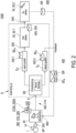
- Part of the software structure 300 of the observer module 20 is also an in Fig. 2 1 shows in more detail fault detection 320 with a fault detection algorithm 320A for detecting a fault relating to the drive device 1.
- Applying the fault detection algorithm 320A to the acquired operating data 200 in the fault detection 320 enables the detection of a fault relating to the operating parameter BP of the drive device 1 based on the specified aspect; this will be in relation to Fig. 2 and then that Fig. 4A and Fig.4B explained in more detail.
- the sending of a fault display 410 is provided, which can indicate a fault in the drive device 1 in relation to an operating parameter BP based on a result E of the fault detection algorithm 320A.
- the fault display 410 can be received directly or via a control by a control entity K in an actuator 30 and, after checking the result E of the fault display 410, for example in a server device, lead to the actuator 30 being activated to the drive device 1 via the control control connection 500.
- the actuating control connection 500 shown here only symbolically, can therefore actuate an actuating path for the direct control and regulation of the drive unit 1 and/or trigger an action that is received as a signal from an external body and carries out the action - in this respect it is in the Fig. 1 the control connection 500 and in this case also the actuator 30 are shown abstractly.
- a feedback loop 600 also symbolically shown here, in the sense of feeding back an operating parameter BP, e.g. B. an ACTUAL value of the same and / or an error ERR to the observer 20 to cause.
- an operating parameter BP e.g. B. an ACTUAL value of the same and / or an error ERR
- Fig. 2 In relation to the aforementioned observer structure of the monitoring method 1000, a concrete example shows a preferred embodiment of an observer structure improved according to the concept of the invention for implementing a data-based monitoring method 1000 according to the concept of the invention.
- the data-based monitoring method 1000 is explained here in relation to a drive device 1 with a control device comprising a controller ECU, a data logger 10, which provides operating parameters BP comprising operating data 200 to an observer module 20.
- the Observer module 20 includes, as part of its modules and data structures 300, observer software 310 or other monitor and fault detection 320.
- a fault display 410 can be automatically fed to a control instance K with a result E of the fault detection algorithm 320A in order to check the result E of the fault display 410, and then, after checking the result E, an actuating control connection 500 and / or a feedback 600 activate.
- the result E of the fault detection algorithm 320A may be an automated message that is transmitted.
- the control entity K is designed in a particularly advantageous manner with a discrimination unit DE, which receives the result E from the observer module 20.
- This discrimination unit DE can, for example, be located in a central office or a central server, or be connected to a suitable other server. In this respect, sufficient computing capacity and data background can be available for this discrimination unit DE and the decision regarding the result E.
- the discrimination unit DE makes a decision based on the appropriate examination of the result E with sufficient computing capacity and data background.
- the result E is checked in the discrimination unit DE and classified according to a criterion or into a category for a false-positive result E F or a true-positive result E P .
- a corresponding qualification signal SE P or SE F is provided, which is also used in different ways in the present case.
- the true-positive signal SE P based on the real - that is, true-positive - result EP namely in this embodiment only the true-positive signal SE P based on the as real qualified true-positive signal SE P-- is made available in a first signaling line 420.1 of the control control connection 500 in order to then provide an actuator 30.
- the false-positive signal SE F based on the artificial -- that is, false-positive -- result E F is made available in a second signaling strand 420.2 of the feedback 600 to the observer module 20; namely in this exemplary embodiment only the false positive signal SE F-
- the actuator 30 has a service and/or verification module 30.1.
- the service and/or verification module 30.1 automatically defines a service or verification action and passes this on as part of the automatic signaling 400 in a first signaling strand 420.1 from the first module as a service and/or verification module 30.1.
- the service or verification action 540 may be influenced by or with a personnel deployment.
- the service or verification action 540 may also, but not only, go to service personnel.
- the service or checking action 540 is passed on in particular as a service signal 430 to an execution module 30.2 of the service unit in the sense of an actuator 30.
- the actuator therefore includes a second module as an execution module 30.2.
- the execution module 30.2 ensures the execution of the service or verification action 540.
- the execution module 30.2 transmits a feedback signal SR after carrying out a defined, possibly predefined service or verification action 540.
- the feedback signal SR is merged as part of the signaling 400 with the previously mentioned false positive signal SE F.
- the feedback signal SR is transmitted as part of the signaling 400 with the aforementioned false positive signal SE F from the second signaling strand 420.2 as part of the feedback 600 to the observer module 20.
- the observer module 20 therefore receives “feedback” not only about the service or checking action 540 carried out, but also about the previously mentioned false positive signal SE F from the second signaling strand 420.2.
- the observer module 600 therefore not only receives the implementation status in the sense of an actual value of the operating parameter BP from the execution module 30.2, but also information about the artificial - i.e. false positive - results E F that are, so to speak, "filtered out" in the discrimination unit DE.
- the monitoring value and the result are sent to the feedback connection to the observer module.
- the observer module 600 is enabled to implement a learning algorithm, which is implemented as an “improved filter” via the discrimination unit DE provided in the control instance for the occurrence of false positive results E F.
- the concept of the invention is implemented in this embodiment in that operating data 200 for operating parameters BP are constantly monitored as a discrete-time sequence and any fault or irregularity is detected. This is done in the discrimination unit DE with a model-based filter model, which enables a plausibility check of the results E, as explained below.
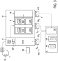
- Fig. 3 shows in a somewhat modified manner - but fundamentally similar - the structure of an observer system for the monitoring method 1000, with reference being made here to the previously mentioned explanations using the same reference numerals.
- the discrimination unit DE of the control entity K is shown here, which is spatially distant from the observer module 20 with or in a computing unit KR designed as a server with memory KS of the control entity K.
- the signaling 400 is therefore primarily carried out wirelessly between the control entity K and the observer module 20
- the signaling is implemented as part of the data logger 10 and the observer module 20, namely as a connection it can be implemented to or in a suitable control device; this can also be with or include the control ECU of the internal combustion engine 1, as symbolically shown in Fig. 3 is shown.
- the true-positive result EP is transmitted as part of a true-positive signaling SE P of the control control connection 500 to an actuator by means of the vehicle control ECU.
- the actuator 30 is designed as an actuator on the vehicle by means of the control ECU in order to control the vehicle with the change in the operating parameters via the actuator 30 in accordance with the true-positive result EP .
- the false positive result E F is made available to the observer module 20 as part of the previously explained false positive signaling SE F , in this case primarily to the observer software or other monitor 310 and/or the fault detection 320, namely for improvement in the framework a learning loop of the monitor algorithm 310A stored there, or fault detection algorithm 320A.
- a model M of the observer module 20, shown symbolically here, is provided, which enables a plausibility check of the results E.
- the plausibility check stipulates that valid basic rules in the sense of functional relationships or correlations are checked between the available operating parameters or the transient, discrete-time sequence of the operating parameters.
- monitoring of the operating parameters BP such as monitoring of the operating and measured variables, can take place. This can be done using an observer system of monitoring method 1000 comprising a physical model M of the drive device with the operating parameters BP for reconstructing states of the drive device taking into account the operating parameters BP.
- the first example of a model filter shown in the model M includes, for example, checking a correlation between the operating parameters BP for an “engine start” and an “oil temperature” T OIL .
- a first exemplary possibility of implementation in relation to one of the aforementioned embodiments of a monitoring method 1000 is explained according to the concept according to the invention in relation to a single drive unit 1, such as an internal combustion engine, with reference to the aforementioned reference numerals using a concrete example of a data record from the data logger 10, the in Fig. 4A are shown in more detail.
- the fault display 410 specifically includes a time-discrete data sequence for operating parameters oil temperature T OIL , boost pressure P L , exhaust gas temperature T AG and idle speed V N for the drive unit 1.
- the monitoring method 1000 therefore provides that the method is used to operate a single drive device 1; and applying the fault detection algorithm includes comparing a current value of an operating parameter with at least a portion of the history of the operating parameter recorded over the operating period.
- the discrimination unit DE can also classify the results of the detections according to a criterion or into a category for a false-positive result E F or a true-positive result E P .
- Fig. 4A it is indicated (symbolically with a tick) how some parameters are recognized or classified as normal or in the nominal range according to the previously explained model filter M. In this case, this applies to the boost pressure P L , the exhaust gas temperature T AG and the idle speeds (nominal speed V N ). However, the operating parameter for the oil temperature T OIL appears to show an anomaly, as shown in the enlarged view for T OIL in Fig. 4A is shown. For these findings or decisions, the discrimination unit DE has sufficient computing capacity and data background due to an appropriate examination of a result E.
- Such an inherently positive result E can be supplied as part of an automated fault display 410 together with the operating state of the internal combustion engine (as the form of a drive unit 1 shown here).
- a discrimination unit DE in the control instance K would here recognize as a result E that the internal combustion engine of the drive unit 1 is obviously in working operation and that there is still a critical gradient development in the oil temperature, albeit still within the limiting threshold ranges Limit LO and Limit HI .
- the discrimination unit DE would therefore characterize this result as true-positive, i.e. real and not artificial.
- a corresponding true-positive signal SE P can, for example, contain the message that the internal combustion engine has a critical gradient in the oil temperature T OIL .
- the data packet shown in DE can be included around the time of operation. Instructions may be included to check the operating status of the internal combustion engine.
- a result E which includes a noticeable increase in oil temperature, would therefore NOT lead to the forwarding of a fault display 410 for the first signaling line 420.1, in the event of an engine start - rather, in the sense of a signaling 400, it would be fed to a second signaling line 420.2 for feedback 600.
- the detection of an artificial - i.e. false positive - result E F can, for example, include a combination of information regarding the location of the drive unit 1 (e.g. available via GPS) and the operating parameter BP is.
- the information may be available that the drive unit 1 is not running and the information that a slight increase in the oil pressure between the states of an “engine stop” and “engine start” can be reported. This could signal an oil filter change.
- a corresponding fault display 410 for the first signaling line 420.1 can be triggered via the actuator 30 to trigger a filter change action.
- the process can improve the monitoring and interference detection algorithms 310A, 320A in the sense of algorithm training.
- a corresponding training algorithm T310, T320 may be provided to increase the detection rate for false positive results and thus reduce the number of false positive results.
- the model filter module can issue recommendations and also cause the actuator 30 to take actions.
- such a model filter can be implemented in the controller or the observer module 20, since it can be implemented with comparatively little computing effort.
- more complex tests of the results E for artificial or genuine are arranged as part of the discrimination unit DE in the control instance K.
- a discrimination unit can also be part of the observer module 20 and be arranged following a model filter M or directly after the filter module F (comprising the monitor and interference detection algorithm 310A, 320A).
- a third example may concern the combination of operating parameters BP for a situation explained below: An inlet pressure has a noticeable pressure loss, while there is a constant pressure in front of the turbocharger and a constant inlet air temperature.
- a corresponding fault display 410 can be made for the first signaling line 420.1 and it can be recognized in the service and/or checking module 30.1 that there is a 70% probability that there is a turbocharger problem.
- the actuator 30 in the sense of an actuator of the actuating unit can therefore, depending on the operating situation of the drive unit 1, provide a throttle position for the inlet air at the inlet manifold in order to maintain the inlet pressure or to be able to operate the turbocharger at higher speeds.
- the execution module 30.2 can issue a recommendation to check the turbocharger.
- Such and other operating parameters BP than those previously mentioned as examples can be recorded as a discrete-time operating data sequence, the disturbance being recognized as a disturbance curve of an operating parameter BP for the discrete-time operating data sequence; for example by means of a threshold value analysis of the operating data for an operating parameter BP.
- a technical fault area of the drive device can also be assigned to the fault and/or displayed, the fault display comprising the fault progression and fault area.
- each fault identification criterion can be assigned fault origin information that contains information about the origin of the fault; and that Fault indication signal indicates the fault origin information that is assigned to the fault identification criterion, based on the result of which the fault indication signal was sent.
- Fig. 4B is another fourth example of a model filter in the model M explained.
- Fig. 4B shows a further exemplary possible implementation in relation to one of the aforementioned advantageous embodiments of a monitoring method 1000; presently in relation to a fleet with a plurality of drive units.
- Fig. 4B again shows the processes in a discrimination unit DE of a control instance K in relation to a fleet of a plurality of drive units 1.
- a result E is transmitted as a fault display 410, in which a correlation of the same is plotted with respect to a first specific operating parameter value BP1 and a second specific operating parameter value BP2; namely 1 N for each of the drive units.
- the corresponding operating parameters BP are referred to here as BP n .
- the operating parameter BP x for the drive unit Ie the method for operating a plurality of drive units N is used and at least one operating parameter BP n is recorded for each of the drive units N.
- Applying the fault detection algorithm includes comparing a value of an operating parameter BP x of a drive device X with values of the operating parameter BP n of the remaining of the plurality of drive devices N.
- a distance A to the average D of the ensemble of operating parameters BP n can be defined with respect to each of the operating parameters BP n .
- a true positive result is output here as part of a true positive signaling SE P with corresponding signaling 420.1 from a service and/or verification module 30.1 to an execution module 30.2.
- This procedure can - in addition to using the in Fig. 4B shown distance in relation to a threshold value - a number of other statistical evaluation methods for specifying a result E.
- the distance can be --as in Fig. 4B shown-- with an essentially fixed distance dimension A. Additionally or alternatively, the distance --as in Fig. 4B is shown-- can also be given with a distance measure A(t) as a function of time. An aforementioned distance measure A, A(t) can be used to determine the distance. In addition, it can also be used to group error situations in a statistical manner, which can be defined more generally and/or independently of the type of a specific operating parameter BP n . can be determined.
Landscapes
- Engineering & Computer Science (AREA)
- Physics & Mathematics (AREA)
- General Physics & Mathematics (AREA)
- Automation & Control Theory (AREA)
- Chemical & Material Sciences (AREA)
- Combustion & Propulsion (AREA)
- Mechanical Engineering (AREA)
- General Engineering & Computer Science (AREA)
- Testing And Monitoring For Control Systems (AREA)
- Combined Controls Of Internal Combustion Engines (AREA)
Applications Claiming Priority (1)
| Application Number | Priority Date | Filing Date | Title |
|---|---|---|---|
| DE102022121716.7A DE102022121716B3 (de) | 2022-08-26 | 2022-08-26 | Überwachungsverfahren für den Betrieb einer Anzahl von einer oder mehreren Antriebseinrichtungen, insbesondere für den Betrieb einer Brennkraftmaschine, und System ausgebildet für das Überwachungsverfahren |
Publications (3)
| Publication Number | Publication Date |
|---|---|
| EP4328693A1 true EP4328693A1 (fr) | 2024-02-28 |
| EP4328693C0 EP4328693C0 (fr) | 2025-07-09 |
| EP4328693B1 EP4328693B1 (fr) | 2025-07-09 |
Family
ID=87845678
Family Applications (1)
| Application Number | Title | Priority Date | Filing Date |
|---|---|---|---|
| EP23193510.7A Active EP4328693B1 (fr) | 2022-08-26 | 2023-08-25 | Procédé de surveillance du fonctionnement d'un certain nombre de dispositifs d'entrainement , en particulier pour le fonctionnement d'un moteur à combustion interne, et système conçu pour le procédé de surveillance |
Country Status (3)
| Country | Link |
|---|---|
| EP (1) | EP4328693B1 (fr) |
| DE (1) | DE102022121716B3 (fr) |
| ES (1) | ES3042365T3 (fr) |
Citations (6)
| Publication number | Priority date | Publication date | Assignee | Title |
|---|---|---|---|---|
| WO2018007802A1 (fr) | 2016-07-04 | 2018-01-11 | Centrica Connected Home Limited | Détermination de débit |
| US20180148037A1 (en) | 2016-11-30 | 2018-05-31 | Ford Global Technologies, Llc | Identifying in-range fuel pressure sensor error |
| US20180158314A1 (en) * | 2016-12-02 | 2018-06-07 | Aktiebolaget Skf | Method of trend analysis and automatic tuning of alarm parameters |
| WO2019106534A1 (fr) | 2017-12-01 | 2019-06-06 | 3M Innovative Properties Company | Analyse causale pour gestion de groupe motopropulseur |
| US20190310618A1 (en) | 2018-04-06 | 2019-10-10 | Hitachi, Ltd. | System and software for unifying model-based and data-driven fault detection and isolation |
| US20190353131A1 (en) | 2018-05-21 | 2019-11-21 | Ford Global Technologies, Llc | Method and system for variable displacement engine knock control |
-
2022
- 2022-08-26 DE DE102022121716.7A patent/DE102022121716B3/de active Active
-
2023
- 2023-08-25 EP EP23193510.7A patent/EP4328693B1/fr active Active
- 2023-08-25 ES ES23193510T patent/ES3042365T3/es active Active
Patent Citations (6)
| Publication number | Priority date | Publication date | Assignee | Title |
|---|---|---|---|---|
| WO2018007802A1 (fr) | 2016-07-04 | 2018-01-11 | Centrica Connected Home Limited | Détermination de débit |
| US20180148037A1 (en) | 2016-11-30 | 2018-05-31 | Ford Global Technologies, Llc | Identifying in-range fuel pressure sensor error |
| US20180158314A1 (en) * | 2016-12-02 | 2018-06-07 | Aktiebolaget Skf | Method of trend analysis and automatic tuning of alarm parameters |
| WO2019106534A1 (fr) | 2017-12-01 | 2019-06-06 | 3M Innovative Properties Company | Analyse causale pour gestion de groupe motopropulseur |
| US20190310618A1 (en) | 2018-04-06 | 2019-10-10 | Hitachi, Ltd. | System and software for unifying model-based and data-driven fault detection and isolation |
| US20190353131A1 (en) | 2018-05-21 | 2019-11-21 | Ford Global Technologies, Llc | Method and system for variable displacement engine knock control |
Also Published As
| Publication number | Publication date |
|---|---|
| EP4328693C0 (fr) | 2025-07-09 |
| ES3042365T3 (en) | 2025-11-20 |
| DE102022121716B3 (de) | 2023-11-02 |
| EP4328693B1 (fr) | 2025-07-09 |
Similar Documents
| Publication | Publication Date | Title |
|---|---|---|
| DE10017788B4 (de) | Fehlererkennungssystem und -verfahren für einen Verbrennungsmotor | |
| DE102019219332A1 (de) | Lerndatenprüfung-Unterstütztungsvorrichtung, Maschinelles-Lernen-Vorrichtung und Ausfallvorhersagevorrichtung | |
| EP1892597A1 (fr) | Surveillance de machines et d'installations techniques | |
| EP0789864B1 (fr) | Systeme de controle pour installation industrielle | |
| DE112015004142T5 (de) | System und Verfahren zur Vorhersage des Ausfalls von Maschinenkomponenten | |
| DE10007308A1 (de) | Verfahren und Vorrichtung zur Ermittlung der verbleibenden Betriebsdauer eines Produktes | |
| DE102015210210A1 (de) | Verfahren zur Diagnose eines Membranventils, sowie Diagnosesystem für ein Membranventil | |
| EP3882828B1 (fr) | Procédé de surveillance d'un réseau d'alimentation en eau, réseau d'alimentation en eau et système de détection des défauts | |
| DE102020108861A1 (de) | Verfahren zum Ermitteln eines Zustands eines Bauteils | |
| EP3033513A1 (fr) | Procédé permettant le diagnostic pour chaque injecteur d'un dispositif d'injection de carburant et moteur à combustion interne pourvu d'un dispositif d'injection de carburant | |
| EP3640477B1 (fr) | Développement d'un modèle parent pour commander et/ou surveiller une installation de compresseur | |
| DE102021203806A1 (de) | Verfahren zur Überwachung des Betriebs eines Ventilators, Vorrichtung und Ventilator | |
| DE112019001471T5 (de) | Vorrrichtung zur Fehlerdiagnose und Verfahren zur Fehlerdiagnose | |
| DE102022121716B3 (de) | Überwachungsverfahren für den Betrieb einer Anzahl von einer oder mehreren Antriebseinrichtungen, insbesondere für den Betrieb einer Brennkraftmaschine, und System ausgebildet für das Überwachungsverfahren | |
| EP2971769B1 (fr) | Entrée de schéma r&i pour un procédé de contrôle et/ou de surveillance d'un système de compresseurs | |
| DE102023207829B4 (de) | Verfahren und System zum Erkennen von Anomalien in einem Satz von Signalen | |
| EP3929554A1 (fr) | Détection améliorée d'erreurs dans les machines au moyen de l'ia | |
| DE102024207730A1 (de) | Verfahren zur erstellung eines vorhersagemodells sowie verfahren und vorrichtung zur detektion von ansaugluftleckagen | |
| WO2024133521A1 (fr) | Procédé, dispositif de diagnostic et système de surveillance du fonctionnement d'un moteur à combustion interne | |
| DE10302054B4 (de) | Verfahren zum Betreiben einer Brennkraftmaschine | |
| DE102019107242A1 (de) | Diagnoseverfahren, Diagnosesystem und Kraftfahrzeug | |
| DE102019107240A1 (de) | Diagnoseverfahren, Diagnosesystem und Kraftfahrzeug | |
| DE102020121890A1 (de) | Verfahren zur Diagnose eines Steuer- und/oder Regelungssystems sowie Steuer- und/oder Regelungssystem | |
| DE102019122727A1 (de) | Verfahren und Einrichtung zur Überwachung einer Antriebseinheit mit einer drehenden Antriebskomponente, insbesondere eines Motors einer Brennkraftmaschine mit einer Kurbelwelle, sowie Anzahl von Antriebseinheiten mit der Einrichtung | |
| DE19916994C1 (de) | Verfahren zur Überwachung einer Brennkraftmaschine |
Legal Events
| Date | Code | Title | Description |
|---|---|---|---|
| PUAI | Public reference made under article 153(3) epc to a published international application that has entered the european phase |
Free format text: ORIGINAL CODE: 0009012 |
|
| STAA | Information on the status of an ep patent application or granted ep patent |
Free format text: STATUS: THE APPLICATION HAS BEEN PUBLISHED |
|
| AK | Designated contracting states |
Kind code of ref document: A1 Designated state(s): AL AT BE BG CH CY CZ DE DK EE ES FI FR GB GR HR HU IE IS IT LI LT LU LV MC ME MK MT NL NO PL PT RO RS SE SI SK SM TR |
|
| STAA | Information on the status of an ep patent application or granted ep patent |
Free format text: STATUS: REQUEST FOR EXAMINATION WAS MADE |
|
| 17P | Request for examination filed |
Effective date: 20240828 |
|
| RBV | Designated contracting states (corrected) |
Designated state(s): AL AT BE BG CH CY CZ DE DK EE ES FI FR GB GR HR HU IE IS IT LI LT LU LV MC ME MK MT NL NO PL PT RO RS SE SI SK SM TR |
|
| GRAP | Despatch of communication of intention to grant a patent |
Free format text: ORIGINAL CODE: EPIDOSNIGR1 |
|
| STAA | Information on the status of an ep patent application or granted ep patent |
Free format text: STATUS: GRANT OF PATENT IS INTENDED |
|
| INTG | Intention to grant announced |
Effective date: 20250130 |
|
| GRAS | Grant fee paid |
Free format text: ORIGINAL CODE: EPIDOSNIGR3 |
|
| GRAA | (expected) grant |
Free format text: ORIGINAL CODE: 0009210 |
|
| STAA | Information on the status of an ep patent application or granted ep patent |
Free format text: STATUS: THE PATENT HAS BEEN GRANTED |
|
| AK | Designated contracting states |
Kind code of ref document: B1 Designated state(s): AL AT BE BG CH CY CZ DE DK EE ES FI FR GB GR HR HU IE IS IT LI LT LU LV MC ME MK MT NL NO PL PT RO RS SE SI SK SM TR |
|
| REG | Reference to a national code |
Ref country code: GB Ref legal event code: FG4D Free format text: NOT ENGLISH |
|
| REG | Reference to a national code |
Ref country code: CH Ref legal event code: EP |
|
| REG | Reference to a national code |
Ref country code: IE Ref legal event code: FG4D Free format text: LANGUAGE OF EP DOCUMENT: GERMAN |
|
| REG | Reference to a national code |
Ref country code: DE Ref legal event code: R096 Ref document number: 502023001309 Country of ref document: DE |
|
| U01 | Request for unitary effect filed |
Effective date: 20250807 |
|
| U07 | Unitary effect registered |
Designated state(s): AT BE BG DE DK EE FI FR IT LT LU LV MT NL PT RO SE SI Effective date: 20250819 |
|
| PGFP | Annual fee paid to national office [announced via postgrant information from national office to epo] |
Ref country code: ES Payment date: 20250926 Year of fee payment: 3 |
|
| U20 | Renewal fee for the european patent with unitary effect paid |
Year of fee payment: 3 Effective date: 20250924 |
|
| REG | Reference to a national code |
Ref country code: ES Ref legal event code: FG2A Ref document number: 3042365 Country of ref document: ES Kind code of ref document: T3 Effective date: 20251120 |
|
| PG25 | Lapsed in a contracting state [announced via postgrant information from national office to epo] |
Ref country code: IS Free format text: LAPSE BECAUSE OF FAILURE TO SUBMIT A TRANSLATION OF THE DESCRIPTION OR TO PAY THE FEE WITHIN THE PRESCRIBED TIME-LIMIT Effective date: 20251109 |
|
| PG25 | Lapsed in a contracting state [announced via postgrant information from national office to epo] |
Ref country code: NO Free format text: LAPSE BECAUSE OF FAILURE TO SUBMIT A TRANSLATION OF THE DESCRIPTION OR TO PAY THE FEE WITHIN THE PRESCRIBED TIME-LIMIT Effective date: 20251009 |
|
| PG25 | Lapsed in a contracting state [announced via postgrant information from national office to epo] |
Ref country code: HR Free format text: LAPSE BECAUSE OF FAILURE TO SUBMIT A TRANSLATION OF THE DESCRIPTION OR TO PAY THE FEE WITHIN THE PRESCRIBED TIME-LIMIT Effective date: 20250709 |
|
| PG25 | Lapsed in a contracting state [announced via postgrant information from national office to epo] |
Ref country code: GR Free format text: LAPSE BECAUSE OF FAILURE TO SUBMIT A TRANSLATION OF THE DESCRIPTION OR TO PAY THE FEE WITHIN THE PRESCRIBED TIME-LIMIT Effective date: 20251010 |
|
| PG25 | Lapsed in a contracting state [announced via postgrant information from national office to epo] |
Ref country code: PL Free format text: LAPSE BECAUSE OF FAILURE TO SUBMIT A TRANSLATION OF THE DESCRIPTION OR TO PAY THE FEE WITHIN THE PRESCRIBED TIME-LIMIT Effective date: 20250709 |
|
| PG25 | Lapsed in a contracting state [announced via postgrant information from national office to epo] |
Ref country code: RS Free format text: LAPSE BECAUSE OF FAILURE TO SUBMIT A TRANSLATION OF THE DESCRIPTION OR TO PAY THE FEE WITHIN THE PRESCRIBED TIME-LIMIT Effective date: 20251009 |
|
| PG25 | Lapsed in a contracting state [announced via postgrant information from national office to epo] |
Ref country code: SM Free format text: LAPSE BECAUSE OF FAILURE TO SUBMIT A TRANSLATION OF THE DESCRIPTION OR TO PAY THE FEE WITHIN THE PRESCRIBED TIME-LIMIT Effective date: 20250709 |
|
| PG25 | Lapsed in a contracting state [announced via postgrant information from national office to epo] |
Ref country code: CZ Free format text: LAPSE BECAUSE OF FAILURE TO SUBMIT A TRANSLATION OF THE DESCRIPTION OR TO PAY THE FEE WITHIN THE PRESCRIBED TIME-LIMIT Effective date: 20250709 |
|
| PG25 | Lapsed in a contracting state [announced via postgrant information from national office to epo] |
Ref country code: SK Free format text: LAPSE BECAUSE OF FAILURE TO SUBMIT A TRANSLATION OF THE DESCRIPTION OR TO PAY THE FEE WITHIN THE PRESCRIBED TIME-LIMIT Effective date: 20250709 |