EP4328954A1 - Zweifrequenz-ionenfallen-avr-abtastung für verbesserte leistung im hochmassenbereich - Google Patents
Zweifrequenz-ionenfallen-avr-abtastung für verbesserte leistung im hochmassenbereich Download PDFInfo
- Publication number
- EP4328954A1 EP4328954A1 EP23193396.1A EP23193396A EP4328954A1 EP 4328954 A1 EP4328954 A1 EP 4328954A1 EP 23193396 A EP23193396 A EP 23193396A EP 4328954 A1 EP4328954 A1 EP 4328954A1
- Authority
- EP
- European Patent Office
- Prior art keywords
- ion trap
- ions
- value
- ion
- scan
- Prior art date
- Legal status (The legal status is an assumption and is not a legal conclusion. Google has not performed a legal analysis and makes no representation as to the accuracy of the status listed.)
- Pending
Links
- 238000005040 ion trap Methods 0.000 title claims abstract description 234
- 238000004458 analytical method Methods 0.000 claims abstract description 12
- 150000002500 ions Chemical class 0.000 claims description 206
- 238000002347 injection Methods 0.000 claims description 17
- 239000007924 injection Substances 0.000 claims description 17
- 238000004949 mass spectrometry Methods 0.000 claims description 15
- 230000015654 memory Effects 0.000 claims description 15
- 238000002474 experimental method Methods 0.000 claims description 11
- 230000003247 decreasing effect Effects 0.000 claims description 8
- 238000000034 method Methods 0.000 abstract description 136
- 238000013459 approach Methods 0.000 abstract description 5
- 238000005516 engineering process Methods 0.000 abstract description 4
- 238000001514 detection method Methods 0.000 description 11
- 230000008569 process Effects 0.000 description 7
- 238000012545 processing Methods 0.000 description 7
- 238000004891 communication Methods 0.000 description 6
- 238000012546 transfer Methods 0.000 description 6
- 230000006870 function Effects 0.000 description 5
- 238000009795 derivation Methods 0.000 description 4
- 238000010494 dissociation reaction Methods 0.000 description 4
- 230000005593 dissociations Effects 0.000 description 4
- 230000005672 electromagnetic field Effects 0.000 description 4
- 230000005405 multipole Effects 0.000 description 4
- 230000003287 optical effect Effects 0.000 description 4
- 230000005540 biological transmission Effects 0.000 description 3
- 238000006243 chemical reaction Methods 0.000 description 3
- 239000003153 chemical reaction reagent Substances 0.000 description 3
- 230000005284 excitation Effects 0.000 description 3
- 239000002243 precursor Substances 0.000 description 3
- 238000009825 accumulation Methods 0.000 description 2
- 230000000694 effects Effects 0.000 description 2
- 238000001077 electron transfer detection Methods 0.000 description 2
- 238000013467 fragmentation Methods 0.000 description 2
- 238000006062 fragmentation reaction Methods 0.000 description 2
- 230000007935 neutral effect Effects 0.000 description 2
- 230000037361 pathway Effects 0.000 description 2
- 238000012805 post-processing Methods 0.000 description 2
- 238000006276 transfer reaction Methods 0.000 description 2
- 230000004913 activation Effects 0.000 description 1
- 238000001360 collision-induced dissociation Methods 0.000 description 1
- 239000000356 contaminant Substances 0.000 description 1
- 238000001816 cooling Methods 0.000 description 1
- 238000010586 diagram Methods 0.000 description 1
- 230000007613 environmental effect Effects 0.000 description 1
- 238000010884 ion-beam technique Methods 0.000 description 1
- -1 ions ion Chemical class 0.000 description 1
- 239000007788 liquid Substances 0.000 description 1
- 238000012423 maintenance Methods 0.000 description 1
- 230000014759 maintenance of location Effects 0.000 description 1
- 238000007726 management method Methods 0.000 description 1
- 238000005259 measurement Methods 0.000 description 1
- 230000007246 mechanism Effects 0.000 description 1
- 230000008520 organization Effects 0.000 description 1
- 238000006303 photolysis reaction Methods 0.000 description 1
- 229920001690 polydopamine Polymers 0.000 description 1
- 238000005086 pumping Methods 0.000 description 1
- 230000009467 reduction Effects 0.000 description 1
- 238000000926 separation method Methods 0.000 description 1
- 238000001228 spectrum Methods 0.000 description 1
- 230000004304 visual acuity Effects 0.000 description 1
Images


Classifications
-
- H—ELECTRICITY
- H01—ELECTRIC ELEMENTS
- H01J—ELECTRIC DISCHARGE TUBES OR DISCHARGE LAMPS
- H01J49/00—Particle spectrometers or separator tubes
- H01J49/26—Mass spectrometers or separator tubes
- H01J49/34—Dynamic spectrometers
- H01J49/42—Stability-of-path spectrometers, e.g. monopole, quadrupole, multipole, farvitrons
- H01J49/426—Methods for controlling ions
- H01J49/427—Ejection and selection methods
- H01J49/429—Scanning an electric parameter, e.g. voltage amplitude or frequency
-
- H—ELECTRICITY
- H01—ELECTRIC ELEMENTS
- H01J—ELECTRIC DISCHARGE TUBES OR DISCHARGE LAMPS
- H01J49/00—Particle spectrometers or separator tubes
- H01J49/0027—Methods for using particle spectrometers
- H01J49/0031—Step by step routines describing the use of the apparatus
-
- H—ELECTRICITY
- H01—ELECTRIC ELEMENTS
- H01J—ELECTRIC DISCHARGE TUBES OR DISCHARGE LAMPS
- H01J49/00—Particle spectrometers or separator tubes
- H01J49/02—Details
- H01J49/025—Detectors specially adapted to particle spectrometers
-
- H—ELECTRICITY
- H01—ELECTRIC ELEMENTS
- H01J—ELECTRIC DISCHARGE TUBES OR DISCHARGE LAMPS
- H01J49/00—Particle spectrometers or separator tubes
- H01J49/26—Mass spectrometers or separator tubes
- H01J49/34—Dynamic spectrometers
- H01J49/42—Stability-of-path spectrometers, e.g. monopole, quadrupole, multipole, farvitrons
- H01J49/4205—Device types
- H01J49/422—Two-dimensional RF ion traps
- H01J49/4225—Multipole linear ion traps, e.g. quadrupoles, hexapoles
-
- H—ELECTRICITY
- H01—ELECTRIC ELEMENTS
- H01J—ELECTRIC DISCHARGE TUBES OR DISCHARGE LAMPS
- H01J49/00—Particle spectrometers or separator tubes
- H01J49/26—Mass spectrometers or separator tubes
- H01J49/34—Dynamic spectrometers
- H01J49/42—Stability-of-path spectrometers, e.g. monopole, quadrupole, multipole, farvitrons
- H01J49/426—Methods for controlling ions
- H01J49/4265—Controlling the number of trapped ions; preventing space charge effects
-
- H—ELECTRICITY
- H01—ELECTRIC ELEMENTS
- H01J—ELECTRIC DISCHARGE TUBES OR DISCHARGE LAMPS
- H01J49/00—Particle spectrometers or separator tubes
- H01J49/26—Mass spectrometers or separator tubes
- H01J49/34—Dynamic spectrometers
- H01J49/42—Stability-of-path spectrometers, e.g. monopole, quadrupole, multipole, farvitrons
- H01J49/426—Methods for controlling ions
- H01J49/427—Ejection and selection methods
Definitions
- FIGS. 1A and 1B are relative intensity graphs of mass spectrometry analysis of an Ultramark ® Mass Spec standard that were obtained using a first continuous scan across a Thompson value range of 1000-10000 Thompson value ( FIG. 1A ) and a second continuous scan across a Thompson value range of 2000-10000 Thompson value (FIG. 2A).
- graph 100 shows a reduced detection rate of ion species 104 within the 4000-7000 Thompson value range and an absence of any ions detected within the 7000-10000 Thompson value range.
- FIG. 1B shows a graph 150 of a mass spectrometry analysis of the same standard but with a higher bottom Thompson value range of the continuous scan.
- this second scan has an increased detection rate of ion species 152 within the 4000-7000 Thompson value range and includes the data for ions species 154 within the 7000-10000 Thompson value range that were completely lost in the first scan.
- mass spectrometry systems be capable of analyzing or otherwise handling samples having wider ranges of Thompson value values without losing resolution or suffering from discrimination of high Thompson value ion species.
- This system and method disclosed herein are configured to improve high mass range ion trap performance by use of a multi-directional segmented scan approach.
- the mass range of conventional ion trap technology may be extended/increased without changing the hardware or compromising lower range mass/charge efficiency.
- the system and methods disclosed herein use a segmented, bi-directional scan that increases the mass range of an ion trap mass spectrometer and circumvents the problem of mass discrimination during mass analysis in the high Thompson value range.
- FIG. 2 shows an example embodiment of a method 200 according to the present disclosure.
- a plurality of ions are generated and injected into an ion trap.
- Initial ejection parameters of the ion trap are optionally set, and then ion trap is caused to perform a first scan out of ions by systematically increasing the main RF voltage applied to the ion trap from a first RF value to a second RF value.
- new ejection parameters of the ion trap are optionally set, and then ion trap is caused to perform a second scan out of ions by systematically decreasing the main RF voltage applied to the ion trap from a third RF value to a fourth RF value.
- the method 200 is able to obtain mass spectrometry analysis for ion populations containing ion species having wide range of Thompson values with reduced discrimination against high Thompson value species.
- weight may further be applied to the detector data for each scan to account for the expected ejection efficiency for each scan.
- FIG. 3 shows an example process 300 where the system and method of the present disclosure is incorporated into a pre-scan procedure.
- Ion traps operate optimally when they contain a particular quantity of ion charge, with different ion traps being designed to optimally handle different quantities of ions.
- the rate delivery to and injection into an ion trap may vary over a large range because sample abundance may vary strongly with time such as when the sample delivery system is a liquid chromatograph.
- AGC Automatic Gain Control
- On widely used approach of performing AGC is to perform a "pre scan” experiment to determine the rate of ion accumulation in ion trap when ions are gated in and follow up with a second "analytical scan” experiment wherein the ion injection time is determined based on an estimation of the ion accumulation rate determined from the pre scan experiment so as to have a near optimal population of the ion trap.
- the results from that experiment are the ones generally recorded as analytical data.
- FIG. 3 shows an example method where the segmented, bi-directional scan process shown in FIG. 2 is incorporated as a pre-scan experiment.
- the quantity of ions determined in the method of FIG. 2 can be used to determine the injection rate of ions into the ion trap (e.g., by dividing the determined quantity of ion charge by the amount of time that ions were allowed to pass into the ion trap). This injection rate of ions can then be used to determine the amount of time that ions should be allowed to flow into the ion trap (the same ion trap or a different ion trap) to ensure that the optimal quantity of ions are within the ion trap.
- steps that are optional are shown having dashed outlines.
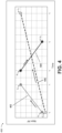
- FIG. 4 shows a graphical representation 400 of the segmented, bi-directional scan process of the present disclosure.
- graph 400 shows a first scan segment 402 in which the main RF voltage is increased from A 0 to A n during the time period t 0 -t 1 , and a second scan segment 404 in which the main RF voltage is decreased from B0 to Bn during the time period t 2 -t 3 .
- the species of ions that are ejected during the two concatenated scans can be different.
- increasing the main RF from A 0 to A n may cause the m/z sequential ejection of ion species starting at a m/z of 1000 Th (Th, Thompson is a proposed unit of for m/z - Daltons/number of elementary charges) and up to m/z 2000 Th to be ejected from the ion trap.
- increasing the main RF voltage from A 0 to A n may correspond to increasing the main RF voltage on the system so that it is equal to or close to the maximum magnitude of main RF voltage that is permitted to apply.
- decreasing the main RF voltage from B 0 to B n may cause the m/z sequential ejection of trapped ion species starting from a m/z of 16000 Th down to 2000 Thompsons.
- decreasing the main RF from B 0 to B n may correspond to decreasing the main RF voltage on the system from close to the maximum magnitude of main RF voltage the ion trap can handle to a lower RF value.
- Graph 400 also shows the prior art process 406 where, RF voltage would be ramped while using the auxiliary AC frequency of the second scan from C 0 to C n over time period t 0 -t 4 , which theoretically should scan out ions m/z sequentially from a m/z of 1000 Th to a m/z of 16,000 Th.
- this results in a high discrimination against the retention and thus detection of high m/z ion species because the initial main RF Voltage, C 0 , is too low to effect radial confinement of the high m/z ions with near thermal kinetic energies.
- FIG. 5 illustrates an example system 500 comprising an ion trap 502 composed of parallel sets of electrodes 502(a) and 502(b).
- linear ion traps may include a slit 504 that allows ions 506 to be ejected from the ion trap when they achieve resonance.
- FIG. 5 further shows how the ejected ions may be detected by a detector system 510 when they are incident on a detection surface 508.
- FIG. 6 shows an environment 600 for practicing the systems and methods of the present disclosure.
- Environment 600 shows a mass spectrometer 602 comprising an ion source 604, and ion trap 606, a detector system 608, and an optional additional ion trap 610.
- FIG. 6 further shows computing devices 612 as being separate from the mass spectrometer 602. However, a person having skill in the art would understand the computing devices 612 may be incorporated in whole or in part into the mass spectrometer 602.
- FIG. 7 illustrates example environments 700 for improving high mass range ion trap performance by use of a multi-directional segmented scan approach.
- FIG. 7 shows an example environment 702 that includes an example mass spectrometer system 704 for complex mass spectrometry experiments and measurements using low Mathieu q dissociation of precursor ions, and computing devices 706 configured to control the operation of the mass spectrometer system 704 and/or perform post processing on detector data generated therefrom.
- present disclosure is not limited to environments that include mass spectrometers, and that in some embodiments the environments 700 may include a different type of system that is configured to manipulate and/or otherwise examine ions within an ion trap, or may only include the computing devices 706.
- the example mass spectrometer system 704 may be or include one or more different types of mass spectrometers known in the art that comprise an ion trap 708 configured to allow for the dissociation of precursor ions (e.g., RF quadrupole ion trap devices, etc.).
- precursor ions e.g., RF quadrupole ion trap devices, etc.
- FIG. 7 shows the example microscope system(s) 704 as being a hybrid mass spectrometer 710, comprising more than one type of mass analyzer.
- the mass spectrometer system 710 includes a quadrupole ion trap mass analyzer 708 as well as an electrostatic trap mass analyzer 712 (e.g., ORBITRAP TM analyzer).
- electrostatic trap mass analyzer 712 e.g., ORBITRAP TM analyzer.
- example microscope systems 704 may include a fewer or greater number of mass analyzers and/or comprise different combinations of mass analyzers.
- an electrospray ion source 714 provides ions of a sample to be analyzed to an aperture of a heated ion transfer tube 716, at which point the ions enter into a first vacuum chamber 718. After entry, the ions are captured and focused into a tight beam by an ion collimating device 720 (e.g., a stacked-ring ion guide, an ion lens, an ion funnel, etc.).
- the example spectrometer 710 is further shows as including a plurality of ion optical transfer components 722 that are configured to allow ions to pass between intermediate-vacuum regions of the mass spectrometer during travel.
- Example spectrometer 710 is illustrated as including a curved beam guide 724 that separates most remaining neutral molecules and undesirable ion clusters (e.g., solvated ions, environmental contaminants, etc.) from the ion beam. For example, neutral molecules and ion clusters follow a straight-line path whereas the paths of ions of interest are bent around the ninety-degree turn of the curved beam guide 724, thereby producing the separation.
- neutral molecules and ion clusters follow a straight-line path whereas the paths of ions of interest are bent around the ninety-degree turn of the curved beam guide 724, thereby producing the separation.
- a quadrupole mass filter 726 of the mass spectrometer system 710 is used in its conventional sense as a tunable mass filter so as to pass ions only within a selected m / z range.
- a subsequent ion optical transfer component 722 delivers the filtered ions to a curved ion trap (“C-trap") component 728.
- the C-trap 728 is able to transfer ions along a pathway between the quadrupole mass filter 726 and the ion trap mass analyzer 708.
- the C-trap 728 also has the capability to temporarily collect and store a population of ions and then deliver the ions, as a pulse or packet, into the mass analyzer 712.
- FIG. 7 further shows a multipole ion guide 730 and an optical transfer component 722 as serving to guide ions between the C-trap 728 and the ion trap mass analyzer 708.
- the multipole ion guide 730 may provide temporary ion storage capability such that ions produced in a first processing step of an analysis method can be later retrieved for processing in a subsequent step.
- the multipole ion guide 730 may also serve as a fragmentation cell and ion trap (i.e., an ion routing multipole).
- Various ion optics along the pathway between the C-trap 728 and the ion trap mass analyzer 708 may be controllable such that ions may be transferred in either direction, depending upon the sequence of ion processing steps required in a particular analysis method.
- the ion trap mass analyzer 708 is illustrated in FIG. 7 as being a dual-pressure linear ion trap 732 (i.e., a two-dimensional trap) comprising a high-pressure linear trap cell 734 and a low-pressure linear trap cell 736, the two cells being positioned adjacent to one another and separated by a plate lens having a small aperture that permits ion transfer between the two cells and that also acts as a pumping restriction that allows different pressures to be maintained in the two traps.
- a person having skill in the art would understand that other types of ion traps 708 are capable of performing the multi-directional segmented scan approach disclosed herein, and thus may be used according to the present disclosure.
- the environment of the high-pressure cell 734 favors ion trapping, ion cooling, ion fragmentation by either collision-induced dissociation or pulsed-q dissociation, ion/ion reactions by either electron transfer dissociation or proton-transfer reactions, and some types of photon activation, such as ultraviolet photo dissociation (UVPD).
- the environment of the low-pressure cell 736 favors analytical scanning with high resolving power and mass accuracy.
- the ion trap 708 further is shown as including an ion detector 738 (e.g., a dual-dynode ion detector).
- the example mass spectrometer system 110 is depicted as including a reagent-ion source 740 disposed between the stacked-ring ion guide 120 and the curved beam guide 724. However, within the present disclosure one or more additional reagent-ion sources may be included in an example mass spectrometer system 704.
- FIG. 7 further illustrates the example spectrometer 710 as including one or more additional components 742.
- example spectrometer 710 is merely an example configuration of a system capable of enabling/performing the system and methods for low Mathieu q dissociation of precursor ions disclosed herein.
- the environment 700 is also shown as including one or more computing device(s) 706.
- computing devices 706 depicted in FIG. 7 are merely illustrative and are not intended to limit the scope of the present disclosure.
- the computing system and devices may include any combination of hardware or software that can perform the indicated functions, including computers, network devices, internet appliances, PDAs, wireless phones, controllers, oscilloscopes, amplifiers, etc.
- the computing devices 706 may also be connected to other devices that are not illustrated, or instead may operate as a stand-alone system.
- one or more of the computing device(s) 706 may be a component of the example mass spectrometers 704, may be a separate device from the example mass spectrometers 704 which is in communication with the example mass spectrometers 704 via a network communication interface, or a combination thereof.
- an example mass spectrometers 704 may include a first computing device 706 that is a component portion of the example mass spectrometers 704, and which acts as a controller that drives the operation of the example mass spectrometers 704 (e.g., adjust the scanning location on the sample by operating the scan coils, etc.).
- the example mass spectrometers 704 may also include a second computing device 706 that is a desktop computer separate from the example microscope system(s) 704, and which is executable to process data received from the detector system 738 to generate representations of the spectra based on the detector data (e.g., chromatograms, extracted ion current (EIC) profiles, etc.) and/or perform other types of analysis or post-processing of the detector data.
- the computing devices 706 may further be configured to receive user selections via a keyboard, mouse, touchpad, touchscreen, wireless devices, other user interface, etc.
- the computing device(s) 706 are configured to control the example mass spectrometers 704 to allow for the performance a mass spectrometry analysis on a sample.
- the computing devices 710 may allow the computing devices 710 to cause mass spectrometers 704 and/or components thereof to perform any of the methods described in the present disclosure, including those described in the Enumerated Paragraphs, and using any of the parameters described herein or which are widely understood by persons having skill in the art as being part of performing such methods.
- User selections, an automation program, or a combination thereof may then cause the computing devices 710 to generate analyze detector data from the mass spectrometers 704 relating to a sample, and/or create one or more chromatograms associated with the performed mass spectroscopy analysis of the samples.
- FIG. 1 further includes a schematic diagram illustrating an example computing architecture 750 of the computing devices 705.
- Example computing architecture 750 illustrates additional details of hardware and software components that can be used to implement the techniques described in the present disclosure.
- the computing architecture 750 may be implemented in a single computing device 706 or may be implemented across multiple computing devices.
- individual modules and/or data constructs depicted in computing architecture 750 may be executed by and/or stored on different computing devices 706.
- different process steps of the inventive methods disclosed herein may be executed and/or performed by separate computing devices 706 and in various orders within the scope of the present disclosure.
- the functionality provided by the illustrated components may in some implementations be combined in fewer components or distributed in additional components.
- the functionality of some of the illustrated components may not be provided and/or other additional functionality may be available.
- the computing device includes one or more processors 752 and memory 754 communicatively coupled to the one or more processors 152. While not intended to be limiting, example computing architecture 750 is shown as including a control module 766 stored in the memory 754. As used herein, the term "module” is intended to represent example divisions of executable instructions for purposes of discussion and is not intended to represent any type of requirement or required method, manner, or organization. Accordingly, while various "modules" are described, their functionality and/or similar functionality could be arranged differently (e.g., combined into a fewer number of modules, broken into a larger number of modules, etc.).
- any or all of modules can be implemented in whole or in part by hardware (e.g., a specialized processing unit, etc.) to execute the described functions.
- the modules described herein in association with the example computing architecture 750 can be executed across multiple computing devices 706.
- the control module 768 can be executable by the processors 752 to cause a computing device 710 and/or example mass spectrometers 704 to take one or more actions and/or perform functions or maintenance of the systems. In some embodiments, the control module 768 may cause the example mass spectrometers 704 to perform a mass spectrometry analysis on a sample. More specifically, according to the present disclosure, the example control module 768 can be executable to cause mass spectrometers 704 and/or components thereof to perform any of the methods described in the present disclosure, including those described in the Enumerated Paragraphs, and using any of the parameters described herein or which are widely understood by persons having skill in the art as being part of performing such methods.
- the computing devices 706 include one or more processors 752 configured to execute instructions, applications, or programs stored in a memory(s) 754 accessible to the one or more processors.
- the one or more processors 752 may include hardware processors that include, without limitation, a hardware central processing unit (CPU), a graphics processing unit (GPU), and so on. While in many instances the techniques are described herein as being performed by the one or more processors 752, in some instances the techniques may be implemented by one or more hardware logic components, such as a field programmable gate array (FPGA), a complex programmable logic device (CPLD), an application specific integrated circuit (ASIC), a system-on-chip (SoC), or a combination thereof.
- FPGA field programmable gate array
- CPLD complex programmable logic device
- ASIC application specific integrated circuit
- SoC system-on-chip
- Computer-readable media may include two types of computer-readable media, namely computer storage media and communication media.
- Computer storage media may include volatile and non-volatile, removable, and non-removable media implemented in any method or technology for storage of information, such as computer readable instructions, data structures, program modules, or other data.
- Computer storage media includes, but is not limited to, random access memory (RAM), read-only memory (ROM), erasable programmable read only memory (EEPROM), flash memory or other memory technology, compact disc read-only memory (CD-ROM), digital versatile disk (DVD), or other optical storage, magnetic cassettes, magnetic tape, magnetic disk storage or other magnetic storage devices, or any other non-transmission medium that may be used to store the desired information and which may be accessed by a computing device.
- computer storage media may include computer executable instructions that, when executed by one or more processing units, cause various functions and/or operations described herein to be performed.
- communication media embodies computer-readable instructions, data structures, program modules, or other data in a modulated data signal, such as a carrier wave, or other transmission mechanism. As defined herein, computer storage media does not include communication media.
- a method for extending the mass range of an ion trap while reducing mass discrimination comprising: causing the ion trap to perform a first scan out of ions by systematically increasing a main RF voltage applied to the ion trap from a first RF value to a second RF value; and causing the ion trap to perform a second scan out of ions by systematically decreasing the main RF voltage applied to the ion trap from a third RF value to a fourth RF value.
- paragraph A1 further comprising: before the first scan is performed, setting one or more initial ejection parameters for the ion trap; and between the performance of the first scan and the second scan, setting one or more new ejection parameters for the ion trap.
- setting the one or more ejection parameters comprises applying an auxiliary RF of a first auxiliary value to the ion trap.
- setting the one or more new ejection parameters comprises changing the auxiliary RF applied to the ion trap to a second auxiliary value.
- A1.4.2.2 The method of any of paragraphs A1.4-A1.4.2, wherein the first frequency value and the second frequency value are determined or otherwise selected such that ions having a first desired Thompson value are ejected from the ion trap during the first scan out and ions having a second desired Thompson value are ejected from the ion trap during the second scan out.
- the single ion injection cycle comprises: allowing the population of ions to pass into the ion trap; closing the ion trap so as to contain the population of ions in the ion trap.
- A1.6.2. The method of any of paragraphs A1.6-A1.6.1, wherein the ion trap is a quadrupole linear ion trap, and the RF corresponds to the RF waveform applied to opposing electrode elements of the quadrupole linear ion trap that cause the ion trap to produce a radial quadrupolar trapping field.
- auxiliary RF corresponds to a dipolar RF waveform applied to one set of opposing electrode elements.
- A1.7.2 The method of any of paragraphs A1.7-A1.7.1, wherein the opposing electrode elements comprise one set of opposing electrode elements of the opposing electrode elements to which the RF waveform is applied.
- A1.7.3. The method of any of paragraphs A1.7-A1.7.2, wherein the ion trap is a quadrupole linear ion trap, and the auxiliary RF corresponds to a dipolar RF waveform applied to one set of opposing electrode elements of the quadrupole linear ion trap that causes the generation of a dipole electromagnetic field that induces radial dipolar excitation on ions within the ion trap.
- A5.2.1.2 The method of paragraph 5.2.1.1, further comprising stopping the flow of ions into the ion trap at the end of the loading time period.
- A6.3.2. The method of any of paragraphs A6.3-A6.3.1, further comprising generating first detection data that describes the ions detected by the detector system during the first scan and second detection data that describes the ions detected by the detector system during the second scan.
- A7.2 The method of any of paragraphs A7-A7.1, wherein estimating the quantity of ions in the ion the ion trap comprises: applying one or more first weights to the first detection data from the first scan; and applying one or more second weights to the second detection data from the second scan.
- A7.2.2. The method of any of paragraphs A7.2-A7.2.1, wherein the first weight is derived using one or more of an experimental derivation of ejection efficiency, formulaic derivation of expected ejection efficiencies, and modeling of the expected performance of the ion trap.
- A7.2.3. The method of any of paragraphs A7.2-A7.2.2, wherein the second weight is derived using one or more of an experimental derivation of ejection efficiency, formulaic derivation of expected ejection efficiencies, and modeling of the expected performance of the ion trap.
- linear ion trap comprises an array of four linear electrodes that surround an ion containment area about a z-axis.
- ions may be contained within a radial distance of the z-axis in an ion containment area at least in part by two-dimensional RF fields (i.e., in the x or y plane) generated by RF voltages applied to the four linear electrodes.
- A11.3.3 The method of any of paragraphs A11-A11.3.2, wherein the four linear electrodes comprise a first pair of electrodes that have first RF voltages applied to them that are in phase, and a second pair of electrodes that have second RF voltages applied to them that are in phase, wherein the first RF voltages are not in phase with the second RF voltages.
- linear ion trap further comprises two end cap electrodes positioned along the z-axis of the linear ion trap.
- A11.3.5 The method of any of paragraphs A1 1.3-A1 1.3.4.4, wherein at least one of the electrodes comprises an aperture, the aperture being configured to allows ions which have achieved resonance to pass from the ion containment area to a detector by passing through the aperture.
- the additional ion trap is at least one of: a 3D ion trap; a 2D linear ion trap; a quadrupole ion trap; a Kingdom ion trap; an Orbitrap; and any other type of ion trap configured to store a population of ions prior to mass analysis in a time of flight mass spectrometer.
- loading the desired quantity comprises: determining a loading duration that is required to load the desired quantity of ions when they are loaded at the rate of injection; and allowing ions to be injected for the loading duration.
- a method for performing a pre-scan to load an ion trap with an optimal quantity of ions comprising: determining a rate of injection using a pre-scan ion trap according to the method of paragraphs A8 or A8.1; loading the optimal quantity of ions into the ion trap; and performing a mass spec analysis on the optimal quantity of ions in the ion trap.
- loading the optimal quantity of ions into the ion trap comprises: determining a loading duration that is required to load the desired quantity of ions when they are loaded at the rate of injection; and allowing ions to be injected for the loading duration.
- An ion trap having increased mass range with reduced mass discrimination comprising: an array of four linear electrodes that surround an ion containment area about a z-axis; two end cap electrodes positioned along the z-axis of the linear ion trap, wherein the four linear electrodes that surround the ion containment area about the z-axis are positioned between the two end cap electrodes; and one or more voltage sources configured to provide at least a main RF and an auxiliary RF to the ion trap.
- the ion trap of paragraph C 1, further comprising: a processor; and a memory storing executable instructions that, when executed on the processor, cause the ion trap to perform the method of any of paragraphs A1-A12.3.1 or B1-B2.
- a mass spectrometer that includes an ion trap having increased mass range with reduced mass discrimination, the mass spectrometer comprising: an ion source configured to generate a plurality of ions; the ion trap of paragraphs C1 or C2; a detector system configured to detect at least ions ejected from the ion trap; a processor; and a memory storing executable instructions that, when executed on the processor, cause the ion trap to perform the method of any of paragraphs A1-A12.3.1 or B1-B2.
- Non-transitory computer readable instructions that, when executed on a processor, cause the processor in initiate performance of the method of any of paragraphs A1-A12.3.1 or B1-B2.
Landscapes
- Chemical & Material Sciences (AREA)
- Analytical Chemistry (AREA)
- Electron Tubes For Measurement (AREA)
- Other Investigation Or Analysis Of Materials By Electrical Means (AREA)
Applications Claiming Priority (1)
| Application Number | Priority Date | Filing Date | Title |
|---|---|---|---|
| US202263401074P | 2022-08-25 | 2022-08-25 |
Publications (1)
| Publication Number | Publication Date |
|---|---|
| EP4328954A1 true EP4328954A1 (de) | 2024-02-28 |
Family
ID=87845605
Family Applications (1)
| Application Number | Title | Priority Date | Filing Date |
|---|---|---|---|
| EP23193396.1A Pending EP4328954A1 (de) | 2022-08-25 | 2023-08-25 | Zweifrequenz-ionenfallen-avr-abtastung für verbesserte leistung im hochmassenbereich |
Country Status (2)
| Country | Link |
|---|---|
| US (1) | US20240071742A1 (de) |
| EP (1) | EP4328954A1 (de) |
Citations (2)
| Publication number | Priority date | Publication date | Assignee | Title |
|---|---|---|---|---|
| US5107109A (en) * | 1986-03-07 | 1992-04-21 | Finnigan Corporation | Method of increasing the dynamic range and sensitivity of a quadrupole ion trap mass spectrometer |
| US5173604A (en) * | 1991-02-28 | 1992-12-22 | Teledyne Cme | Mass spectrometry method with non-consecutive mass order scan |
-
2023
- 2023-08-24 US US18/455,356 patent/US20240071742A1/en active Pending
- 2023-08-25 EP EP23193396.1A patent/EP4328954A1/de active Pending
Patent Citations (2)
| Publication number | Priority date | Publication date | Assignee | Title |
|---|---|---|---|---|
| US5107109A (en) * | 1986-03-07 | 1992-04-21 | Finnigan Corporation | Method of increasing the dynamic range and sensitivity of a quadrupole ion trap mass spectrometer |
| US5173604A (en) * | 1991-02-28 | 1992-12-22 | Teledyne Cme | Mass spectrometry method with non-consecutive mass order scan |
Non-Patent Citations (1)
| Title |
|---|
| "Introduction to Mass Spectrometry, Chapter 2 The Mass Spectrometer ED - Watson J Throck; Sparkman Orrin David", 1 January 2007, INTRODUCTION TO MASS SPECTROMETRY : INSTRUMENTATION, APPLICATIONS, AND STRATEGIES FOR DATA INTERPRETATION, WILEY, CHICHESTER [U.A], PAGE(S) 53 - 172, ISBN: 978-0-470-51634-8, XP002740945 * |
Also Published As
| Publication number | Publication date |
|---|---|
| US20240071742A1 (en) | 2024-02-29 |
Similar Documents
| Publication | Publication Date | Title |
|---|---|---|
| US8921779B2 (en) | Exponential scan mode for quadrupole mass spectrometers to generate super-resolved mass spectra | |
| CA2655358C (en) | High throughput quadrupolar ion trap | |
| EP2641260B1 (de) | Steuerung eines wasserstoff-deuterium-austausches auf einem spektrum mittels spektrenbasis | |
| CA2654857C (en) | High throughput quadrupolar ion trap | |
| KR102742958B1 (ko) | 실시간 분석 및 신호 최적화를 통한 전하 검출 질량 분광분석법 | |
| EP2741224A1 (de) | Verfahren zur Erzeugung von lokalen massenspektrometrischen Bibliotheken zur Interpretation überlagerter Massenspektren | |
| Hilger et al. | Nondestructive tandem mass spectrometry using a linear quadrupole ion trap coupled to a linear electrostatic ion trap | |
| Syed et al. | Quadrupole mass filter operation under the influence of magnetic field | |
| EP3432341A1 (de) | Systeme und verfahren zur regelung der ionenpopulation in einer ionenfalle für msn-scans | |
| Stewart et al. | A conjoined rectilinear collision cell and pulsed extraction ion trap with auxiliary DC electrodes | |
| Stewart et al. | Crowd control of ions in the Astral analyzer | |
| JP5472068B2 (ja) | 質量分析方法及び装置 | |
| Johnson et al. | Mirror switching for high-resolution ion isolation in an electrostatic linear ion trap | |
| Douglas et al. | Quadrupole mass filter operation with dipole direct current and quadrupole radiofrequency excitation | |
| Ding et al. | High-capacity electrostatic ion trap with mass resolving power boosted by high-order harmonics | |
| EP4328954A1 (de) | Zweifrequenz-ionenfallen-avr-abtastung für verbesserte leistung im hochmassenbereich | |
| CN109964300B (zh) | 用于实时同位素识别的系统和方法 | |
| Wang et al. | Genetic algorithm parallel optimization of a new high mass resolution planar electrostatic ion trap mass analyzer | |
| Taban et al. | SIMION analysis of a high performance linear accumulation octopole with enhanced ejection capabilities | |
| WO2024223367A1 (en) | A method for predicting one or more sample metric values by machine learning | |
| He et al. | Characteristics and comparison of different radiofrequency‐only multipole cooling cells | |
| US10026602B2 (en) | Systems and methods for multipole operation | |
| Ivanov et al. | Charge Detection FT-ICR Mass Spectrometry: From Direct Mass Determination to Profiling Gas-Phase Reaction Events | |
| Janulyte et al. | Performance assessment of a portable mass spectrometer using a linear ion trap operated in non‐scanning mode | |
| Floris et al. | Fundamentals of two dimensional Fourier transform mass spectrometry |
Legal Events
| Date | Code | Title | Description |
|---|---|---|---|
| PUAI | Public reference made under article 153(3) epc to a published international application that has entered the european phase |
Free format text: ORIGINAL CODE: 0009012 |
|
| STAA | Information on the status of an ep patent application or granted ep patent |
Free format text: STATUS: THE APPLICATION HAS BEEN PUBLISHED |
|
| AK | Designated contracting states |
Kind code of ref document: A1 Designated state(s): AL AT BE BG CH CY CZ DE DK EE ES FI FR GB GR HR HU IE IS IT LI LT LU LV MC ME MK MT NL NO PL PT RO RS SE SI SK SM TR |
|
| STAA | Information on the status of an ep patent application or granted ep patent |
Free format text: STATUS: REQUEST FOR EXAMINATION WAS MADE |
|
| 17P | Request for examination filed |
Effective date: 20240816 |
|
| RBV | Designated contracting states (corrected) |
Designated state(s): AL AT BE BG CH CY CZ DE DK EE ES FI FR GB GR HR HU IE IS IT LI LT LU LV MC ME MK MT NL NO PL PT RO RS SE SI SK SM TR |