EP4329079A1 - Bloc-batterie - Google Patents
Bloc-batterie Download PDFInfo
- Publication number
- EP4329079A1 EP4329079A1 EP22916640.0A EP22916640A EP4329079A1 EP 4329079 A1 EP4329079 A1 EP 4329079A1 EP 22916640 A EP22916640 A EP 22916640A EP 4329079 A1 EP4329079 A1 EP 4329079A1
- Authority
- EP
- European Patent Office
- Prior art keywords
- corner
- battery pack
- cover
- processing unit
- present disclosure
- Prior art date
- Legal status (The legal status is an assumption and is not a legal conclusion. Google has not performed a legal analysis and makes no representation as to the accuracy of the status listed.)
- Pending
Links
Images









Classifications
-
- H—ELECTRICITY
- H01—ELECTRIC ELEMENTS
- H01M—PROCESSES OR MEANS, e.g. BATTERIES, FOR THE DIRECT CONVERSION OF CHEMICAL ENERGY INTO ELECTRICAL ENERGY
- H01M50/00—Constructional details or processes of manufacture of the non-active parts of electrochemical cells other than fuel cells, e.g. hybrid cells
- H01M50/20—Mountings; Secondary casings or frames; Racks, modules or packs; Suspension devices; Shock absorbers; Transport or carrying devices; Holders
- H01M50/262—Mountings; Secondary casings or frames; Racks, modules or packs; Suspension devices; Shock absorbers; Transport or carrying devices; Holders with fastening means, e.g. locks
-
- H—ELECTRICITY
- H01—ELECTRIC ELEMENTS
- H01M—PROCESSES OR MEANS, e.g. BATTERIES, FOR THE DIRECT CONVERSION OF CHEMICAL ENERGY INTO ELECTRICAL ENERGY
- H01M50/00—Constructional details or processes of manufacture of the non-active parts of electrochemical cells other than fuel cells, e.g. hybrid cells
- H01M50/20—Mountings; Secondary casings or frames; Racks, modules or packs; Suspension devices; Shock absorbers; Transport or carrying devices; Holders
- H01M50/258—Modular batteries; Casings provided with means for assembling
-
- H—ELECTRICITY
- H01—ELECTRIC ELEMENTS
- H01M—PROCESSES OR MEANS, e.g. BATTERIES, FOR THE DIRECT CONVERSION OF CHEMICAL ENERGY INTO ELECTRICAL ENERGY
- H01M10/00—Secondary cells; Manufacture thereof
- H01M10/42—Methods or arrangements for servicing or maintenance of secondary cells or secondary half-cells
- H01M10/425—Structural combination with electronic components, e.g. electronic circuits integrated to the outside of the casing
-
- H—ELECTRICITY
- H01—ELECTRIC ELEMENTS
- H01M—PROCESSES OR MEANS, e.g. BATTERIES, FOR THE DIRECT CONVERSION OF CHEMICAL ENERGY INTO ELECTRICAL ENERGY
- H01M50/00—Constructional details or processes of manufacture of the non-active parts of electrochemical cells other than fuel cells, e.g. hybrid cells
- H01M50/20—Mountings; Secondary casings or frames; Racks, modules or packs; Suspension devices; Shock absorbers; Transport or carrying devices; Holders
- H01M50/204—Racks, modules or packs for multiple batteries or multiple cells
-
- H—ELECTRICITY
- H01—ELECTRIC ELEMENTS
- H01M—PROCESSES OR MEANS, e.g. BATTERIES, FOR THE DIRECT CONVERSION OF CHEMICAL ENERGY INTO ELECTRICAL ENERGY
- H01M50/00—Constructional details or processes of manufacture of the non-active parts of electrochemical cells other than fuel cells, e.g. hybrid cells
- H01M50/20—Mountings; Secondary casings or frames; Racks, modules or packs; Suspension devices; Shock absorbers; Transport or carrying devices; Holders
- H01M50/251—Mountings; Secondary casings or frames; Racks, modules or packs; Suspension devices; Shock absorbers; Transport or carrying devices; Holders specially adapted for stationary devices, e.g. power plant buffering or backup power supplies
-
- H—ELECTRICITY
- H01—ELECTRIC ELEMENTS
- H01M—PROCESSES OR MEANS, e.g. BATTERIES, FOR THE DIRECT CONVERSION OF CHEMICAL ENERGY INTO ELECTRICAL ENERGY
- H01M50/00—Constructional details or processes of manufacture of the non-active parts of electrochemical cells other than fuel cells, e.g. hybrid cells
- H01M50/20—Mountings; Secondary casings or frames; Racks, modules or packs; Suspension devices; Shock absorbers; Transport or carrying devices; Holders
- H01M50/262—Mountings; Secondary casings or frames; Racks, modules or packs; Suspension devices; Shock absorbers; Transport or carrying devices; Holders with fastening means, e.g. locks
- H01M50/264—Mountings; Secondary casings or frames; Racks, modules or packs; Suspension devices; Shock absorbers; Transport or carrying devices; Holders with fastening means, e.g. locks for cells or batteries, e.g. straps, tie rods or peripheral frames
-
- H—ELECTRICITY
- H01—ELECTRIC ELEMENTS
- H01M—PROCESSES OR MEANS, e.g. BATTERIES, FOR THE DIRECT CONVERSION OF CHEMICAL ENERGY INTO ELECTRICAL ENERGY
- H01M50/00—Constructional details or processes of manufacture of the non-active parts of electrochemical cells other than fuel cells, e.g. hybrid cells
- H01M50/20—Mountings; Secondary casings or frames; Racks, modules or packs; Suspension devices; Shock absorbers; Transport or carrying devices; Holders
- H01M50/298—Mountings; Secondary casings or frames; Racks, modules or packs; Suspension devices; Shock absorbers; Transport or carrying devices; Holders characterised by the wiring of battery packs
-
- H—ELECTRICITY
- H01—ELECTRIC ELEMENTS
- H01M—PROCESSES OR MEANS, e.g. BATTERIES, FOR THE DIRECT CONVERSION OF CHEMICAL ENERGY INTO ELECTRICAL ENERGY
- H01M10/00—Secondary cells; Manufacture thereof
- H01M10/42—Methods or arrangements for servicing or maintenance of secondary cells or secondary half-cells
- H01M10/425—Structural combination with electronic components, e.g. electronic circuits integrated to the outside of the casing
- H01M2010/4271—Battery management systems including electronic circuits, e.g. control of current or voltage to keep battery in healthy state, cell balancing
-
- H—ELECTRICITY
- H01—ELECTRIC ELEMENTS
- H01M—PROCESSES OR MEANS, e.g. BATTERIES, FOR THE DIRECT CONVERSION OF CHEMICAL ENERGY INTO ELECTRICAL ENERGY
- H01M2220/00—Batteries for particular applications
- H01M2220/10—Batteries in stationary systems, e.g. emergency power source in plant
-
- Y—GENERAL TAGGING OF NEW TECHNOLOGICAL DEVELOPMENTS; GENERAL TAGGING OF CROSS-SECTIONAL TECHNOLOGIES SPANNING OVER SEVERAL SECTIONS OF THE IPC; TECHNICAL SUBJECTS COVERED BY FORMER USPC CROSS-REFERENCE ART COLLECTIONS [XRACs] AND DIGESTS
- Y02—TECHNOLOGIES OR APPLICATIONS FOR MITIGATION OR ADAPTATION AGAINST CLIMATE CHANGE
- Y02E—REDUCTION OF GREENHOUSE GAS [GHG] EMISSIONS, RELATED TO ENERGY GENERATION, TRANSMISSION OR DISTRIBUTION
- Y02E60/00—Enabling technologies; Technologies with a potential or indirect contribution to GHG emissions mitigation
- Y02E60/10—Energy storage using batteries
Definitions
- the present application claims priority to Korean Patent Application No. 10-2021-0188568 filed on December 27, 2021 , the disclosures of which are incorporated herein by reference.
- the present disclosure relates to a battery pack.
- lithium secondary batteries are in the spotlight because they have almost no memory effect compared to nickel-based secondary batteries and thus have advantages of free charge/discharge, very low self-discharge rate and high energy density.
- Such lithium secondary batteries mainly use a lithium-based oxide and a carbon material as a positive electrode active material and a negative electrode active material, respectively.
- Lithium secondary batteries include an electrode assembly in which a positive electrode plate and a negative electrode plate coated with the positive electrode active material and the negative electrode active material, respectively are disposed with a separator interposed therebetween, and an exterior material, that is, a battery case, for sealing and accommodating the electrode assembly together with an electrolyte.
- lithium secondary batteries may be classified into a can-type secondary battery in which an electrode assembly is embedded in a metal can, and a pouch-type secondary battery in which an electrode assembly is embedded in a pouch of an aluminum laminate sheet.
- Such secondary batteries are widely used not only in small devices such as portable electronic devices, but also in medium and large devices such as electric vehicles and energy storage systems (ESSs), and the degree of use thereof is rapidly increasing.
- ESSs electric vehicles and energy storage systems
- residential energy storage systems have been widely used to store and supply electric power for use in buildings such as houses and buildings.
- the core component of such residential energy storage systems may be referred to as a battery pack.
- Various battery packs including those used in such residential ESSs, include a plurality of battery cells (secondary batteries) to increase capacity and/or output.
- battery cells secondary batteries
- an ESS capable of flexibly changing the configuration of a battery pack to meet the needs of various customers.
- an ESS capable of being shaped differently so that it may be installed even with various spatial constraints.
- the present disclosure is designed to solve the above-described problems and other problems.
- the present disclosure may also be directed to providing a battery pack capable of configuring various number of battery modules.
- the present disclosure may also be directed to providing a battery pack capable of configuring various number of processing units.
- the present disclosure may also be directed to providing a battery pack that may be configured in various forms of appearance.
- the present disclosure may also be directed to providing a battery pack having a coupling member capable of connecting a neighboring battery module or a neighboring processing unit and a battery module.
- the present disclosure may also be directed to providing a battery pack having a corner cover capable of covering a corner between a neighboring battery module or a neighboring processing unit and a battery module.
- the present disclosure may also be directed to providing a battery pack capable of improving productivity and assemblability through commonization of parts.
- a battery pack for achieving the above-described objectives may include a first battery module having a first corner formed by two side plates; a processing unit having a second corner formed by two side plates, electrically connected to the first battery module and controlling charge/discharge of the battery module; and a first coupling member having one side fastened to the first corner and the other side fastened to the second corner.
- first battery module is located on one side of the processing unit, and the first corner and the second corner may be adjacent.
- the battery pack may further include a second battery module located on the other side of the processing unit and electrically connected to the processing unit; and a second coupling member having one side fastened to the second battery module and the other side fastened to the processing unit.
- the battery pack may further include a double corner cover hookedly coupled to the first coupling member and covering the first corner and the second corner.
- the battery pack may further include a cable passing through a first opening formed at the first corner and a second opening formed at the second corner.
- the double corner cover may cover the cable.
- first battery module is located at the rear of the processing unit, and the first corner and the second corner may be adjacent.
- the battery pack may further include a first single corner cover hookedly coupled to the first coupling member and covering the second comer; and a second single corner cover hookedly coupled to the first coupling member and covering the first corner.
- the battery pack may further include a cable passing through a first opening formed at the first corner and a second opening formed at the second corner.
- first single corner cover and the second single corner cover may cover the cable.
- the battery pack may further include a second battery module having a third corner formed by two side plates and located at the rear of the first battery module; and a second coupling member having one side fastened to the second corner and the other side fastened to the third corner.
- the battery pack may further include a third single corner cover hookedly coupled to the second coupling member and covering the third corner.
- An energy storage system for achieving the above-described objectives includes a battery pack according to one aspect of the present disclosure.
- a battery pack that may be configured in various forms of appearance.
- a battery pack having a coupling member capable of connecting a neighboring battery module or a neighboring processing unit and a battery module.
- a battery pack having a corner cover capable of covering a corner between a neighboring battery module or a neighboring processing unit and a battery module.
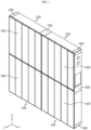
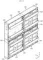
- FIG. 1 is a perspective view showing a battery pack according to an embodiment of the present disclosure.
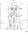
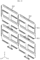
- FIG. 2 is a view separately showing some configurations of a battery pack according to an embodiment of the present disclosure.
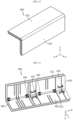
- FIGS. 3 and 4 are perspective views showing a coupling member of a battery pack according to an embodiment of the present disclosure.
- a battery pack according to an embodiment of the present disclosure may include a battery module 100, a processing unit 200, and a first coupling member 600.
- the battery module 100 may include a first corner 111 formed by two side plates and a first opening 112 formed at the first corner 111.
- the battery module 100 may have a rectangular parallelepiped shape.
- the housing 110 may form the appearance of the battery module 100.
- the housing 110 of the battery module 100 may include a front plate and four side plates.
- the four side plates of the housing 110 may form four corners 111.
- the four corners may be configured in a shape of chamfering.
- the corner 111 may be a plate connecting two side plates.
- the corner 111 may be formed by two side plates.
- the corner 111 may have an opening 112.
- the opening 112 may be open in the forward or X-axis direction.
- the four corners 111 may have substantially the same shape.
- the battery module 100 may include a plurality of battery cells therein.
- the battery cell may be a secondary battery.
- the battery module 100 may charge power to the battery cells or discharge power from the battery cells to the outside.
- the battery pack may be composed of a plurality of battery modules 100.
- the battery pack may include three battery modules 100.
- the processing unit 200 is located on one side of the battery module 100 and controls charge/discharge of the battery module 100, and may include a second corner 211 adjacent to the first corner 111 and a second opening 212 formed at the second corner 211.
- the processing unit 200 may have a rectangular parallelepiped shape.
- the housing 210 may form the appearance of the processing unit 200. Appearances or sizes of the processing unit 200 and the battery module 100 may be configured to be very similar or substantially the same.
- the housing 210 of the processing unit 200 may include a front plate and four side plates. Also, the four side plates of the housing 210 may form four corners 211.
- the four corners 211 may be configured in a shape of chamfering. Alternatively, the corner 211 may be a plate connecting two side plates.
- the corner 211 may be formed by two side plates.
- the corner 211 may have an opening 212.
- the opening 212 may be open in the forward or X-axis direction.
- the four corners 211 may have substantially the same shape.
- the battery module 100 may include a plurality of battery cells therein. In this case, the battery cell may be a secondary battery.
- the processing unit 200 may be electrically linked, connected, or coupled to a plurality of battery modules 100.
- the processing unit 200 may control charge/discharge of the battery module 100.
- the processing unit 200 may detect and obtain status information of the battery module 100.
- the battery pack may be configured to include a plurality of processing units 200 to control a plurality of battery modules 100.
- the battery pack may include three battery modules 100 and one processing unit 200.
- Three battery modules 100 and one processing unit 200 may be electrically connected to each other.
- the processing unit 200 may control charge/discharge of the three battery modules 100, and may obtain or detect status information such as voltage or temperature of the three battery modules 100.
- Each corner 111 of the battery module 100 and each corner 211 of the processing unit 200 may be configured to have substantially the same shape.
- the first coupling member 600 may be configured to have one side fastened to the first corner 111 and the other side fastened to the second corner 211.
- the coupling member 600 may be configured in plurality. For example, referring to FIG. 3 , two coupling members 600 may be fastened to the battery module 100 and the processing unit 200. The two coupling members 600 may physically connect, couple, or fasten the battery module 100 and the processing unit 200.
- the coupling member 600 may physically connect, couple, or fasten two neighboring battery modules 100. Also, the coupling member 600 may physically connect, couple, or fasten two neighboring processing units 200. In addition, the coupling member 600 may physically connect, couple, or fasten the neighboring battery module 100 and the processing unit 200.
- the coupling member 600 may include a first part 610, a second part 620, a third part 630, a fourth part 640, and a fifth part 650.
- the second part 620 may extend in the +Z-axis direction from the first part 610 and then be bent to extend in the +X-axis direction.
- the third part 630 may extend in the +X-axis direction from the second part 620.
- the fourth part 640 may extend in the +X-axis direction from the third part 630 and then be bent to extend in the -Z-axis direction.
- the fifth part 650 may extend in the +X-axis direction from the fourth part 640.
- the second hole 603 may be formed in the first part 610.
- the holes 601 may be formed in the second part 620 and the fourth part 640, respectively.
- the hole 602 may be formed in the fifth part 650.
- the hole 602 may be a long hole extending along the X-axis direction.
- the hole 602 may have a shape open in the +X-axis direction.
- the coupling member 600 may stably connect, couple, or fasten the battery module 100 and the processing unit 200 constituting the battery pack.
- the battery pack may include one or more battery modules 100 and one or more processing units 200 in various combinations.
- the positional relationship or coupling relationship of the battery module 100 and the processing unit 200 constituting the battery pack may be configured in various ways. Accordingly, it may be configured to flexibly correspond to the amount of power or output variously required for the battery pack.
- the external shape of the battery pack is configured to be variously deformable, it may be freed from restrictions of a space in which the battery pack is installed.
- a battery pack may include a double corner cover 500.
- the corner cover 500 may cover the first opening 112 and the second opening 212.
- the corner cover 500 may also be referred to as a double corner cover 500.
- the double corner cover 500 may be provided at a portion where the corner 111 of the battery module 100 and the corner 211 of the processing unit 200 are adjacent.
- the double corner cover 500 may be provided at a portion where the two corners 111, 211 are adjacent.
- the two neighboring corners 111, 211 may be the corner 111 of the battery module 100 or the corner 211 of the processing unit 200.
- the two neighboring corners 111 may be the corners 111 of the battery modules 100 that are adjacent to each other.
- the two neighboring corners 211 may be the corners 211 of the neighboring processing units 200.
- the battery pack may include two double corner covers 500 covering the corners 111, 211 formed by the processing unit 200 and the neighboring battery module 100, and two double corner covers 500 covering the corners 111 formed by two neighboring battery modules 100.
- the double corner cover 500 may protect the internal configuration of the battery pack by covering the corner 111 of the neighboring battery module 100, the corner 211 of the neighboring processing unit 200, or the corner 211 of the neighboring battery module 100 and the processing unit 200.
- the battery module 100 and the processing unit 200 may have openings 112, 212 to be connected to an external configuration, and when the openings 112, 212 are exposed to the outside, the inside thereof may be damaged by penetration of foreign substances.
- the double corner cover 500 may protect the inside of the battery module 100 or the processing unit 200 by covering the openings 112, 212. As a result, the safety and life of the battery pack may be improved.
- the double corner cover 500 may prevent sunlight from penetrating into the battery module 100 or the processing unit 200 through the openings 112, 212. As a result, the safety and life of the battery pack may be improved.
- FIG. 5 is an enlarged view of portion A of FIG. 2 .
- the battery pack according to an embodiment of the present disclosure may further include a cable 700 passing through at least one of the first opening 112 and the second opening 212, and the double corner cover 500 may be configured to cover the cable 700.
- the cable 700 may electrically connect the battery module 100 and the processing unit 200. In addition, the cable 700 may electrically connect the two battery modules 100. Also, when the battery pack includes a plurality of processing units 200, the cable 700 may electrically connect the two processing units 200.
- the cable 700 may be configured in plurality.
- the cable 700 may transmit power or signals.
- One or more battery modules 100 and one or more processing units 200 constituting the battery pack may be arranged in various forms.
- the cable 700 may be configured to pass through the openings 112, 212 formed at the corners 111, 211 in which the battery module 100 and the processing unit 200 are easily electrically connected.
- the cable 700 may pass through the openings 112, 212 formed at the corners 111, 211 of either the battery module 100 or the processing unit 200, and may pass through the openings 112, 212 formed at the corners 111, 211 of either the other battery module 100 or the other processing unit 200.
- the double corner cover 500 may cover the cable 700.
- the cable 700 and the openings 112, 212 may be covered by the double corner cover 500.
- the double corner cover 500 may prevent foreign substances from penetrating the cable 700 by covering the cable 700.
- the double corner cover 500 may prevent the cable 700 from being damaged by sunlight by covering the cable 700. As a result, the safety and life of the battery pack may be improved.
- FIG. 6 is a view of a corner cover of a battery pack according to an embodiment of the present disclosure as viewed from the outside.
- FIG. 7 is a view of a corner cover of a battery pack according to an embodiment of the present disclosure as viewed from the inside.
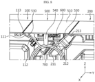
- FIG. 8 is a view showing that a corner cover of a battery pack according to an embodiment of the present disclosure is coupled to a battery module and a processing unit.
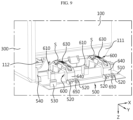
- FIG. 9 is a view showing that a corner cover of a battery pack according to an embodiment of the present disclosure is coupled to a coupling member.
- FIG. 10 is an enlarged view of a corner cover of a battery pack according to an embodiment of the present disclosure.
- a corner cover of a battery pack may be configured in the form of a flat plate.
- the double corner cover may include a plate, and the plate may have a flat shape.
- the double corner cover may connect the side plates of two neighboring battery modules.
- the double corner cover may connect the side plates of two neighboring processing units.
- the double corner cover may connect the side plate of the neighboring battery module and the side plate of the processing unit.
- the double corner cover may prevent foreign substances from penetrating by covering a space between neighboring battery modules, between neighboring processing units, or between the neighboring battery module and the processing units. As a result, the safety and life of the battery pack may be improved.
- the corner cover 500 of the battery pack may include a first hook 520 formed on an inner surface and coupled to the coupling member 600.
- the double corner cover 500 may include a first hook 520 protruding toward the inside of the plate 510.
- the first hook 520 may be formed in plurality. Two pairs of first hooks 520 may be fastened to one coupling member 600. Alternatively, two pairs of first hooks 520 may be fastened to the first part 610 and the fifth part 650, respectively.
- the double corner cover 500 may include four pairs of first hooks 520. Two pairs of first hooks 520 may be fastened to each of the two coupling members 600.
- the double corner cover 500 may be easily hookedly coupled to the coupling member 600 without a separate fastening member. As a result, the assemblability and productivity of the battery pack may be improved.
- the corner cover 500 of the battery pack may include a second hook 530 formed on an inner surface and coupled to the first opening 112 or the second opening 212.
- the double corner cover 500 may include a second hook 530 protruding toward the inside of the plate 510.
- the second hook 530 may be formed in plurality.
- the double corner cover 500 may include a second hook 530 fastened to the first opening 112 and a second hook 530 fastened to the second opening 212.
- the double corner cover 500 may be easily hookedly coupled to the battery module 100 or the processing unit 200 without a separate fastening member. As a result, the assemblability and productivity of the battery pack may be improved.
- the battery module 100 of the battery pack may further include a first stepped portion 113 formed at the first corner 111.
- the processing unit 200 may further include a second stepped portion 213 formed at the second corner 211.
- the corner cover 500 may be seated on the first stepped portion 113 and the second stepped portion 213.
- the first stepped portion 113 may be formed at both sides of the first corner 111.
- the first stepped portion 113 may be formed inside the side plate forming the first corner 111.
- the step of the first stepped portion 113 may be formed to be substantially equal to the thickness of the plate 500 of the double corner cover 500.
- the second stepped portion 213 may be formed at both sides of the second corner 211.
- the second stepped portion 213 may be formed inside the side plate forming the second corner 211.
- the step of the second stepped portion 213 may be formed to be substantially equal to the thickness of the plate 510 of the double corner cover 500.
- the plate 510 of the double corner cover 500 may be seated on the first stepped portion 113 and the second stepped portion 213.
- the first stepped portion 113 and the second stepped portion 213 may support the plate 510.
- the double corner cover 500 may be seated on the first stepped portion 113 and the second stepped portion 213, thereby maintaining a stable coupling state with the battery module 100 or the processing unit 200. As a result, the stability of the battery pack may be improved.
- the battery pack may further include a first front cover 300 and a second front cover 300.
- the first front cover 300 may be provided on the front surface of the battery module 100. Alternatively, the first front cover 300 may be fastened or coupled to the front plate or front surface of the battery module 100. The first front cover 300 may have a larger area than the front surface or front plate of the battery module 100.
- the battery module 100 may have a port 120 on the front surface or front plate. A cable 700 may be connected to the port 120.
- the battery module 100 may be electrically connected to another neighboring battery module 100 or processing unit 200 through the port 120.
- the first front cover 300 may cover the port 120 and the cable 700 connected to the port 120.
- the second front cover 300 may be provided on the front surface of the processing unit 200. Alternatively, the second front cover 300 may be fastened or coupled to the front plate or front surface of the processing unit 200. The second front cover 300 may have a larger area than the front surface or front plate of the processing unit 200.
- the processing unit 200 may have a port 220 on the front surface or front plate. A cable 700 may be connected to port 220.
- the processing unit 200 may be electrically connected to an adjacent battery module 100 or another processing unit 200 through the port 220.
- the second front cover 300 may cover the port 120 and the cable 700 connected to the port 220.
- the first front cover 300 and the second front cover 300 may be configured to have substantially the same shape and structure.
- At least one of the first front cover 300 and the second front cover 300 may cover the front side of the double corner cover 500.
- the first front cover 300 and the second front cover 300 may cover the front side of the double corner cover 500.
- the first front cover 300 and the second front cover 300 may cover a space between the double corner cover 500 and the battery module 100 and a space between the double corner cover 500 and the processing unit 200.
- the first front cover 300, the second front cover 300, and the double corner cover 500 may prevent foreign substances from penetrating by covering a space between neighboring battery modules 100, between neighboring processing units 200, or between the neighboring battery module and the processing unit 200. As a result, the safety and life of the battery pack may be improved.
- the corner cover 500 of the battery pack may include a support portion 540 provided on the front side and supporting the rear surface of the first front cover 300 or the second front cover 300.
- the support portion 540 may protrude toward the inside of the plate 510.
- the support portion 540 may be formed on the front side of the plate 510.
- the support portion 540 may support a portion where the first front cover 300 and the second front cover 300 are adjacent.
- a portion of the support portion 540 may support the rear surface of the first front cover 300, and a portion of the support portion 540 may support the rear surface of the second front cover 300.
- the first front cover 300 and the second front cover 300 may be stably coupled by the double corner cover 500.
- the rigidity or stability of the battery pack may be improved.
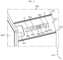
- FIG. 11 is a perspective view showing a corner of a battery pack according to an embodiment of the present disclosure.
- a coupling member may be fastened to a corner 211 of a battery pack according to an embodiment of the present disclosure.
- the corners 111, 211 may be the corner 111 of the battery module 100 or the corner 211 of the processing unit 200.
- the corners 111, 211 may be the corner 111 of the battery module 100 or the corner 211 of the processing unit 200 located at the outermost portion of the battery pack.
- the coupling member 600 may be fastened to the corners 111, 211. Both sides of the coupling member 600 may be fastened to the corners 111, 211 by the fastening member S.
- both sides of the coupling member 600 may be fastened to the corner 211 of the processing unit 200 through holes 602, 603.
- FIG. 12 is a perspective view showing a corner cover 400 of a battery pack according to an embodiment of the present disclosure.
- FIG. 13 is a perspective view of an inner surface of a corner cover 400 of a battery pack according to an embodiment of the present disclosure.
- a battery pack according to an embodiment of the present disclosure may include a corner cover 400.
- the corner cover 400 may be referred to as a single corner cover 400.
- the single corner cover 400 may have a bent plate shape.
- the single corner cover 400 may include a first part 410 and a second part 420.
- the first part 410 and the second part 420 may form a bent plate shape.
- the first part 410 and the second part 420 may be connected vertically.
- the single corner cover 400 may be coupled to any one of the four corners 111, 211 of the battery module 100 or the processing unit 200.
- the single corner cover 400 may include a guide 430 and a hook 440 protruding from the inner surface.
- the guide 430 may be provided as a pair.
- the hook 440 may be provided in two pairs.
- a pair of guides 430 may be provided on the first part 410 and the second part 420, respectively.
- Two pairs of hooks 440 may be provided on the first part 410 and the second part 420, respectively.
- the single corner cover 400 may include a protrusion 450 protruding toward the front side.
- the protrusion 450 may be formed across the first part 410 and the second part 420.
- the single corner cover 400 may have a groove 460 formed on the rear side.
- the groove 460 may be formed across the first part 410 and the second part 420.
- FIG. 14 is a view showing the coupling of a corner cover 400 of a battery pack according to an embodiment of the present disclosure and a coupling member 600.
- the hook 440 may be fastened to the coupling member 600.
- the hook 440 may be fastened to the hole 601 of the coupling member 600.
- the hole 601 of the coupling member 600 may be formed as a pair.
- a pair of hooks 440 may be fastened to one hole 601.
- the coupling member 600 may be positioned between the pair of guides 430.
- the single corner cover 400 may be slid forward and backward after being hookedly coupled to the coupling member 600.
- the guide 430 may guide the sliding of the single corner cover 400 along the coupling member 600.
- the single corner cover 400 may be easily hookedly coupled to the coupling member 600 without a separate fastening member. As a result, the assemblability and productivity of the battery pack may be improved.
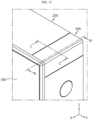
- FIG. 15 is a view showing that a corner cover 400 is coupled to a corner 111, 112 of a battery pack according to an embodiment of the present disclosure.
- FIG. 16 is a view showing a portion of a cross-sectional configuration along the cutting line B-B' in FIG. 15 .
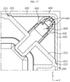
- FIG. 17 is a view showing a portion of a cross-sectional configuration along the cutting line C-C' in FIG. 15 .
- the single corner cover 400 of the battery pack according to an embodiment of the present disclosure may slidingly move to contact or adhere to the front cover 300.
- the protrusion 450 of the single corner cover 400 may be inserted into the front cover 300.
- the single corner cover 400 may include a seating portion 411 formed along an edge of the first part 410.
- the single corner cover 400 may include a seating portion 421 formed along an edge of the second part 420.
- the seating portions 411, 421 of the single corner cover 400 may be seated on the stepped portion 213 of the corner 211.
- the stepped portion 213 may support the seating portions 411, 421 of the single corner cover 400.
- the single corner cover 400 may cover the opening 212 of the corner 211.
- the single corner cover 400 may be seated on the first stepped portion 113 and the second stepped portion 213, thereby maintaining a stable coupling state with the battery module 100 or the processing unit 200. As a result, the stability of the battery pack may be improved.
- the battery module 100 and the processing unit 200 may have openings 112, 212 to be connected to an external configuration, and when the openings 112, 212 are exposed to the outside, the inside may be damaged by the penetration of foreign substances.
- the single corner cover 400 may protect the inside of the battery module 100 or the processing unit 200 by covering the openings 112, 212. As a result, the safety and life of the battery pack may be improved.
- FIG. 18 is a perspective view of a battery pack according to an embodiment of the present disclosure as viewed from the rear.
- FIG. 19 is a view showing a wall mount bracket 810 of a battery pack according to an embodiment of the present disclosure.
- a battery pack according to an embodiment of the present disclosure may include a coupling bar 820.
- the coupling bar 820 may be provided in the battery module 100 or the processing unit 200, respectively.
- Each of the battery module 100 or the processing unit 200 may include two coupling bars 820.
- the coupling bar 820 may be provided on or fastened to the rear surface of the battery module 100 or the processing unit 200.
- the two coupling bars 820 provided on the rear surface of the battery module 100 may be disposed side by side.
- the two coupling bars 820 provided on the rear surface of the processing unit 200 may be disposed side by side.
- a battery pack may include a wall mount bracket 810.
- the wall mount bracket 810 may be installed on a structure such as a wall or a fixture such as an outer wall of a building.
- the wall mount bracket 810 may include a hanging portion 811.
- the coupling bar 820 of the battery module 100 or the coupling bar 820 of the processing unit 200 may be hooked or coupled to the hanging portion 811.
- the wall mount brackets 810 may be provided in plurality.
- the wall mount brackets 810 may be provided in a number equal to the sum of the number of battery modules 100 and the number of processing units 200.
- the wall mount bracket 810 may be provided in one-to-one correspondence with the battery module 100 and the processing unit 200.
- the wall mount bracket 810 may be provided to correspond to the number of battery modules 100 or processing units 200 provided in the battery pack. This may facilitate installation on a wall or structure, even if the configuration or shape of the battery pack is diversified.
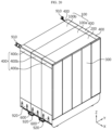
- FIG. 20 is a perspective view showing a battery pack according to an embodiment of the present disclosure.
- FIG. 21 is a view separately showing some configurations of a battery pack according to an embodiment of the present disclosure.
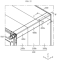
- FIG. 22 is an enlarged view showing some configurations of a battery pack according to an embodiment of the present disclosure.
- a battery pack according to an embodiment of the present disclosure may include a battery module 100, a processing unit 200, and a corner cover 400.
- the battery module 100 may include a first corner 111 formed by two side plates and a first opening 112 formed in the first corner 111.
- the battery module 100 may have a rectangular parallelepiped shape.
- the housing 110 may form the appearance of the battery module 100.
- the housing 110 of the battery module 100 may include a front plate and four side plates.
- the four side plates of the housing 110 may form four corners 111.
- the four corners may be configured in a shape of chamfering.
- the corner 111 may be a plate connecting two side plates.
- the corner 111 may be formed by two side plates.
- the corner 111 may have an opening 112.
- the opening 112 may be open in the forward or X-axis direction.
- the four corners 111 may have substantially the same shape.
- the battery module 100 may include a plurality of battery cells therein.
- the battery cell may be a secondary battery.
- the battery module 100 may charge power to the battery cells or discharge power from the battery cells to the outside.
- the battery pack may be composed of a plurality of battery modules 100.
- the battery pack may include two battery modules 100a, 100b.
- the processing unit 200 is located on front side of the battery module 100a and controls charge/discharge of the battery module 100, and may include a second corner 211 adjacent to the first corner 111 and a second opening 212 formed at the second corner 211.
- the processing unit 200 may have a rectangular parallelepiped shape.
- the housing 210 may form the appearance of the processing unit 200. Appearances or sizes of the processing unit 200 and the battery module 100 may be configured to be very similar or substantially the same.
- the housing 210 of the processing unit 200 may include a front plate and four side plates. Also, the four side plates of the housing 210 may form four corners 211.
- the four corners 211 may be configured in a shape of chamfering. Alternatively, the corner 211 may be a plate connecting two side plates.
- the corner 211 may be formed by two side plates.
- the corner 211 may have an opening 212.
- the opening 212 may be open in the forward or X-axis direction.
- the four corners 211 may have substantially the same shape.
- the processing unit 200 may be electrically linked, connected, or coupled to a plurality of battery modules 100.
- the processing unit 200 may control charge/discharge of the battery module 100.
- the processing unit 200 may detect and obtain status information of the battery module 100.
- the battery pack may be configured to include a plurality of processing units 200 to control a plurality of battery modules 100.
- the battery pack may include two battery modules 100 and one processing unit 200.
- Two battery modules 100 and one processing unit 200 may be electrically connected to each other.
- the processing unit 200 may control charge/discharge of the two battery modules 100, and may obtain or detect status information such as voltage or temperature of the two battery modules 100.
- Each corner 111 of the battery module 100 and each corner 211 of the processing unit 200 may be configured to have substantially the same shape.
- the corner cover 400 may be coupled to the corner 211 of the processing unit 200. Also, the corner cover 400 may cover the opening 212 of the processing unit 200.
- the corner cover 400 may be referred to as a single corner cover 400.
- the single corner cover 400 may be configured to be coupled to any of the four corners 111 of the battery module 100 and the four corners 211 of the processing unit 200.
- the battery pack may include one or more battery modules 100 and one or more processing units 200 in various combinations.
- the positional relationship or coupling relationship of the battery module 100 and the processing unit 200 constituting the battery pack may be configured in various ways. Accordingly, it may be configured to flexibly correspond to the amount of power or output variously required for the battery pack.
- the external shape of the battery pack is configured to be variously deformable, it may be freed from restrictions of a space in which the battery pack is installed.
- the single corner cover 400 may protect the internal configuration of the battery pack by covering the corner 111 of the neighboring battery module 100 and the corner 211 of the processing unit 200.
- the battery module 100 and the processing unit 200 may have openings 112, 212 to be connected to an external configuration, and when the openings 112, 212 are exposed to the outside, the inside thereof may be damaged by penetration of foreign substances.
- the single corner cover 400 may protect the inside of the battery module 100 or the processing unit 200 by covering the openings 112, 212. As a result, the safety and life of the battery pack may be improved.
- the single corner cover 400 may prevent sunlight from penetrating into the battery module 100 or the processing unit 200 through the openings 112, 212. As a result, the safety and life of the battery pack may be improved.
- FIG. 23 is an enlarged view separately showing some configurations of a battery pack according to an embodiment of the present disclosure.
- the battery pack according to an embodiment of the present disclosure may further include a cable 700 passing through the opening 212 and electrically connecting the battery module 100 and the processing unit 200.
- the cable 700 may electrically connect the battery module 100 and the processing unit 200. In addition, the cable 700 may electrically connect the two battery modules 100. Also, when the battery pack includes a plurality of processing units 200, the cable 700 may electrically connect the two processing units 200.
- the cable 700 may be configured in plurality.
- the cable 700 may transmit power or signals.
- One or more battery modules 100 and one or more processing units 200 constituting the battery pack may be arranged in various forms.
- the cable 700 may be configured to pass through the openings 112, 212 formed at the corners 111, 211 in which the battery module 100 and the processing unit 200 are easily electrically connected.
- the cable 700 may pass through the openings 112, 212 formed at the corners 111, 211 of either the battery module 100 or the processing unit 200, and may pass through the openings 112, 212 formed at the corners 111, 211 of either the other battery module 100 or the other processing unit 200.
- the single corner cover 400 may cover the cable 700.
- the cable 700 and the openings 112, 212 may be covered by the single corner cover 400.
- the single corner cover 400 may prevent foreign substances from penetrating the cable 700 by covering the cable 700.
- the single corner cover 400 may prevent the cable 700 from being damaged by sunlight by covering the cable 700. As a result, the safety and life of the battery pack may be improved.
- the battery pack may include a stand 920.
- the stand 920 may be provided in each of the processing unit 200 or the battery module 100.
- the plurality of stands 920 may be connected, coupled, or fastened to each other by the coupling member 600.
- the stand 920 may increase the height of the battery pack.
- the battery pack When the battery pack is installed outdoors or on the ground, the battery pack may be damaged by rainwater or the like.
- the battery pack may protect the battery module 100 or the processing unit 200 by including the stand 920.
- the battery module 100 of the battery pack may be located at the rear of the processing unit 200.
- the battery pack may include a coupling member 600 having one side fastened to the corner 211 of the processing unit 200 and the other side fastened to the corner 111 of the battery module 100.
- the battery module 100 may be provided in plurality.
- the first battery module 100a may be located at the rear of the processing unit 200.
- the second battery module 100b may be located at the rear of the first battery module 100a.
- the coupling member 600a may couple the processing unit 200 and the first battery module 100a.
- the coupling member 600b may couple the first battery module 100a and the second battery module 100b.
- One side and the other side of the coupling member 600 may be fastened to the corners 111, 211 by the fastening member S.
- the coupling member 600 may be configured to be fastened to any of the four corners of the battery module 100 and the four corners of the processing unit 200.
- one side of the coupling member 600a may be fastened to the corner 211 of the processing unit 200, and the other side thereof may be fastened to the corner 111 of the first battery module 100a.
- one side of the coupling member 600b may be fastened to the corner 111 of the first battery module 100a, and the other side thereof may be fastened to the corner 111 of the second battery module 100b.
- the coupling member 600 may stably connect, couple or fasten the battery module 100 and the processing unit 200 constituting the battery pack.
- the battery pack may include a front cover 300 provided on the front surface of the processing unit 200 and covering the front side of the corner cover 400.
- the front cover 300 may be provided on the front surface of the processing unit 200. Alternatively, the front cover 300 may be fastened or coupled to the front plate or the front surface of the processing unit 200. The front cover 300 may have a larger area than the front surface or the front plate of the processing unit 200.
- the processing unit 200 may have a port 220 on the front surface or front plate.
- the cable 700 may be connected to port 220.
- the processing unit 200 may be electrically connected to an adjacent battery module 100 or another processing unit 200 through the port 220.
- the front cover 300 may cover the port 220 and the cable 700 connected to the port 220.
- the front cover 300 may cover the front side of the single corner cover 400.
- the front cover 300 may cover a space between the single corner cover 400 and the corner 211 of the processing unit 200.
- the front cover 300 may prevent foreign substances from penetrating by covering a space between the single corner cover 400 and the corner 211 of the processing unit 200. As a result, the safety and life of the battery pack may be improved.
- FIG. 24 is a view showing a portion of a cross-sectional configuration along the cutting line D-D' in FIG. 22 .
- the corner cover 400 of the battery pack may include a protrusion 450 protruding toward the front side and inserted into the front cover 300.
- the single corner cover 400 may include a protrusion 450 protruding toward the front side.
- the protrusion 450 may be formed across the first part 410 and the second part 420.
- the front cover 300 may form a space.
- the protrusion 450 may be inserted into the space formed by the front cover 300. Alternatively, it may be inserted into the inside of the front cover 300.
- the protrusion 450 may block the gap between the front cover 300 and the single corner cover 400, and prevent foreign substances from penetrating into the gap between the front cover 300 and the single corner cover 400. As a result, the safety and life of the battery pack may be improved.
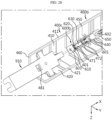
- FIG. 26 is a view showing a corner cover 400 of a battery pack according to an embodiment of the present disclosure.
- the corner cover 400 may be coupled to the coupling member 600 so as to slide in the front and rear directions.
- the single corner cover 400 may slidingly move to contact or adhere to the front cover 300.
- the protrusion 450 of the single corner cover 400 may be inserted into the front cover 300.
- the battery module 100 and the processing unit 200 may have openings 112, 212 to be connected to an external configuration, and when the openings 112, 212 are exposed to the outside, the inside may be damaged by the penetration of foreign substances.
- the single corner cover 400 may effectively block a gap through which foreign substances may penetrate into the battery pack. As a result, the inside of the battery module 100 or the processing unit 200 may be protected, and the safety and life of the battery pack may be improved.
- FIG. 25 is a view showing a portion of a cross-sectional configuration along the cutting line E-E' in FIG. 22 .
- the single corner cover 400 of the battery pack may include a seating portion 411 formed along an edge of the first part 410.
- the single corner cover 400 may include a seating portion 421 formed along an edge of the second part 420.
- the seating portions 411, 421 of the single corner cover 400 may be seated on the stepped portion 213 of the corner 211.
- the stepped portion 213 may support the seating portions 411, 421 of the single corner cover 400.
- the single corner cover 400 may cover the opening 212 of the corner 211.
- the single corner cover 400 may be seated on the first stepped portion 113 and the second stepped portion 213, thereby maintaining a stable coupling state with the battery module 100 or the processing unit 200. As a result, the stability of the battery pack may be improved.
- the corner cover 400a may include hooks 471, 481 protruding from the inner surface and coupled to the coupling member 600a.
- the single corner cover 400a may have a bent plate shape.
- the single corner cover 400a may include a first part 410 and a second part 420.
- the first part 410 and the second part 420 may form a bent plate shape.
- the first part 410 and the second part 420 may be connected vertically.
- the hook 481 may be fastened to the hole 601 of the fourth part 640.
- the single corner cover 400a may include a first guide 482 and a first hook 481 protruding from the inner surface.
- the first guide 482 may be provided as a pair.
- the first hook 481 may be provided as a pair.
- a pair of first guides 482 may be provided in the first part 410 and the second part 420, respectively.
- a pair of first hooks 481 may be provided in the first part 410 and the second part 420, respectively.
- the single corner cover 400a may include a second guide 472 and a second hook 471 protruding from the inner surface.
- the second guide 472 may be provided as a pair.
- the second hook 471 may be provided as a pair.
- a pair of second guides 472 may be provided in the first part 410 and the second part 420, respectively.
- a pair of second hooks 471 may be provided in the first part 410 and the second part 420, respectively.
- the first hook 481 may be fastened to the coupling member 600a.
- the first hook 481 may be fastened to the hole 601 of the coupling member 600a.
- the hole 601 of the coupling member 600a may be formed as a pair.
- a pair of first hooks 481 may be fastened to one hole 601.
- the third part 630 of the coupling member 600a may be positioned between the pair of first guides 482.
- the single corner cover 400 may be slid in the front-rear direction or the X-axis direction after being hookedly coupled to the coupling member 600a.
- the hole 601 may be formed in the shape of a long hole so that the first guide 482 may slidingly move.
- the first guide 482 may guide the sliding of the single corner cover 400a along the coupling member 600a.
- the single corner cover 400a may be easily hookedly coupled to the coupling member 600a without a separate fastening member. As a result, the assemblability and productivity of the battery pack may be improved.
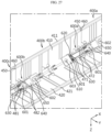
- FIG. 27 is a view showing a corner cover 400b of a battery pack according to an embodiment of the present disclosure.
- the corner cover 400b according to an embodiment of the present disclosure may include hooks 471, 481 protruding from the inner surface and coupled to the coupling members 600a, 600b.
- the second hook 471 may be fastened to the coupling member 600b.
- the second hook 471 may be fastened to the hole 601 of the coupling member 600a.
- the hole 601 of the coupling member 600a may be formed as a pair.
- a pair of second hooks 471 may be fastened to one hole 601.
- the third part 630 of the coupling member 600a may be positioned between the pair of second guides 472.
- the single corner cover 400b may be slid in the front-rear direction or the X-axis direction after being hookedly coupled to the coupling member 600a.
- the hole 601 may be formed in the shape of a long hole so that the second guide 472 may slidingly move.
- the second guide 472 may guide the sliding of the single corner cover 400b along the coupling member 600a.
- the coupling member 600a may have holes 602, 603 on one side and the other side.
- the coupling member 600 may be fastened to the corners 111, 211 by the fastening member S passing through the holes 602, 603.
- the hole 602 formed on one side may be open in the front side or the X-axis direction. Due to this shape, it may be easily fastened to the corners 111, 211 in response to tolerances arising in the production process of the battery module 100 and the processing unit 200.
- the single corner cover 400b may be easily hookedly coupled to the coupling member 600a without a separate fastening member. As a result, the assemblability and productivity of the battery pack may be improved.
- the battery pack may include a first corner cover 400a and a second corner cover 400b, wherein the first corner cover 400a may cover one side of the coupling member 600a and the second corner cover 400b may cover the other side of the coupling member 600a.
- the first corner cover 400a and the second corner cover 400b may be the same component or part.
- Two single corner covers 400a, 400b may be coupled to one coupling member 600a. Also, one coupling member 600a may be covered by two single corner covers 400a, 400b.
- the two single corner covers 400a, 400b are coupled to one coupling member 600a, and thus the number of components may be reduced. As a result, the assemblability and productivity of the battery pack may be improved.
- the first corner cover of the battery pack may include a groove formed on the rear side, and the second corner cover may include a second protrusion protruding toward the front side and inserted into the groove.
- the single corner covers 400a, 400b may have a groove 460 formed on the rear side.
- the groove 460 may be formed across the first part 410 and the second part 420.
- the groove 460 may have a shape corresponding to the protrusion 450.
- the second single corner cover 400b may slidingly move after being hookedly coupled to the coupling members 600a, 600b. Due to the sliding movement, the protrusion 450 of the second single corner cover 400b may be inserted into the groove 460 of the first single corner cover 400a.
- gaps between neighboring single corner covers 400a, 400b may be prevented.
- the processing unit 200 of the battery pack may have a first opening 212, and the battery module 100a may have a second opening 112.
- the battery pack may include a cable 700 passing through the first opening 212 and the second opening 112.
- the second corner cover 400b may cover the second opening 112 and the cable 700.
- the cable 700 may pass through the opening 212 of the processing unit 200 and the opening 112 of the battery module 100a.
- the single corner covers 400a, 400b may cover the corner 211 of the processing unit 200 and the corner 111 of the battery module 100a.
- the single corner covers 400a, 400b may cover the opening 212 of the processing unit 200 and the opening 112 of the battery module 100a.
- the single corner covers 400a, 400b may cover the coupling members 600a, 600b.
- the single corner covers 400a, 400b may cover the cable 700.
- the single corner covers 400a, 400b may prevent the corners 211, 111 of the processing unit 200 or the battery module 100a and the components adjacent to the corners 211, 111 from being exposed to the outside, and may prevent foreign substances from penetrating from the outside. As a result, the safety and life of the battery pack may be improved.
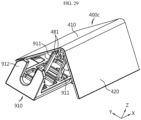
- FIG. 28 is a view showing a corner cover 400c of a battery pack according to an embodiment of the present disclosure.
- FIG. 29 is a view showing a corner cover 400c of a battery pack according to an embodiment of the present disclosure and an installation bracket 910.
- the battery pack according to an embodiment of the present disclosure may include an installation bracket 910.
- the installation bracket 910 may be fastened to the cover 111 of the battery module 100b by the fastening member S.
- the installation bracket 910 may fix the battery pack to a structure such as a wall.
- the installation bracket 910 may include a coupling portion 911.
- the hook 481 of the single corner cover 400c may be coupled to the coupling portion 911.
- the coupling portion 911 may be positioned between the guides 482 of the single corner cover 400c.
- the single corner cover 400c may cover at least a portion of the installation bracket 910.
- the plurality of battery modules 100, 100a, 100b described above are components having the same structure and shape, although different reference numerals are used for convenience of description.
- the coupling members 600, 600a, 600b are components having the same structure and shape, although different reference numerals are used for convenience of description.
- the single corner covers 400, 400a, 400b are components having the same structure and shape, although different reference numerals are used for convenience of description.
- An energy storage system includes one or more battery packs according to the present disclosure described above. Also, the energy storage system according to the present disclosure may further include general components included in the energy storage system in addition to the battery pack. In particular, the energy storage system according to the present disclosure may be a residential (building) energy storage system used to store energy in houses, buildings, or the like.
Landscapes
- Chemical & Material Sciences (AREA)
- Chemical Kinetics & Catalysis (AREA)
- Electrochemistry (AREA)
- General Chemical & Material Sciences (AREA)
- Engineering & Computer Science (AREA)
- Microelectronics & Electronic Packaging (AREA)
- Manufacturing & Machinery (AREA)
- Battery Mounting, Suspending (AREA)
- Secondary Cells (AREA)
Applications Claiming Priority (2)
| Application Number | Priority Date | Filing Date | Title |
|---|---|---|---|
| KR20210188568 | 2021-12-27 | ||
| PCT/KR2022/021258 WO2023128499A1 (fr) | 2021-12-27 | 2022-12-23 | Bloc-batterie |
Publications (2)
| Publication Number | Publication Date |
|---|---|
| EP4329079A1 true EP4329079A1 (fr) | 2024-02-28 |
| EP4329079A4 EP4329079A4 (fr) | 2025-05-14 |
Family
ID=86999815
Family Applications (1)
| Application Number | Title | Priority Date | Filing Date |
|---|---|---|---|
| EP22916640.0A Pending EP4329079A4 (fr) | 2021-12-27 | 2022-12-23 | Bloc-batterie |
Country Status (7)
| Country | Link |
|---|---|
| US (1) | US20240170791A1 (fr) |
| EP (1) | EP4329079A4 (fr) |
| JP (1) | JP7772314B2 (fr) |
| KR (1) | KR20230099673A (fr) |
| CN (1) | CN117957709A (fr) |
| AU (1) | AU2022427419A1 (fr) |
| WO (1) | WO2023128499A1 (fr) |
Cited By (1)
| Publication number | Priority date | Publication date | Assignee | Title |
|---|---|---|---|---|
| EP4290656A4 (fr) * | 2021-12-20 | 2025-03-26 | Lg Energy Solution, Ltd. | Bloc-batterie |
Family Cites Families (12)
| Publication number | Priority date | Publication date | Assignee | Title |
|---|---|---|---|---|
| JP5601960B2 (ja) * | 2010-10-14 | 2014-10-08 | 株式会社東芝 | 蓄電システム |
| JP5531938B2 (ja) * | 2010-12-09 | 2014-06-25 | 株式会社デンソー | 組電池 |
| CN103579678B (zh) | 2012-08-02 | 2015-04-22 | 深圳市格瑞普电池有限公司 | 易于安装的锂离子电池组 |
| DE102014216811B4 (de) | 2014-08-25 | 2022-03-10 | Robert Bosch Gmbh | Batteriemodulsystem |
| KR102021110B1 (ko) | 2016-01-08 | 2019-09-11 | 주식회사 엘지화학 | 배터리 팩 |
| KR102284340B1 (ko) * | 2016-01-19 | 2021-08-03 | 에스케이이노베이션 주식회사 | 배터리 팩 |
| JP6664513B2 (ja) | 2016-10-31 | 2020-03-13 | エルジー・ケム・リミテッド | バッテリーパック |
| KR102065103B1 (ko) * | 2016-11-04 | 2020-01-10 | 주식회사 엘지화학 | 배터리 팩 |
| KR102110543B1 (ko) * | 2017-03-22 | 2020-05-13 | 주식회사 엘지화학 | 배터리 팩 |
| KR102544785B1 (ko) * | 2018-12-18 | 2023-06-15 | 주식회사 엘지에너지솔루션 | 배터리 팩 및 이러한 배터리 팩을 포함하는 자동차 |
| CN212571186U (zh) | 2020-07-16 | 2021-02-19 | 天合光能股份有限公司 | 一种堆叠式电池系统 |
| US20240304929A1 (en) * | 2021-12-20 | 2024-09-12 | Lg Energy Solution, Ltd. | Battery pack |
-
2022
- 2022-12-23 CN CN202280041869.3A patent/CN117957709A/zh active Pending
- 2022-12-23 AU AU2022427419A patent/AU2022427419A1/en active Pending
- 2022-12-23 US US18/282,862 patent/US20240170791A1/en active Pending
- 2022-12-23 WO PCT/KR2022/021258 patent/WO2023128499A1/fr not_active Ceased
- 2022-12-23 JP JP2023577981A patent/JP7772314B2/ja active Active
- 2022-12-23 EP EP22916640.0A patent/EP4329079A4/fr active Pending
- 2022-12-23 KR KR1020220183788A patent/KR20230099673A/ko not_active Ceased
Cited By (1)
| Publication number | Priority date | Publication date | Assignee | Title |
|---|---|---|---|---|
| EP4290656A4 (fr) * | 2021-12-20 | 2025-03-26 | Lg Energy Solution, Ltd. | Bloc-batterie |
Also Published As
| Publication number | Publication date |
|---|---|
| US20240170791A1 (en) | 2024-05-23 |
| KR20230099673A (ko) | 2023-07-04 |
| WO2023128499A1 (fr) | 2023-07-06 |
| AU2022427419A1 (en) | 2024-01-18 |
| JP2024526130A (ja) | 2024-07-17 |
| JP7772314B2 (ja) | 2025-11-18 |
| CN117957709A (zh) | 2024-04-30 |
| EP4329079A4 (fr) | 2025-05-14 |
Similar Documents
| Publication | Publication Date | Title |
|---|---|---|
| EP3989355A1 (fr) | Module de batterie ayant une feuille ignifuge, bâti de batterie le comprenant et système de stockage d'énergie | |
| KR102946290B1 (ko) | 안전성이 향상된 배터리 팩 | |
| KR102047481B1 (ko) | 배터리 모듈 및 이를 포함하는 배터리 팩 | |
| KR102047480B1 (ko) | 배터리 모듈 및 이를 포함하는 배터리 팩 | |
| EP4175041B1 (fr) | Module de batterie, bloc-batterie et véhicule | |
| EP3557651B1 (fr) | Module de batterie comprenant une cartouche | |
| EP4016660A1 (fr) | Bâti de batterie ayant un cadre de fixation et appareil de stockage d'énergie | |
| EP4087047B1 (fr) | Module de batterie, bloc-batterie comprenant celui-ci et vehicule. | |
| EP4199175B1 (fr) | Bâti de batterie, dispositif de stockage d'énergie et dispositif de stockage de données | |
| US12525681B2 (en) | Battery module, battery pack, and vehicle | |
| EP4329079A1 (fr) | Bloc-batterie | |
| KR102947405B1 (ko) | 배터리 팩 | |
| EP4539227A1 (fr) | Bloc-batterie et dispositif le comprenant | |
| KR102774281B1 (ko) | 배터리 팩 | |
| KR20160096485A (ko) | 컴팩트 이차전지 모듈 | |
| KR20230099650A (ko) | 배터리 팩 | |
| EP4576384A1 (fr) | Bloc-batterie | |
| US20240234920A9 (en) | Battery pack and device including the same | |
| KR20230094182A (ko) | 배터리 모듈 |
Legal Events
| Date | Code | Title | Description |
|---|---|---|---|
| STAA | Information on the status of an ep patent application or granted ep patent |
Free format text: STATUS: THE INTERNATIONAL PUBLICATION HAS BEEN MADE |
|
| PUAI | Public reference made under article 153(3) epc to a published international application that has entered the european phase |
Free format text: ORIGINAL CODE: 0009012 |
|
| STAA | Information on the status of an ep patent application or granted ep patent |
Free format text: STATUS: REQUEST FOR EXAMINATION WAS MADE |
|
| 17P | Request for examination filed |
Effective date: 20231120 |
|
| AK | Designated contracting states |
Kind code of ref document: A1 Designated state(s): AL AT BE BG CH CY CZ DE DK EE ES FI FR GB GR HR HU IE IS IT LI LT LU LV MC ME MK MT NL NO PL PT RO RS SE SI SK SM TR |
|
| DAV | Request for validation of the european patent (deleted) | ||
| DAX | Request for extension of the european patent (deleted) | ||
| A4 | Supplementary search report drawn up and despatched |
Effective date: 20250416 |
|
| RIC1 | Information provided on ipc code assigned before grant |
Ipc: H01M 50/298 20210101ALI20250410BHEP Ipc: H01M 10/42 20060101ALI20250410BHEP Ipc: H01M 50/258 20210101ALI20250410BHEP Ipc: H01M 50/264 20210101ALI20250410BHEP Ipc: H01M 50/591 20210101ALI20250410BHEP Ipc: H01M 50/509 20210101ALI20250410BHEP Ipc: H01M 50/289 20210101ALI20250410BHEP Ipc: H01M 50/471 20210101AFI20250410BHEP |
|
| STAA | Information on the status of an ep patent application or granted ep patent |
Free format text: STATUS: EXAMINATION IS IN PROGRESS |
|
| 17Q | First examination report despatched |
Effective date: 20251022 |
|
| GRAP | Despatch of communication of intention to grant a patent |
Free format text: ORIGINAL CODE: EPIDOSNIGR1 |
|
| STAA | Information on the status of an ep patent application or granted ep patent |
Free format text: STATUS: GRANT OF PATENT IS INTENDED |
|
| INTG | Intention to grant announced |
Effective date: 20260311 |