EP4329087A1 - Dielektrische wellenleiterdatenschnittstelle und sensorsystem - Google Patents
Dielektrische wellenleiterdatenschnittstelle und sensorsystem Download PDFInfo
- Publication number
- EP4329087A1 EP4329087A1 EP22192337.8A EP22192337A EP4329087A1 EP 4329087 A1 EP4329087 A1 EP 4329087A1 EP 22192337 A EP22192337 A EP 22192337A EP 4329087 A1 EP4329087 A1 EP 4329087A1
- Authority
- EP
- European Patent Office
- Prior art keywords
- dielectric waveguide
- sensor system
- data interface
- dielectric
- mobile phone
- Prior art date
- Legal status (The legal status is an assumption and is not a legal conclusion. Google has not performed a legal analysis and makes no representation as to the accuracy of the status listed.)
- Pending
Links
Images


Classifications
-
- H—ELECTRICITY
- H01—ELECTRIC ELEMENTS
- H01P—WAVEGUIDES; RESONATORS, LINES, OR OTHER DEVICES OF THE WAVEGUIDE TYPE
- H01P3/00—Waveguides; Transmission lines of the waveguide type
- H01P3/16—Dielectric waveguides, i.e. without a longitudinal conductor
Definitions
- the present invention relates to a high-speed data interface and sensor system for IOT devices.
- the present invention relates to a dielectric waveguide data interface and sensor system, a mobile phone comprising such by the electric waveguide data interface and sensor system, several uses of such a system, a method of data transfer between two mobile devices, a method of sensing and positioning of an element in the environment of an IOT device using such a system or such a mobile phone, a program element and a computer-readable medium.
- Portable devices such as tablets, smart phones and smart watches have become popular recently due to the rapid advancement and low cost semi-conductor technologies.
- Portable devices as well as other electronic devices may incorporate antenna elements for radiofrequency (RF) communication as well as for radar applications such as object ranging, tracking and identification.
- RF radiofrequency
- multiple antenna elements may be utilized for beamforming, transmit diversity and multiple input, multiple output (MIMO) configurations, and also as radar sensors that can detect user motions, also known as gesture sensors.
- MIMO multiple input, multiple output
- portable devices may also need to acquire information about objects in their vicinity, such as sliding motions of fingers.
- a first aspect of the present disclosure relates to a dielectric waveguide data interface and sensor system, which comprises one or more dielectric waveguides and one or more radio transceivers attached to a first end of the respective dielectric waveguide.
- the radio transceiver comprises an electronic circuit, which is configured to generate a radar signal and/or a communication signal.
- a coupling element is provided, which is configured to couple the radar signal and/or the communication signal into the dielectric waveguide.
- This may provide for fast short range communication capabilities and object detection capabilities in close vicinity of a dielectric waveguide data interface and sensor system, i.e., in close vicinity of the dielectric waveguide.
- the dielectric waveguide data interface and sensor system provides alternative means of data exchange and can be manufactured at relatively low cost.
- Portable devices such as mobile phones, may also need to acquire information about objects on the side area of the mobile phone.
- the dielectric waveguide data interface and sensor system according to the present disclosure is capable of acquiring information about objects on the side area of a device and can be manufactured at low cost, at the same time improving functionality and increasing resilience and privacy of the device.
- a radio frequency system includes dielectric waveguides in the side region of the portable device.
- the dielectric waveguides are coupled to high-frequency circuits (electronic circuits) and may provide two functions: injecting electromagnetic waves into the dielectric waveguide and sensing electromagnetic waves coming from the dielectric waveguide.
- the dielectric waveguide may be constructed to carry electromagnetic waves partly inside the waveguide and partly outside the waveguide.
- High-frequency transceivers are attached to the ends of the dielectric waveguides to transmit and receive electromagnetic waves to and from the dielectric waveguides, respectively.
- the high-frequency transceivers are connected to the signal processing circuits of the portable device providing and receiving digital data for exchange between the portable device and other IOT devices, or to transmit and receive electrical signals from the immediate vicinity of the portable device.
- the electronic circuit and the coupling element are arranged on a transceiver substrate.
- the dielectric waveguide data interface and sensor system further comprises a load element attached to a second end of the dielectric waveguide, wherein the load element is configured to absorb the radar signal after is has passed from the first end of the dielectric waveguide to the second end of the dielectric waveguide.
- the load element is a radio transceiver.
- the dielectric waveguide is filled with an outer dielectric material in which a channel formed of an inner dielectric material is embedded.
- the inner dielectric material is configured to guide the radar signal from the first end of the dielectric waveguide to the second end of the dielectric waveguide.
- the inner dielectric material has a higher or lower dielectric constant than the outer dielectric material.
- the outer dielectric material has a dielectric constant which is higher than one 1.5, or even higher than 2.
- Another aspect of the present disclosure relates to a mobile phone or another hand-held device, such as a tablet or a smart watch, comprising a first dielectric waveguide data interface and sensor system, as disclosed above and in the following.
- the mobile phone comprises, according to another embodiment, at least a second dielectric waveguide data interface and sensor system, such as described above and below, which is in the vicinity, i.e. adjacent to the first dielectric waveguide data interface and sensor system. These two may be arranged in a row.
- Another aspect of the present disclosure relates to the use of a dielectric waveguide data interface and sensor system, such as disclosed above and below, for data transfer between mobile devices or between a mobile device and a stationary device, or even between two stationary devices.
- Another aspect of the present disclosure relates to the use of such a dielectric waveguide data interface and sensor system or a mobile phone as health sensor.
- Another aspect of the present disclosure relates to the use of such a dielectric waveguide data interface and sensor system or a mobile phone as material sensor.
- a still further use relates to a dielectric waveguide data interface and sensor system or a mobile phone as length sensor.
- a further aspect relates to a method of data transfer, i.e. data transmission, between two mobile devices, in which both mobile devices are arranged side-by-side and data is transmitted between the two mobile devices or, more specifically, from one device to the other, using the above and below described dielectric waveguide data interface and sensor system.
- the method may further comprise the steps of applying a modulation scheme of a high-frequency signal when transmitting the data, and applying a demodulation scheme of the high-frequency signal when receiving the data (by the other device).
- a further aspect of the present disclosure relates to a method of sensing and positioning of an element in the environment, i.e. vicinity, of an IOT device using the above and below described dielectric waveguide data interface and sensor system or the above and below described mobile phone, for example by using a pulse radar method to detect reflected pulses from dielectric waveguide, or a frequency modulated radar method to detect reflected frequency spectrum from dielectric waveguide.
- a further aspect of the present disclosure relates to the use of the above and below described dielectric waveguide data interface and sensor system for blood pressure detection by placing dielectric waveguide data interface and sensor system next to a human body and detecting reflected radar signals from at least two dielectric waveguides and calculate pulse wave speed for deriving blood pressure value.
- a further aspect of the present disclosure relates to a program element which, when being executed by a processor of a dielectric waveguide data interface and sensor system or of a mobile device, such as a mobile phone, instructs the dielectric waveguide data interface and sensor system or the mobile device to perform the following steps: transmitting data between two mobile devices using the dielectric waveguide data interface and sensor system; sensing and positioning an element in an environment of an IOT device.
- a further aspect of the present disclosure relates to a computer-readable medium on which the above described program element is stored.
- a computer-readable medium may be a floppy disk, a hard disk, a CD, a DVD, an USB (Universal Serial Bus) storage device, a RAM (Random Access Memory), a ROM (Read Only memory) and an EPROM (Erasable Programmable Read Only Memory).
- a computer readable medium may also be a data communication network, e.g. the Internet, which allows downloading a program code.
- the recitation of "at least one of A, B and C” should be interpreted as one or more of a group of elements consisting of A, B and C, and should not be interpreted as requiring at least one of each of the listed elements A, B and C, regardless of whether A, B and C are related as categories or otherwise.
- the recitation of "A, B and/or C" or "at least one of A, B or C” should be interpreted as including any singular entity from the listed elements, e.g., A, any subset from the listed elements, e.g., A and B, or the entire list of elements A, B and C.
- Fig. 1 shows a perspective view of the housing of a mobile phone with four dielectric waveguides placed in the side walls. Seen from the outside, the mobile phone consists of the backplane 3 the display (not shown) and four side walls 1a-1d. According to the invention, there are several dielectric waveguide systems 2a, 2b placed in the side walls 1a and 1c. Because of the construction of the waveguide systems, they are touch sensitive and the position of a touch can be detected.
- Fig. 2 shows a top view of the mobile phone 100 in a user's hand. Visible are the fingers of the hand holding the mobile phone 100 with thumb 10, index finger 11, middle finger 12 and ring finger 13. The fingers are touching the dielectric waveguides with transceivers 2a and 2b. Because the waveguide systems 2a, 2b are touch sensitive, the position of the fingers can be detected and can be used as input signals for the mobile phone 100. Not only can the position of the fingers be detected, but also the movement of the fingers. For example, finger tapping can be a special form of input signals. Or, sliding of one finger can be used as input signal for loudness control. An advantage of this type of input operation is the possibility of one-hand operation of the mobile phone.
- One of the two mobile devices may also be a charging station, for example in a vehicle, or a tablet, or a display.
- magnets may be provided at the edges of the devices to facilitate firm contact between the two devices and to hold them together.
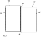
- Fig. 3 shows a top view of two mobile phones 100a and 100b placed near to each other so that some of the waveguide systems 2a, 2b are touching each other. Because of the construction of the waveguide systems 2a-2b, electromagnetic energy is outside the waveguide systems 2a, 2b and electrical coupling between them occurs. Therefore, it is possible to transfer electrical signals from one waveguide system to the other and this can be used for information transfer from first mobile phone 100 to second mobile phone 100' or vice versa.
- This type of information exchange has the advantage that it is very secure, since no information is emitted into the air, but only a coupling takes place in the extremely close range between the waveguide systems 2a, 2b of the two mobile phones.
- the information can be transmitted at a very high data rate, since the signals can be very broadband because no frequency regulations have to be observed since there is nearly no emission into the air.
- Fig. 4 shows a schematic view of a waveguide system with radio transceiver 5 and load element 6 placed at the ends of dielectric waveguide 4.
- the waveguide systems 2a, 2b consists of a dielectric waveguide 4 and radio transceiver 5 placed at the one end of dielectric waveguide 4 and a load element 6 placed at the other end of dielectric waveguide 4.
- the radio transceiver 5 is a high frequency electronic device with coupler structure capable of transmitting and receiving high frequency signals.
- the operation frequency in Millimeter wave range or in Terahertz range. This means, frequency is between 30 GHz and 3 THz or above. Higher frequency has the advantage of more compact construction because of shorter wavelength and hence smaller coupler size and smaller diameter of waveguide systems 2a and 2b.
- the radio transceiver 5 and load element 6 are glued to the ends of dielectric waveguide 4 or fixed to dielectric waveguide 4 with other means.
- the load element 6 consists of absorbing material and it prevents reflections from the end point of dielectric waveguide 4.
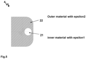
- Fig. 5 shows the cross section through dielectric waveguide 4.
- the dielectric waveguide 4 consists of at least two materials with different dielectric constants.
- the rod-shaped construction of dielectric waveguide 4 can take many forms.
- the dielectric waveguide 4 is composed of inner material 21 and outer material 22.
- the materials are insulators and have different dielectric constants epsilon1 and epsilon2 so that the waveguide can carry an electric wave. In most of the cases epsilon1 is greater than epsilon2.
- epsilon1 is greater than epsilon2.
- Fig. 6 shows schematic view of a radio transceiver 5. It consists of the transceiver substrate 31, an electronic circuit 32 and a coupling element 33.
- the transceiver substrate 31 is preferably a semiconductor material, for example monocrystalline Silicon.
- the coupling element 33 consists of metal and can have the shape of a rectangle forming a so-called patch-antenna.
- substrate materials for example Indium-Phosphide (InP) can also be used.
- a monolithic integrated transceiver is shown in the Fig. 6 .
- other integration methods are possible, for example two or more chip-solution, hybrid integration and different ICpackages can be used.
- the coupling element 33 can radiate to top-direction or through transceiver substrate 31 to the down-direction.
- the radio transceiver 5 is connected to other circuitry of the mobile phone 100 for example the main processor for data exchange.
- the electronic circuit 32 has the task of processing the data coming from processor or to deliver data to the processor.
- the electronic circuit 32 has the task of generating high-frequency signals and providing them to the dielectric waveguide 4 via coupling element 33 or to receive and process signals coming from dielectric waveguide 4 via coupling element 33.
- the first mode is the communication mode and the second mode is the sensing mode.
- the sensing mode is described first and the communication mode is described second.
- the radio transceiver 5 is acting similar to a common radar transceiver with the difference that in mobile phone 100 the generated radar signals from radio transceiver 5 go to dielectric waveguide 4 and in common radar it will go to air.
- Radar signals are well-known. Radar signals can be pulse signals or modulated high-frequency continuous wave signals. One example is the use of high frequency carrier at 300 GHz with linear frequency ramps of high bandwidth for example 50 GHz bandwidth to ensure sufficient local resolution.
- the signal in form of electromagnetic wave is coupled to dielectric waveguide 4 and the reflected signal is detected in radio transceiver 5. This procedure is known as FMCW radar (Frequency Modulated Continuous Wave). The reflection depends on environment of the dielectric waveguide 4.
- the dielectric waveguide 4 If the dielectric waveguide 4 is not touched, there will be no reflection because the load element 6 absorbs the electromagnetic wave at the end of dielectric waveguide 4. If something (for example a finger) touches the dielectric waveguide 4, then a reflection consisting of electromagnetic wave travelling back towards the radio transceiver 5 is generated. The time delay of transmission and receiving of electromagnetic wave is measured and the result is further processed. Because the time delay mentioned is depending on distance between radio transceiver 5 and the finger touching the dielectric waveguide 4. Hence, the exact position of the finger is detected. Not only position of one finger can be detected, but also position of several fingers. Similar to FMCW radar operation in air, the reflectivity spectrum over the whole length of the dielectric waveguide 4 can be estimated.
- the reflectivity properties over the whole length of the dielectric waveguide 4 can be estimated as well and hence, a plurality of touching points can be detected and its location can be determined.
- the functional principle can be pulse correlation basing on two slightly different pulse repetition frequencies f PRF1 and f PRF2 which trigger the TX and LO oscillators whereby their pulses drift apart from each other and so the measurement range is sequentially sampled.
- Another functional principle can be pulse correlation basing on controlled delay-elements in receive path to generate well-defined delay series corresponding to distance in dielectric waveguide 4.
- the contact pressure of soft surfaces can be measured. This can be used for different interesting use-cases. For example, when touching the dielectric waveguide 4 with a finger, the heart rate can be detected. Still more sensitive is the method of heart rate detection and heart sound detection when touching the dielectric waveguide 4 with an arm or with any other part of the body where a large pulse movement is palpable.
- two portable devices e.g. mobile phones are placed side by side as shown in Figure 3 .
- the placement is such that at least one dielectric waveguide 4 of the first mobile phone 100 touches at least one dielectric waveguide 4 of the second mobile phone 100'. It is assumed that the first mobile phone 100 should transmit information to the second mobile phone 100'.
- the radio transceiver 5 of the first mobile phone 100 transmits modulated high-frequency signal to waveguide system 2a. Because of touching dielectric waveguides, some of electromagnetic power carrying information is transferred to waveguide system 2b'.
- Figure 7 illustrates in more detail the process of data transfer. It shows an example of a flow chart to perform data transfer process. It is an embodiment of communication mode of two portable devices e.g. mobile phones.
- the boxes along the vertical line indicate the steps to initiate and execute data exchange between two mobile phones.
- a manual or automatic command is given to mobile phone 100 to synchronize data with another mobile phone 100'.
- the two mobile phones are placed side by side as shown in Figure 3 so that the dielectric waveguide 4 of the first mobile phone 100 touches dielectric waveguide 4 of the second mobile phone 100'.
- the radio transceiver 5 of the mobile phone 100' is activated in receive mode.
- the radio transceiver 5 of the first mobile phone 100 transmits data in form of modulated high-frequency signal to waveguide system 2a. Because of touching dielectric waveguides, some of electromagnetic power carrying information is transferred to waveguide system 2b' in step 205.
- the transferred data is stored in memory of mobile phone 100'.
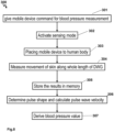
- Figure 8 shows a flow chart of blood pressure measurement process using mobile phone 100.
- the command for blood pressure measurement is given manually or according to health schedule of the user. This will activate the sensing mode in step 302.
- the mobile phone 100 is placed to human body at a spot on the body with a good pulse amplitude, for example at the wrist.
- the mobile phone 100 is placed parallel to the forearm in such a way that one of the dielectric waveguides 4 rests on the skin surface along its entire length.
- step 304 the movement of the skin surface along the length of dielectric waveguides 4 is measured.
- the movement of skin surface includes the pulse wave of periodic blood transport toward the hand of the user.
- the measurement is performed by rapidly determining the reflection conditions at all locations of the dielectric waveguide 4 and storing -in step 305- the results in memory.
- the measurement frequency can be in the range of some measurements per second till 1000 measurements per second.
- the stored information will be evaluated in step 306.
- Evaluation includes pulse shape and pulse wave velocity.
- the pulse shape will give indication for systolic to diastolic pressure ratio and pulse wave velocity will give indication for absolute values of blood pressure.
- the blood pressure values are available and will be displayed and/or stored in memory of mobile phone 100.
Landscapes
- Mobile Radio Communication Systems (AREA)
Priority Applications (1)
| Application Number | Priority Date | Filing Date | Title |
|---|---|---|---|
| EP22192337.8A EP4329087A1 (de) | 2022-08-26 | 2022-08-26 | Dielektrische wellenleiterdatenschnittstelle und sensorsystem |
Applications Claiming Priority (1)
| Application Number | Priority Date | Filing Date | Title |
|---|---|---|---|
| EP22192337.8A EP4329087A1 (de) | 2022-08-26 | 2022-08-26 | Dielektrische wellenleiterdatenschnittstelle und sensorsystem |
Publications (1)
| Publication Number | Publication Date |
|---|---|
| EP4329087A1 true EP4329087A1 (de) | 2024-02-28 |
Family
ID=83361041
Family Applications (1)
| Application Number | Title | Priority Date | Filing Date |
|---|---|---|---|
| EP22192337.8A Pending EP4329087A1 (de) | 2022-08-26 | 2022-08-26 | Dielektrische wellenleiterdatenschnittstelle und sensorsystem |
Country Status (1)
| Country | Link |
|---|---|
| EP (1) | EP4329087A1 (de) |
Citations (7)
| Publication number | Priority date | Publication date | Assignee | Title |
|---|---|---|---|---|
| EP0969545B1 (de) * | 1998-07-03 | 2005-01-26 | Murata Manufacturing Co., Ltd. | Richtkoppler, Antennenanordnung, und Sender-Empfänger |
| US20150295307A1 (en) * | 2014-04-09 | 2015-10-15 | Texas Instruments Incorporated | Dielectric Waveguide with Embedded Antenna |
| US20160240907A1 (en) * | 2015-02-12 | 2016-08-18 | Texas Instruments Incorporated | Dielectric Waveguide Radar Signal Distribution |
| WO2017171358A1 (ko) * | 2016-03-28 | 2017-10-05 | 한국과학기술원 | 전자기파 신호 전송을 위한 도파관 |
| EP3429025A1 (de) * | 2017-07-14 | 2019-01-16 | Nxp B.V. | Kabel, verfahren zur herstellung davon und zugehörige vorrichtung |
| US20200348395A1 (en) * | 2019-05-03 | 2020-11-05 | Commissariat à l'énergie atomique et aux énergies alternatives | Radio wave transceiver system |
| JP2021175168A (ja) * | 2020-04-30 | 2021-11-01 | キーコム株式会社 | 誘電体導波路 |
-
2022
- 2022-08-26 EP EP22192337.8A patent/EP4329087A1/de active Pending
Patent Citations (7)
| Publication number | Priority date | Publication date | Assignee | Title |
|---|---|---|---|---|
| EP0969545B1 (de) * | 1998-07-03 | 2005-01-26 | Murata Manufacturing Co., Ltd. | Richtkoppler, Antennenanordnung, und Sender-Empfänger |
| US20150295307A1 (en) * | 2014-04-09 | 2015-10-15 | Texas Instruments Incorporated | Dielectric Waveguide with Embedded Antenna |
| US20160240907A1 (en) * | 2015-02-12 | 2016-08-18 | Texas Instruments Incorporated | Dielectric Waveguide Radar Signal Distribution |
| WO2017171358A1 (ko) * | 2016-03-28 | 2017-10-05 | 한국과학기술원 | 전자기파 신호 전송을 위한 도파관 |
| EP3429025A1 (de) * | 2017-07-14 | 2019-01-16 | Nxp B.V. | Kabel, verfahren zur herstellung davon und zugehörige vorrichtung |
| US20200348395A1 (en) * | 2019-05-03 | 2020-11-05 | Commissariat à l'énergie atomique et aux énergies alternatives | Radio wave transceiver system |
| JP2021175168A (ja) * | 2020-04-30 | 2021-11-01 | キーコム株式会社 | 誘電体導波路 |
Similar Documents
| Publication | Publication Date | Title |
|---|---|---|
| CN108153410B (zh) | 用于基于雷达的姿态检测的方法和设备 | |
| US10218407B2 (en) | Radio frequency system and method for wearable device | |
| JP4164423B2 (ja) | センシング部とポインティングデバイスとを含み構成される装置 | |
| Trotta et al. | 2.3 SOLI: A tiny device for a new human machine interface | |
| US20210103031A1 (en) | Gesture recognition radar systems and methods | |
| US20260079247A1 (en) | Electronic Devices with Background-Cancelled Ultra Short Range Object Detection | |
| US20200241672A1 (en) | Detecting a Touch Input to a Surface | |
| CN107677990A (zh) | 一种定位装置及定位方法 | |
| US20170303858A1 (en) | Handheld biometric sensor for mobile devices | |
| US20170055938A1 (en) | Doppler Ultrasound Probe For Noninvasive Tracking Of Tendon Motion | |
| US20260050080A1 (en) | Electronic Devices with Non-Static Object Detection | |
| US12411223B2 (en) | Electronic devices with angular location detection capabilities | |
| US20240418853A1 (en) | Electronic Devices with Multi-Antenna Sensing | |
| Liu et al. | Analysis on a 77 GHz MIMO radar for touchless gesture sensing | |
| Rodrigues et al. | A novel microwave architecture for passive sensing applications | |
| CN113866761A (zh) | 一种体动的检测方法及装置 | |
| EP4329087A1 (de) | Dielektrische wellenleiterdatenschnittstelle und sensorsystem | |
| US12044769B2 (en) | Electronic devices with low signal-to-noise ratio range measurement capabilities | |
| Al‐Qudsi et al. | Scalable indoor positioning system with multi‐band FMCW | |
| US20250102656A1 (en) | Electronic Devices with Leakage-Based Object Detection | |
| KR102899348B1 (ko) | 다중 객체 환경에서 레이더를 사용한 초정밀 객체 추적 | |
| Lee et al. | IR-UWB radar sensor for fine human motion detection | |
| JP2012141273A (ja) | Icタグの距離測定装置およびicタグ | |
| US20240094374A1 (en) | Electronic Devices with Doppler-Based Object Detection | |
| US20250264598A1 (en) | Electronic Devices with Motion-Based Radio-Frequency Environment Mapping |
Legal Events
| Date | Code | Title | Description |
|---|---|---|---|
| PUAI | Public reference made under article 153(3) epc to a published international application that has entered the european phase |
Free format text: ORIGINAL CODE: 0009012 |
|
| STAA | Information on the status of an ep patent application or granted ep patent |
Free format text: STATUS: REQUEST FOR EXAMINATION WAS MADE |
|
| 17P | Request for examination filed |
Effective date: 20230714 |
|
| AK | Designated contracting states |
Kind code of ref document: A1 Designated state(s): AL AT BE BG CH CY CZ DE DK EE ES FI FR GB GR HR HU IE IS IT LI LT LU LV MC MK MT NL NO PL PT RO RS SE SI SK SM TR |
|
| STAA | Information on the status of an ep patent application or granted ep patent |
Free format text: STATUS: EXAMINATION IS IN PROGRESS |
|
| 17Q | First examination report despatched |
Effective date: 20240627 |
|
| GRAP | Despatch of communication of intention to grant a patent |
Free format text: ORIGINAL CODE: EPIDOSNIGR1 |
|
| STAA | Information on the status of an ep patent application or granted ep patent |
Free format text: STATUS: GRANT OF PATENT IS INTENDED |
|
| INTG | Intention to grant announced |
Effective date: 20260206 |