EP4329131A1 - Energieverwaltungssystem mit direkter pv-ess-verbindung und interworking-vorrichtung für fotovoltaisches stromerzeugungssystem - Google Patents
Energieverwaltungssystem mit direkter pv-ess-verbindung und interworking-vorrichtung für fotovoltaisches stromerzeugungssystem Download PDFInfo
- Publication number
- EP4329131A1 EP4329131A1 EP23747218.8A EP23747218A EP4329131A1 EP 4329131 A1 EP4329131 A1 EP 4329131A1 EP 23747218 A EP23747218 A EP 23747218A EP 4329131 A1 EP4329131 A1 EP 4329131A1
- Authority
- EP
- European Patent Office
- Prior art keywords
- photovoltaic
- power
- bus
- energy storage
- ess
- Prior art date
- Legal status (The legal status is an assumption and is not a legal conclusion. Google has not performed a legal analysis and makes no representation as to the accuracy of the status listed.)
- Pending
Links
Images


Classifications
-
- H—ELECTRICITY
- H02—GENERATION; CONVERSION OR DISTRIBUTION OF ELECTRIC POWER
- H02J—ELECTRIC POWER NETWORKS; CIRCUIT ARRANGEMENTS OR SYSTEMS FOR SUPPLYING OR DISTRIBUTING ELECTRIC POWER; SYSTEMS FOR STORING ELECTRIC ENERGY
- H02J1/00—Circuit arrangements for DC mains or DC distribution networks
- H02J1/10—Parallel operation of DC sources
-
- H—ELECTRICITY
- H02—GENERATION; CONVERSION OR DISTRIBUTION OF ELECTRIC POWER
- H02J—ELECTRIC POWER NETWORKS; CIRCUIT ARRANGEMENTS OR SYSTEMS FOR SUPPLYING OR DISTRIBUTING ELECTRIC POWER; SYSTEMS FOR STORING ELECTRIC ENERGY
- H02J3/00—Circuit arrangements for AC mains or AC distribution networks
- H02J3/38—Arrangements for feeding a single network from two or more generators or sources in parallel; Arrangements for feeding already energised networks from additional generators or sources in parallel
- H02J3/381—Dispersed generators
-
- H—ELECTRICITY
- H02—GENERATION; CONVERSION OR DISTRIBUTION OF ELECTRIC POWER
- H02J—ELECTRIC POWER NETWORKS; CIRCUIT ARRANGEMENTS OR SYSTEMS FOR SUPPLYING OR DISTRIBUTING ELECTRIC POWER; SYSTEMS FOR STORING ELECTRIC ENERGY
- H02J3/00—Circuit arrangements for AC mains or AC distribution networks
- H02J3/28—Arrangements for balancing of the load in networks by storage of energy
- H02J3/32—Arrangements for balancing of the load in networks by storage of energy using batteries or super capacitors with converting means
-
- H—ELECTRICITY
- H02—GENERATION; CONVERSION OR DISTRIBUTION OF ELECTRIC POWER
- H02S—GENERATION OF ELECTRIC POWER BY CONVERSION OF INFRARED RADIATION, VISIBLE LIGHT OR ULTRAVIOLET LIGHT, e.g. USING PHOTOVOLTAIC [PV] MODULES
- H02S50/00—Monitoring or testing of PV systems, e.g. load balancing or fault identification
-
- H—ELECTRICITY
- H02—GENERATION; CONVERSION OR DISTRIBUTION OF ELECTRIC POWER
- H02J—ELECTRIC POWER NETWORKS; CIRCUIT ARRANGEMENTS OR SYSTEMS FOR SUPPLYING OR DISTRIBUTING ELECTRIC POWER; SYSTEMS FOR STORING ELECTRIC ENERGY
- H02J2101/00—Supply or distribution of decentralised, dispersed or local electric power generation
- H02J2101/20—Dispersed power generation using renewable energy sources
- H02J2101/22—Solar energy
- H02J2101/24—Photovoltaics
- H02J2101/25—Photovoltaics involving maximum power point tracking control for photovoltaic sources
-
- H—ELECTRICITY
- H02—GENERATION; CONVERSION OR DISTRIBUTION OF ELECTRIC POWER
- H02J—ELECTRIC POWER NETWORKS; CIRCUIT ARRANGEMENTS OR SYSTEMS FOR SUPPLYING OR DISTRIBUTING ELECTRIC POWER; SYSTEMS FOR STORING ELECTRIC ENERGY
- H02J7/00—Circuit arrangements for charging or discharging batteries or for supplying loads from batteries
- H02J7/34—Parallel operation in networks using both storage and other DC sources, e.g. providing buffering
- H02J7/35—Parallel operation in networks using both storage and other DC sources, e.g. providing buffering with light sensitive cells
-
- Y—GENERAL TAGGING OF NEW TECHNOLOGICAL DEVELOPMENTS; GENERAL TAGGING OF CROSS-SECTIONAL TECHNOLOGIES SPANNING OVER SEVERAL SECTIONS OF THE IPC; TECHNICAL SUBJECTS COVERED BY FORMER USPC CROSS-REFERENCE ART COLLECTIONS [XRACs] AND DIGESTS
- Y02—TECHNOLOGIES OR APPLICATIONS FOR MITIGATION OR ADAPTATION AGAINST CLIMATE CHANGE
- Y02E—REDUCTION OF GREENHOUSE GAS [GHG] EMISSIONS, RELATED TO ENERGY GENERATION, TRANSMISSION OR DISTRIBUTION
- Y02E10/00—Energy generation through renewable energy sources
- Y02E10/50—Photovoltaic [PV] energy
- Y02E10/56—Power conversion systems, e.g. maximum power point trackers
Definitions
- the present invention relates to a PV recombining apparatus, an energy management system including the same, and a control method of an energy management system, and more particularly, to a PV recombining apparatus for disconnecting a PV system from a battery system according to external conditions, an energy management system including the PV recombining apparatus, and a control method of an energy management system.
- An energy storage system relates to various technologies, including renewable energy, a battery that stores electric power, and a power grid. Recently, as supply of smart grid and renewable energy is expanding, and efficiency and stability of power systems are emphasized, a demand for energy storage systems for power supply and demand control and power quality improvement is increasing. Depending on a purpose of use, energy storage systems may have different output and capacity. In order to configure a large-capacity energy storage system, a plurality of battery systems may be connected to provide the large-capacity energy storage system.
- the energy storage system generates and stores power in a form of direct current (DC) voltage and, when the energy storage system is connected to a photovoltaic (PV) system so as to interwork with the power grid, an AC coupling system in which the energy storage system and the photovoltaic system are connected in an alternative current (AC) system through an inverter has been commonly used.
- DC direct current
- PV photovoltaic
- DC-coupling systems in which a photovoltaic system and an energy storage system are coupled in a DC distribution system will increase.
- the DC-coupling system in which the PV system and ESS are connected to a DC bus in common, system errors due to a conflict between MPPT control of sunlight and ESS voltage control, reduced power efficiency due to partial discharge due to PV connection during power supply from ESS to the power grid during the night time, and increased system risk due to fault current inflow may follow. Therefore, a proper method for directly connecting the PV system and the ESS to the DC bus is required.
- embodiments of the present disclosure provide a PV recombining apparatus.
- embodiments of the present disclosure also provide an energy management system including the PV recombining apparatus.
- embodiments of the present disclosure also provide a control method of an energy management system.
- a PV recombining apparatus configured to connect a photovoltaic (PV) system with a DC bus connected to DC(Direct Current) power lines of an energy storage system (ESS) and an inverter (PCS), may include: an inverter connection terminal connecting the photovoltaic system and the inverter; an ESS connection terminal connecting the photovoltaic system and the energy storage system; and a disconnector configured to disconnect the photovoltaic system and the DC bus according to a control command which is based on external conditions.
- PV photovoltaic
- ESS Direct Current
- PCS inverter
- the disconnector may operate by receiving the control command which is based on external conditions from a power management control device.
- the PV recombining apparatus may further include: a current monitoring device for measuring an amount of power generated by the photovoltaic system; and a ground fault detector for detecting a ground fault in the photovoltaic system.
- the ESS connection terminal may be connected to a battery DC Panel (BDCP) of the energy storage system.
- BDCP battery DC Panel
- the external conditions may include one or more of time conditions and weather conditions related to availability of photovoltaic power generation.
- the external conditions may include whether an operating time zone of the photovoltaic system is daytime or nighttime.
- the disconnector may disconnect the photovoltaic system and the DC bus at night time.
- an energy management system may include a power management control device interworking with an energy storage system (ESS) and a photovoltaic (PV) system associated therewith and configured to determine whether the photovoltaic (PV) system is able to generate power based on external conditions; and a PV re-combiner configured to disconnect the photovoltaic system from a DC bus which is connected to DC power lines of an energy storage system and an inverter (PCS) according to a control command from the power management control device.
- ESS energy storage system
- PV photovoltaic
- PCS inverter
- the PV re-combiner may include an inverter connection terminal connecting the photovoltic system and the inverter; an ESS connection terminal connecting the photovoltaic system and the energy storage system; and a disconnector configured to disconnect the photovoltaic system and the DC bus according to a control command of the power management control device which is based on external conditions.
- the PV re-combiner may further include: a current monitoring device for measuring an amount of power generated by the photovoltaic system; and a ground fault detector for detecting a ground fault in the photovoltaic system.
- the ESS connection terminal may be connected to a battery DC Panel (BDCP) of the energy storage system.
- BDCP battery DC Panel
- the external conditions may include one or more of time conditions and weather conditions related to availability of photovoltaic power generation.
- the external conditions may include whether an operating time zone of the photovoltaic system is daytime or nighttime.
- the disconnector may disconnect the photovoltaic system and the DC bus at night time.
- the photovoltaic system and the DC bus may be connected in the instance that photovoltaic power generation is possible so that the energy management system operates in a first operation mode and the photovoltaic system and the DC bus is disconnected in the instance that photovoltaic power generation is impossible so that the energy management system operates in a second operation mode.
- the inverter may supply power according to maximum power point tracking (MPPT) control and the energy storage system performs charging in a constant power (CP) mode.
- MPPT maximum power point tracking
- CP constant power
- the energy storage system may perform discharging in a constant voltage (CV) mode and the inverter supplies power in a constant power (CP) mode.
- CV constant voltage
- CP constant power
- a control method of an energy management system including an energy storage system (ESS) and a photovoltaic (PV) system associated therewith may include: determining whether the photovoltaic (PV) system is possible to generate power, based on external conditions; and connecting or disconnecting the photovoltaic system and a DC bus according to the determination result using a PV re-combiner which is located between the DC bus and the photovoltaic (PV) system, wherein the DC bus is connected to DC power lines of an energy storage system and an inverter (PCS).
- ESS energy storage system
- PV photovoltaic
- the connecting or disconnecting the photovoltaic system and the DC bus may include connecting the photovoltaic system and the DC bus in the instance that photovoltaic power generation is possible so that the energy management system operates in a first operation mode.
- the connecting or disconnecting the photovoltaic system and the DC bus may include disconnecting the photovoltaic system and the DC bus in the instance that photovoltaic power generation is impossible so that the energy management system operates in a second operation mode.
- the inverter may supply power according to maximum power point tracking (MPPT) control and the energy storage system performs charging in a constant power (CP) mode.
- MPPT maximum power point tracking
- CP constant power
- the energy storage system may perform discharging in a constant voltage (CV) mode and the inverter supplies power in a constant power (CP) mode.
- CV constant voltage
- CP constant power
- an energy management system including a photovoltaic system and a battery system can be optimized.
- first, second, A, B, and the like may be used herein to describe various elements, these elements should not be limited by these terms. These terms are only used to distinguish one element from another. For example, a first element could be termed a second element, and, similarly, a second element could be termed a first element, without departing from the scope of the present invention.
- the term "and/or" includes combinations of a plurality of associated listed items or any of the plurality of associated listed items.
- State of Charge refers to a current state of charge of a battery, represented in percent points [%]
- SOH State of Health
- a battery rack refers to a system of a minimum single structure assembled by connecting packs (or modules) set by a battery manufacturer in series/parallel, which can be monitored and controlled by a battery management system (BMS).
- BMS battery management system
- a battery rack may include several battery packs (or modules) and a battery protection unit or any other protection device.
- a battery bank refers to a group of large-scale battery rack systems configured by connecting several racks in parallel.
- a bank BMS for a battery bank may monitor and control several rack BMSs, each of which manages a battery rack.
- a battery section controller refers to a device that controls the topmost level of a battery system including a battery bank level structure or a multiple bank level structure.
- a power limit refers to a limit of power that can be output from a battery, which is set in advance by a battery manufacturer based on a battery condition.
- a rack power limit may mean an output power limit ([kW]) set for a rack level, and can be set based on a SOC and a temperature of the battery.
- the power limit can be a charge power limit or a discharge power limit depending on whether charging or discharging is applied.
- a rack power limit or a bank power limit may be defined.
- FIG. 1 is a block diagram of an AC-coupling photovoltaic(PV)-ESS connection system.
- the AC-coupling photovoltaic-ESS connected system may be implented as a form in which a PV system and a battery system (or ESS) are coupled to an AC bus through a photovoltaic (PV) inverter and an ESS inverter, respectively, thereby interconnecting with a power grid.
- PV photovoltaic
- the PV inverter may receive commands from a PMS (Power Management System) to form a voltage that can maximize PV power generation efficiency and generate power and supplies energy stored in the battery to the power grid as needed during nighttime.
- PMS Power Management System
- FIG. 2 is a block diagram of an example of a DC-coupling photovoltaic(PV)-ESS connection to which the present invention may be applied.
- a DC/DC converter 500 capable of individually controlling DC voltage/current for each battery system 100 is needed. Since a DC/DC converter is placed in the battery system, a DC/AC converter used for connecting with a photovolatic system is no longer needed, thereby increasing efficiency. In addition, protection control of the battery system is possibe through a DC/DC converter for each battery system, as in an existing battery system. Furhtermore, it is possible to cotnrol amount of battery power based on characteristics of individual battery systems even when battery racks have differences in SOC, SOH, and capacity.
- FIG. 2 shows an example of a DC coupled system in which an output terminal of a photovoltaic (PV) 700 is connected to an output terminal of a DC/DC converter 500 and an input terminal of a PCS 400.
- PV photovoltaic
- ESS energy storage system
- multiple battery packs( or modules) may form a battery rack and multiple battery racks form a battery bank.
- a battery rack may be referred to as a battery pack.
- Battery #1, battery #2, ... , and battery #N shown in FIG. 2 may be a battery rack or a battery pack.
- a battery management system (BMS) 100 may be installed for each battery.
- the BMS 100 may monitor a current, a voltage and a temperature of each battery rack to be managed, calculate a State Of Charge (SOC) of the battery based on a monitoring result to control charging and discharging.
- SOC State Of Charge
- the BMS may be a rack BMS (RBMS) .
- a battery section controller (BSC) 200 may be located in each battery section which includes a plurality of batteries, peripheral circuits, and devices to monitor and control objects such as a voltage, a current, a temperature, and a circuit breaker.
- a power conversion/conditioning system (PCS) 400 installed in each battery section may control power supplied from the outside and power supplied from the battery section to the outside, thereby controlling charging and discharging of the battery, and the power convertion system may include a DC/AC inverter.
- the PCS 400 may be understood to be synonymous with a component referred to as an inverter or a PV inverter elsewhere in this specification.
- the output of the DC/DC converter 500 may be connected to the PCS 400 and the PCS 400 may be connected to the power grid 600.
- the PCS 400 typically operates in a constant power mode.
- a power management system (PMS) 300 connected to the PCS may control the output of the PCS based on the monitoring and control results of the battery management system or the battery section controller.
- battery #1 is connected to DC/DC converter #1
- battery #2 is connected to DC/DC converter #2
- battery #N is connected to DC/DC #N.
- the output of the DC/DC converter corresponding to each battery is connected to the PCS 400 through a DC link.
- the DC/DC converter may be a bidirectional converter, wherein when conversion is performed from the battery to the load direction, the input of the DC/DC converter is connected to a battery (a battery unit, a battery rack or a battery pack) and the output of the DC/DC converter may be connected to a load.
- a battery a battery unit, a battery rack or a battery pack
- various types of converters such as a full-bridge converter, a half-bridge converter, and a flyback converter may be used.
- communication among the BMS, the BSC 200, the PMS 300, and the PCS 400 may be implemented through a controller area network (CAN) or Ethernet (indicated by a dotted line in FIG. 2 ).
- CAN controller area network
- Ethernet indicated by a dotted line in FIG. 2 ).
- the BSC 200 in charge of overall control of the battery area may report a state of each battery to the PMS 300.
- the state of each battery may include information such as a state of charge (SOC), a state of health (SOH), a voltage, and a temperature of each battery.
- the BSC 200 may provide information such as limit power (P_battery_limit) and real power (P_battery_real) of each battery to the power management system 300.
- the power management system 300 in charge of controlling the entire ESS system may issues a charge command or a discharge command (via P_pcs_reference) to the power conversion system 400 during system operation.
- the BSC 200 determines an output reference for each DC/DC converter based on a state of each battery.
- an output reference of an individual DC/DC converter may be set in different ways according to a droop mode or a constant power (CP) mode.
- the BSC may set a droop curve for each DC/DC converter in consideration of the state of each battery before operaing the system and provide the set droop curve to the converter. Meanwhile, when the DC/DC converter operates in the CP mode, a power reference of each DC/DC converter may be determined during system operation and provided to a corresponding converter.
- the power management system delivers charge/discharge commands to the power conversion system and the battery section controller.
- the power management system may monitor states of the photovoltaic system (PV), the grid, and the battery in real time, and decide operation modes and output references of respective components in the system based on operation commands received from an upper system, e.g. EMS (Energy Management System).
- EMS Electronicgy Management System
- the DC coupling system may store surplus power in the ESS when the PV power generation exceeds the capacity of the solar inverter. This is called energy recapture and has an effect of maximizing an amount of solar power generation.
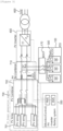
- FIG. 3 is a connection relationship diagram between each system in a DC-coupling photovoltaic-ESS connection system according to embodiments of the present invention.
- FIG. 3 shows a system configuration focusing on hardware components necessary to actually implement connection between a photovoltaic system 700 and an energy storage system 100 when the photovoltaic system 700 and the energy storage system 100 are connected with the power grid 600 through DC coupling.
- the photovoltaic system 700 includes a PV array 701 in which PV strings are connected in parallel and a PV combiner 702 which is implemented as a distribution board for connecting a plurality of positive terminals of the PV strings in the PV array into one, and connecting a plurality of negative terminals into one.
- the switch connecting the positive terminals and the switch connecting the negative terminals in the PV combiner 702 are maintained always connected except for operational needs such as failure or inspection.
- Each PV string may include a plurality of PV panels connected in series to form a DC bus voltage of 1000V to 1500V.
- the photovoltaic system 700 generally forms a maximum voltage of 1000V to 1500Vdc and, for a large-capacity power generation system, it is possible to reduce installation costs such as cable price reduction by increasing an output voltage while using a low current capacity compared to a same power.
- the energy storage system 100 may be configured using various energy sources as an energy storage device, but in this embodiment, a secondary battery will be described as an energy source.
- a voltage of 1000V to 1500Vdc may be formed by configuring a battery rack by connecting a plurality of battery packs in series as described above with reference to FIG. 2 .
- the solar inverter may adjust the voltage of the DC bus by performing Maximum Power Point Tracking (MPPT) control according to a power generation state of the PV.
- MPPT Maximum Power Point Tracking
- the PV system is directly connected to the battery, it is difficult to adjust the DC bus voltage. Therefore, in the DC coupling system, a separate DC/DC converter is required in the ESS (i.e., a battery system).
- Maximum Power Point Tracking (MPPT) control is a form of control that allows maximum power to be obtained by appropriately adjusting a load according to external circumstances.
- a point at which maximum power is delivered is referred to as a maximum power operating point, and the maximum power operating point may be changed according to external conditions such as solar radiation and temperatures.
- FIGS. 2 and 3 a system in which a separate DC/DC converter is applied to each battery rack is exemplified, but the present invention may also applied to a system in which a central DC/DC converter is commonly connected to a plurality of battery racks.
- the DC/DC converters for respective battery racks has an advantage of allowing individual control according to a state of each battery rack whereas the system may be complicated and the central DC/DC converter has an advantage of a simple system configuration with requirement of fewer facility.
- the PV re-combiner 710 may serve as a switchboard for physically connecting the photovoltaic system and the energy storage system.
- the PV re-combiner 710 may include a remote disconnector, a PV inverter connection terminal, and an ESS connection terminal.
- the PV re-combiner may be understood as the same component as a PV connection apparatus or a PV connection device mentioned elsewhere in this specification.
- the PV re-combiner may separate the photovoltaic system from the DC bus by using a remote disconnector for example, during night time, to prevent a decrease in power generation efficiency. Even when the photovoltaic system is not generating power, a voltage may be applied to the DC bus connected to the ESS and, when a voltage is applied to the photovoltaic system during no-power generation of the photovoltaic system, a reverse current which has an opposite direction to a power generation direction may be generated. This may cause a decrease in power generation efficiency as if continuous discharge occurring in the battery system. Therefore, according to embodiments of the present invention, the PV system is separated from the DC bus at night time when the photovoltaic system does not generate power, thereby increasing ESS power generation efficiency.
- the remote disconnector may be implemented as a motorized disconnector.
- the PV re-combiner 710 may further include a fuse, a ground fault detection interrupter (GFDI) for preventing a ground fault, a current monitor for checking an amount of PV power generation, and an IO (Input Output) port.
- GFDI ground fault detection interrupter
- IO Input Output
- a GFDI is a device connected between a power line and the ground, and may cut off a current when the current flowing from the power line to the ground exceeds a certain reference value.
- an IMD Insulation Monitoring Device
- RCM Residential Current Monitoring
- An IMD is a device that measures and monitors an insulation resistance value between a positive terminal and the ground, and between a negative terminal and the ground.
- the RCM is a device that detects leakage current by monitoring whether a sum of currents flowing through each of the positive power line and the negative power line is zero.
- PV re-combiner Another role of the PV re-combiner is to prevent inflow of fault current. Since the photovoltaic system and the energy storage system are connected without any separating device, fault current may flow in the event of a ground fault. Therefore, in the present invention, it is possible to prevent the inflow of fault current and achieve optimization of ground fault monitoring by monitoring a ground fault of the photovoltaic system during power generation and by separating the photovoltaic system from other systems during non-power generation through the PV re-combiner.
- a subject of controlling operations of the PV re-combiner (710), the PV inverter (400), and the energy storage system (100) may a power management control device or energy management device (PMS/EMS) (300).
- PMS/EMS energy management device
- the entire energy management system may operate in a first operation mode.
- the PV inverter may supply power according to the MPPT algorithm. Since it is a period in which photovoltaic power generation is performed, the ESS 100 may be in a charging state.
- the ESS may operate in a constant power (CP) mode.
- the GFDI included in the PV re-combiner 710 may constantly monitor a ground fault in the PV system.
- the entire energy management system may operate in a second operation mode.
- the ESS 100 may discharge in a constant voltage (CV) mode and the PV inverter may supply power in a constant power (CP) mode.
- the GFDI may monitor the PV system for ground faults.
- an IMD disposed on the DC bus may be activated to monitor insulation state of the DC bus (ESS and PV inverter) at night.
- the DC/DC converter 500 may be connected to the PV re-combiner 710 through a Battery DC Panel (BDCP) 170.
- BDCP Battery DC Panel
- EMS is presented as an entity that manages the entire system in conjunction with the PMS, but the energy management system described in this specification may refer to a system concept which is connected with an energy storage system (ESS) and a photovoltaic (PV) system and include a power management control device (PMS) that checks whether the photovoltaic (PV) system is able to generate power based on external conditions and a PV re-combiner configured to disconnect the photovoltaic system from a DC bus which is connected to DC power lines of the energy storage system and an inverter (PCS) according to a control command from the power management control device, and may further refer to a system for managing energy, the system including all components shown in FIG. 3 .
- PMS power management control device
- PCS inverter
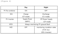
- FIG. 4 is a table showing a method of operating a DC-coupling photovoltaic-ESS connection system based on external conditions according to embodiments of the present invention.
- the operation method is described by distinguishing temporal conditions, that is, day and night, as external conditions.
- the external conditions may include not only temporal conditions, but also weather conditions.
- the operation method according to the night of the present embodiment can be applied even in conditions in which sunlight cannot be expected for a long time, such as, during a rainy season.
- the PV re-combiner 710 maintains a connection state between the PV system and the DC bus to be ON.
- the PV inverter supplies power according to MPPT control. Since it is a period in which photovoltaic power generation is performed, the ESS 100 may be charging. Here, the ESS may operate in a constant power (CP) mode.
- the GFDI included in the PV re-combiner 710 may constantly monitor a ground fault of the PV system.
- the PV re-combiner 710 may disconnect the PV system from the DC bus.
- the ESS 100 may discharge in a constant voltage (CV) mode and the PV inverter may supply power in a constant power (CP) mode.
- the GFDI may monitor the PV system for ground faults.
- the system according to the present invention may further include an insulation monitoring Device (IMD), which is disposed on the DC bus may be activated to monitor insulation state of the DC bus (ESS and PV inverter) at night.
- IMD insulation monitoring Device
- the IMD may operate as off during the daytime.
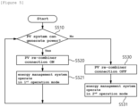
- FIG. 5 is an operational flowchart of a control method of an energy management system according to embodiments of the present invention.
- the control method of the energy management system according to the present invention may be performed by a control device that interworks with an energy storage system (ESS) and a photovoltaic (PV) system associated therewith.
- the control device may determine whether the photovoltaic (PV) system can generate power based on external conditions (S510).
- the external conditions may include one or more of time conditions and weather conditions related to whether photovoltaic power generation is possible.
- the connection between the photovoltaic (PV) system and the DC bus may be maintained (S520) or disconnected (S530) using a PV re-combiner which is located between the photovoltaic (PV) system and the DC bus that is connected to DC power lines of an energy storage system (ESS) and an inverter (PCS) .
- PV photovoltaic
- ESS energy storage system
- PCS inverter
- the PV re-combiner 710 maintains the connection state between the PV system and the DC bus to be ON. In contrast, during the night when photovoltaic generation is impossible, the PV system and the DC bus are disconnected by the PV re-combiner.
- the entire energy management system may operate in a first operation mode (S521).
- the PV inverter supplies power according to the MPPT algorithm. Since it is a period in which photovoltaic power generation is performed, the ESS 100 may be in a charging state. Here, the ESS may operate in a constant power (CP) mode.
- CP constant power
- a GFDI included in the PV re-combiner 710 may constantly monitor a ground fault of the PV system.
- the entire energy management system may operate in a second operation mode (S531).
- the ESS 100 may discharge using a constant voltage (CV) mode and the PV inverter may supply power using a constant power (CP) mode.
- the GFDI may also monitor the PV system for ground faults.
- an IMD disposed on the DC bus may be activated to monitor insulation state of the DC bus (ESS and PV inverter) at nighttime.
- a ground fault of the PV system can be monitored during photovoltaic power generation through the PV re-combiner and the PV system is separated from the ESS during non-power generation, thereby optimizing fault current inflow and ground fault monitoring.
- the operations of the method according to the embodiments of the present invention may be implemented as a computer-readable program or code on a computer-readable recording medium.
- the computer-readable recording medium includes all types of recording devices in which data readable by a computer system is stored.
- the computer-readable recording medium may be distributed in a network-connected computer system to store and execute computer-readable programs or codes in a distributed manner.
- a block or apparatus corresponds to a method step or feature of a method step.
- aspects described in the context of a method may also represent a feature of a corresponding block or item or a corresponding apparatus.
- Some or all of the method steps may be performed by (or using) a hardware device, such as, for example, a microprocessor, a programmable computer, or an electronic circuit. In some embodiments, one or more of the most important method steps may be performed by such an apparatus.
Landscapes
- Engineering & Computer Science (AREA)
- Power Engineering (AREA)
- Charge And Discharge Circuits For Batteries Or The Like (AREA)
- Supply And Distribution Of Alternating Current (AREA)
Applications Claiming Priority (3)
| Application Number | Priority Date | Filing Date | Title |
|---|---|---|---|
| KR20220011267 | 2022-01-26 | ||
| KR1020230003808A KR20230115237A (ko) | 2022-01-26 | 2023-01-11 | Pv-ess 직접 연계형 에너지관리 시스템 및 태양광발전 시스템 연동 장치 |
| PCT/KR2023/000655 WO2023146176A1 (ko) | 2022-01-26 | 2023-01-13 | Pv-ess 직접 연계형 에너지관리 시스템 및 태양광발전 시스템 연동 장치 |
Publications (2)
| Publication Number | Publication Date |
|---|---|
| EP4329131A1 true EP4329131A1 (de) | 2024-02-28 |
| EP4329131A4 EP4329131A4 (de) | 2025-01-08 |
Family
ID=87472283
Family Applications (1)
| Application Number | Title | Priority Date | Filing Date |
|---|---|---|---|
| EP23747218.8A Pending EP4329131A4 (de) | 2022-01-26 | 2023-01-13 | Energieverwaltungssystem mit direkter pv-ess-verbindung und interworking-vorrichtung für fotovoltaisches stromerzeugungssystem |
Country Status (4)
| Country | Link |
|---|---|
| US (1) | US12463432B2 (de) |
| EP (1) | EP4329131A4 (de) |
| JP (1) | JP7758378B2 (de) |
| WO (1) | WO2023146176A1 (de) |
Families Citing this family (1)
| Publication number | Priority date | Publication date | Assignee | Title |
|---|---|---|---|---|
| DE102023126151A1 (de) * | 2023-09-26 | 2025-03-27 | Sma Solar Technology Ag | Pv-energieerzeugungsanlage mit zentralwechselrichter |
Family Cites Families (31)
| Publication number | Priority date | Publication date | Assignee | Title |
|---|---|---|---|---|
| JP2003158282A (ja) | 2001-08-30 | 2003-05-30 | Canon Inc | 太陽光発電システム |
| KR101116430B1 (ko) | 2010-06-07 | 2012-02-27 | 삼성에스디아이 주식회사 | 에너지 저장 시스템 |
| WO2013005804A1 (ja) * | 2011-07-07 | 2013-01-10 | 三洋電機株式会社 | スイッチング装置 |
| KR101764651B1 (ko) | 2011-11-10 | 2017-08-03 | 엘지전자 주식회사 | 태양광 발전 장치 연계형 전력공급장치 및 이의 제어 방법 |
| KR101550227B1 (ko) | 2012-11-28 | 2015-09-11 | 에스케이 주식회사 | 외기 온도를 이용한 최대 전력점 추종을 제어하는 계통 연계형 전력 저장 시스템 및 방법 |
| KR101533337B1 (ko) | 2013-05-06 | 2015-07-06 | 주식회사 테크톤 | 듀얼 인버터를 구비한 독립형 태양광발전 시스템 및 이로 구성되는 소규모 전력망의 전력을 제어하는 중앙제어시스템 |
| JP6140527B2 (ja) | 2013-05-24 | 2017-05-31 | ケージーエス株式会社 | 太陽光発電向けストリングモニタシステム |
| CN104836321B (zh) * | 2015-05-08 | 2017-11-28 | 南京熊猫电子股份有限公司 | 智能型光伏储能系统电源及其控制方法 |
| US10263430B2 (en) | 2015-08-14 | 2019-04-16 | Solarcity Corporation | Multi-phase inverter power control systems in an energy generation system |
| KR20170038640A (ko) | 2015-09-30 | 2017-04-07 | 주식회사 엠씨티 | 에너지저장장치 전력 연동제어시스템 및 제어방법 |
| DE102016209799A1 (de) * | 2016-06-03 | 2017-12-07 | Bender Gmbh & Co. Kg | Schaltungsanordnungen zur Reduzierung der potenzialinduzierten Degradation bei Fotovoltaik-Modulen |
| JP6745460B2 (ja) | 2016-07-29 | 2020-08-26 | パナソニックIpマネジメント株式会社 | 電力供給システム |
| KR101849664B1 (ko) | 2017-01-05 | 2018-04-17 | (주)지필로스 | 태양광 발전 장치 연계형 전력공급장치 및 그 동작방법 |
| KR20180090673A (ko) | 2017-02-03 | 2018-08-13 | 롯데케미칼 주식회사 | 하이브리드 에너지 저장 시스템 |
| KR101929249B1 (ko) | 2017-04-27 | 2018-12-14 | 세방전지(주) | 태양광 연계형 에너지 저장 시스템 |
| KR102261258B1 (ko) | 2017-08-14 | 2021-06-07 | 다이너파워 컴퍼니 엘엘씨 | 양방향 저장 및 재생 가능한 전력 변환기를 위한 방법 및 장치 |
| JP6932607B2 (ja) | 2017-10-11 | 2021-09-08 | Ntn株式会社 | 直流給電システム |
| CN108039852A (zh) * | 2017-12-06 | 2018-05-15 | 武汉地质资源环境工业技术研究院有限公司 | 一种氢能和太阳能互补的热电联供系统及其工作方法 |
| JP2019122182A (ja) | 2018-01-10 | 2019-07-22 | 三菱電機株式会社 | 電力変換システム |
| US10951040B2 (en) * | 2018-04-27 | 2021-03-16 | Nextracker Inc. | DC/DC converter for distributed storage and solar systems |
| JP7072989B2 (ja) | 2018-06-07 | 2022-05-23 | ニチコン株式会社 | 蓄電システム |
| JP6969630B2 (ja) | 2018-07-10 | 2021-11-24 | 住友電気工業株式会社 | 電源装置、分配システム、及び電力変換装置 |
| KR102167279B1 (ko) | 2018-11-27 | 2020-10-19 | 원광전력주식회사 | 태양광 발전 시스템의 출력 안정화를 위한 에너지 저장 시스템의 제어 방법 |
| KR102920218B1 (ko) | 2018-12-06 | 2026-01-30 | 주식회사 엘지에너지솔루션 | 에너지저장시스템(ess)의 전력 운영 시스템 및 방법 |
| CN109768570A (zh) * | 2018-12-27 | 2019-05-17 | 陕西科技大学 | 一种具有apf功能的光储并网发电系统及其控制方法 |
| KR20200083794A (ko) | 2018-12-28 | 2020-07-09 | 선광엘티아이(주) | 에너지 저장 시스템 및 전력 변환 시스템 간 지락 검출 방법 |
| KR102110140B1 (ko) | 2018-12-28 | 2020-05-13 | 군산대학교산학협력단 | 다중 배터리 기반의 독립형 신재생에너지 시스템 |
| KR20220011267A (ko) | 2020-07-21 | 2022-01-28 | 변무현 | 얼음찜질기 |
| CN215185883U (zh) * | 2021-04-06 | 2021-12-14 | 阳光电源股份有限公司 | 一种光储系统 |
| KR102629168B1 (ko) | 2021-06-30 | 2024-01-29 | 신현의 | 골프 스윙 연습용 경사 조절 발판 |
| CN113794263B (zh) * | 2021-09-06 | 2025-02-25 | 珠海格力电器股份有限公司 | 光伏供电电路、控制方法、电器设备及电能调度方法 |
-
2023
- 2023-01-13 EP EP23747218.8A patent/EP4329131A4/de active Pending
- 2023-01-13 US US18/564,905 patent/US12463432B2/en active Active
- 2023-01-13 JP JP2023577229A patent/JP7758378B2/ja active Active
- 2023-01-13 WO PCT/KR2023/000655 patent/WO2023146176A1/ko not_active Ceased
Also Published As
| Publication number | Publication date |
|---|---|
| JP2024521480A (ja) | 2024-05-31 |
| US20240275171A1 (en) | 2024-08-15 |
| US12463432B2 (en) | 2025-11-04 |
| JP7758378B2 (ja) | 2025-10-22 |
| EP4329131A4 (de) | 2025-01-08 |
| WO2023146176A1 (ko) | 2023-08-03 |
Similar Documents
| Publication | Publication Date | Title |
|---|---|---|
| US8552590B2 (en) | Energy management system and grid-connected energy storage system including the energy management system | |
| US8766590B2 (en) | Energy storage system of apartment building, integrated power management system, and method of controlling the system | |
| KR101084215B1 (ko) | 에너지 저장 시스템 및 이의 제어 방법 | |
| CN102097821B (zh) | 并网能量存储系统以及控制并网能量存储系统的方法 | |
| US7800247B2 (en) | Storage system that maximizes the utilization of renewable energy | |
| TWI470893B (zh) | 電能供應系統 | |
| US10298006B2 (en) | Energy storage system and method of driving the same | |
| EP2346138A2 (de) | Energiespeichervorrichtung | |
| US9899871B2 (en) | Islanded operating system | |
| US20130088900A1 (en) | Energy storage system and controlling method of the same | |
| US20190237980A1 (en) | Battery system | |
| US12463430B2 (en) | Energy storage system and method for controlling grounding structure of energy storage system | |
| KR20130105616A (ko) | 에너지 저장 시스템 및 이의 제어방법 | |
| EP4329131A1 (de) | Energieverwaltungssystem mit direkter pv-ess-verbindung und interworking-vorrichtung für fotovoltaisches stromerzeugungssystem | |
| US20250330038A1 (en) | Energy storage system, and device for controlling ground structure of energy storage system | |
| KR20230115237A (ko) | Pv-ess 직접 연계형 에너지관리 시스템 및 태양광발전 시스템 연동 장치 | |
| CN117413442A (zh) | Pv-ess直连式能量管理系统与光伏发电系统互通设备 | |
| CN119519538A (zh) | 离网光储系统、控制方法、充放电方法及电路 | |
| KR20150111639A (ko) | 계통 연계형 시스템에서의 자동 스위칭 제어 장치 및 제어 방법 |
Legal Events
| Date | Code | Title | Description |
|---|---|---|---|
| STAA | Information on the status of an ep patent application or granted ep patent |
Free format text: STATUS: THE INTERNATIONAL PUBLICATION HAS BEEN MADE |
|
| PUAI | Public reference made under article 153(3) epc to a published international application that has entered the european phase |
Free format text: ORIGINAL CODE: 0009012 |
|
| STAA | Information on the status of an ep patent application or granted ep patent |
Free format text: STATUS: REQUEST FOR EXAMINATION WAS MADE |
|
| 17P | Request for examination filed |
Effective date: 20231120 |
|
| AK | Designated contracting states |
Kind code of ref document: A1 Designated state(s): AL AT BE BG CH CY CZ DE DK EE ES FI FR GB GR HR HU IE IS IT LI LT LU LV MC ME MK MT NL NO PL PT RO RS SE SI SK SM TR |
|
| A4 | Supplementary search report drawn up and despatched |
Effective date: 20241210 |
|
| RIC1 | Information provided on ipc code assigned before grant |
Ipc: H02J 7/35 20060101ALN20241204BHEP Ipc: H02S 50/00 20140101ALI20241204BHEP Ipc: H02J 1/10 20060101ALI20241204BHEP Ipc: H02J 3/38 20060101ALI20241204BHEP Ipc: H02J 3/32 20060101AFI20241204BHEP |
|
| DAV | Request for validation of the european patent (deleted) | ||
| DAX | Request for extension of the european patent (deleted) | ||
| STAA | Information on the status of an ep patent application or granted ep patent |
Free format text: STATUS: EXAMINATION IS IN PROGRESS |
|
| 17Q | First examination report despatched |
Effective date: 20250624 |