EP4329191A1 - Dispositif et système de montage de panneaux solaires sur des toits métalliques - Google Patents
Dispositif et système de montage de panneaux solaires sur des toits métalliques Download PDFInfo
- Publication number
- EP4329191A1 EP4329191A1 EP23164968.2A EP23164968A EP4329191A1 EP 4329191 A1 EP4329191 A1 EP 4329191A1 EP 23164968 A EP23164968 A EP 23164968A EP 4329191 A1 EP4329191 A1 EP 4329191A1
- Authority
- EP
- European Patent Office
- Prior art keywords
- hinge
- platform
- roof
- slot
- shaped portion
- Prior art date
- Legal status (The legal status is an assumption and is not a legal conclusion. Google has not performed a legal analysis and makes no representation as to the accuracy of the status listed.)
- Granted
Links
Images


Classifications
-
- H—ELECTRICITY
- H02—GENERATION; CONVERSION OR DISTRIBUTION OF ELECTRIC POWER
- H02S—GENERATION OF ELECTRIC POWER BY CONVERSION OF INFRARED RADIATION, VISIBLE LIGHT OR ULTRAVIOLET LIGHT, e.g. USING PHOTOVOLTAIC [PV] MODULES
- H02S20/00—Supporting structures for PV modules
- H02S20/20—Supporting structures directly fixed to an immovable object
- H02S20/22—Supporting structures directly fixed to an immovable object specially adapted for buildings
- H02S20/23—Supporting structures directly fixed to an immovable object specially adapted for buildings specially adapted for roof structures
-
- Y—GENERAL TAGGING OF NEW TECHNOLOGICAL DEVELOPMENTS; GENERAL TAGGING OF CROSS-SECTIONAL TECHNOLOGIES SPANNING OVER SEVERAL SECTIONS OF THE IPC; TECHNICAL SUBJECTS COVERED BY FORMER USPC CROSS-REFERENCE ART COLLECTIONS [XRACs] AND DIGESTS
- Y02—TECHNOLOGIES OR APPLICATIONS FOR MITIGATION OR ADAPTATION AGAINST CLIMATE CHANGE
- Y02B—CLIMATE CHANGE MITIGATION TECHNOLOGIES RELATED TO BUILDINGS, e.g. HOUSING, HOUSE APPLIANCES OR RELATED END-USER APPLICATIONS
- Y02B10/00—Integration of renewable energy sources in buildings
- Y02B10/20—Solar thermal
-
- Y—GENERAL TAGGING OF NEW TECHNOLOGICAL DEVELOPMENTS; GENERAL TAGGING OF CROSS-SECTIONAL TECHNOLOGIES SPANNING OVER SEVERAL SECTIONS OF THE IPC; TECHNICAL SUBJECTS COVERED BY FORMER USPC CROSS-REFERENCE ART COLLECTIONS [XRACs] AND DIGESTS
- Y02—TECHNOLOGIES OR APPLICATIONS FOR MITIGATION OR ADAPTATION AGAINST CLIMATE CHANGE
- Y02E—REDUCTION OF GREENHOUSE GAS [GHG] EMISSIONS, RELATED TO ENERGY GENERATION, TRANSMISSION OR DISTRIBUTION
- Y02E10/00—Energy generation through renewable energy sources
- Y02E10/40—Solar thermal energy, e.g. solar towers
- Y02E10/47—Mountings or tracking
-
- Y—GENERAL TAGGING OF NEW TECHNOLOGICAL DEVELOPMENTS; GENERAL TAGGING OF CROSS-SECTIONAL TECHNOLOGIES SPANNING OVER SEVERAL SECTIONS OF THE IPC; TECHNICAL SUBJECTS COVERED BY FORMER USPC CROSS-REFERENCE ART COLLECTIONS [XRACs] AND DIGESTS
- Y02—TECHNOLOGIES OR APPLICATIONS FOR MITIGATION OR ADAPTATION AGAINST CLIMATE CHANGE
- Y02E—REDUCTION OF GREENHOUSE GAS [GHG] EMISSIONS, RELATED TO ENERGY GENERATION, TRANSMISSION OR DISTRIBUTION
- Y02E10/00—Energy generation through renewable energy sources
- Y02E10/50—Photovoltaic [PV] energy
Definitions
- the present disclosure relates to solar panel racking systems, also known as solar panel mountings systems, as well as devices for mounting solar panels to metal roofs.
- Solar photovoltaic panels are installed on various types of residential and commercial roofs. These roofs can be found on building roof tops or can be found on shade structures such as awnings and carports. Residential and commercial roofs can be constructed from overlapping metal panels that are typically made of galvanized steel or aluminum. These panels come in a variety of profiles including flat, corrugated, or ribbed.
- Flat metal roofs are predominantly flat and can be interspersed with small ribs for added strength.
- Corrugated metal roofs typically have a rounded or wavy cross-sectional profile.
- Ribbed metal panels typically have ribs that can have sloped or straight sides and a flat top. Ribbed metal panels with straight sides and a flat top are known as box-rib because of their box-like shape. Ribbed metal panels where the ribs have sloped sides and a flat top are known as trapezoidal roof panels because of their trapezoidal shape. Often metal panel profiles can come in a combination of trapezoidal-shaped and box-shaped ribs. For example, what could be considered in the trade as a trapezoidal roof panel may actually comprise trapezoidal-shaped ribs separated by relatively flat sections of panel with box-shaped ribs added to the flat section for strength. The box-shaped ribs are narrow and low as compared with the trapezoidal ribs.
- Solar panels can be attached to the above described metal roofs through racking systems that include rails and mounting devices that secure the rails to the metal roofs.
- the inventor set out to create a solar panel racking system that can be secured to a variety of metal roof profiles including corrugated, trapezoidal, and flat roofs. He accomplished this by developing a mounting device that is hinged, and optionally adjustable in width, so that it may accommodate a variety of metal roof types and profiles.
- the racking system is secured to the mounting device.
- the mounting device is secured to the roof surface.
- the inventor simplified the hinge or pivoting mechanism of the mounting device by creating a pair of hinge bases, each with a hinge pin running lengthwise along their respective hinge base.
- Hollow arcuate-shaped hinge sleeves extend downward from a hinge platform assembly.
- the hinge sleeves at least partially surround the hinge pins and extend into slot-shaped apertures.
- the hinge sleeves are held captive around the hinge pins and within the hinge base by the slot-shaped apertures.
- the slot-shaped apertures are positioned lengthwise through the hinge bases and parallel to the hinge pins.
- the hinge bases attach the mounting device to the metal roof panels using roof mounting fasteners, such as self-drilling screws.
- the self-drilling screws extend into a corresponding gasket positioned under each of the hinge bases.
- the hinge platform assembly is used to mount solar racking brackets, such as an L-foot or L-foot adapters and other solar panel racking devices such as rails or rails in combination with an L-foot or L-foot adapter.
- the hinge platform assembly can be a single unit or can be divided into two sections to allow widthwise adjustment in order to accommodate a wider variety of metal roof profiles.
- the hinge platform assembly can include a hinge platform with a slot-shaped aperture and a hinge sub-platform with a threaded aperture. A threaded fastener can pass into the slot-shaped aperture and threadedly engage the threaded aperture.
- the slot-shaped aperture allows the hinge platform to be moved widthwise relative to the hinge sub-platform.
- the hinge pins can extend directly and rigidly upward from their respective hinge bases with the slot-shaped aperture positioned within the roof-anchoring platform of the hinge base.
- the hinge pin can extend from the end of a riser that extends upward from and lengthwise along the hinge base.
- the slot-shaped aperture could extend lengthwise through the riser.
- top,” “bottom,” “front,” “side,” “left,” and “right” are relative terms. Specific dimensions are intended to help the reader understand the scale of the disclosed material. Dimensions given are typical and the claims are not limited to the recited dimensions. Ordinals such as “first,” “second,” or “third,” are used in this Detailed Description and in the claims to differentiate between similarly-named parts and do not imply a particular order, preference, or importance. "Optional” or “optionally” is used throughout this disclosure to describe features or structures that are optional. Not using the word “optional” or “optionally” to describe a feature or structure does not imply that the feature or structure is not optional. Finally, the word “or” is used in the ordinary sense to mean an “inclusive or,” unless preceded by a qualifier, such as the word “either,” that signals an “exclusive or.”
- the inventor developed a mounting device that allows solar panels to be attached to various types of metal roofs. These include metal roofs with corrugated, flat, and ribbed metal panels.
- This Detailed Description is divided into a System Overview, General Concepts, Examples, and Conclusion.
- the System Overview which is illustrated by FIGS. 1-4 , discusses the mounting device in relationship to a solar panel assembly.
- the General Concepts which is illustrated in FIGS. 5-13 , discuss the structure and function of the mounting device. Examples, which are illustrated in FIGS. 14-18 , discuss various roof structures that the mounting device can attach to.
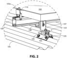
- FIG. 1 illustrates a simplified version of a solar panel assembly 100 that includes several instances of the mounting device 101.
- the instances of the mounting device 101 are part of a solar panel racking system 102.
- Solar panel racking system 102 secures solar panel 103 to metal roof 104.
- the solar panel assembly 100 is simplified for illustration.
- Residential and commercial solar panel systems typically include many more solar panels. For example, a 20-kW residential array using 480 W solar panels would require forty-two solar panels. A 1000 kW (1 MW) commercial system using 480 W solar panels would require over 2000 solar panels and could include as many as 2000 instances of the mounting device 101.
- the mounting device 101 is fastened to the metal roof 104 using several instances of a roof mounting fastener 105.
- the mounting device 101 can optionally include an L-foot 107.
- the L-foot 107 is fastened to the L-foot adapter 108, that clamps over a portion of the outside of a rail 109 by pressure.
- An over-the-panel clamp 110 in the form of an end clamp, clamps the top of the frame 103a of the solar panel 103 to the rail 109.
- the mounting device 101 is not limited to the racking system 102 shown in FIG. 1 .
- an L-foot could be fastened directly to a rail that includes a slotted side.
- an under-the-panel clamp could clamp the return flange 103b (i.e. inner frame lip) of frame 103a of the solar panel 103 to the rail 109.
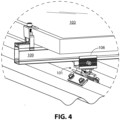
- the L-foot adapter 108 could attach directly to the mounting device 101 without the need for the L-foot.
- the mounting device 101 is illustrated as including a first hinge base 111, a second hinge base 112, a hinge platform 113, a hinge sub-platform 114, and optionally, the L-foot 107.
- the hinge platform 113 and hinge sub-platform 114 are secured together by a threaded fastener 115 to form a hinge platform assembly 117.
- the threaded fastener body 115a passes through slot-shaped aperture 113a in the hinge platform 113 and threadedly engages a threaded aperture 114a in hinge sub-platform 114. With the threaded fastener 115 tightened, the hinge platform 113 and the hinge sub-platform 114 form a rigid assembly.
- the L-foot 107 or alternatively another solar racking bracket, such as the L-foot adapter 108, as described for FIG. 4 , can be attached to the hinge platform assembly 117 by the threaded fastener 115.
- the L-foot 107 can be secured to the hinge platform assembly 117 by passing the threaded fastener body 115a through a slot-shaped aperture 107a on the L-foot base 107b, through the slot-shaped aperture 113a, and then threadedly engaging the threaded aperture 114a.
- the L-foot 107 also includes an L-foot riser 107c that extends upward from the L-foot base 107b.
- the L-foot riser 107c is illustrated with a slot-shaped opening 107d.
- the slot-shaped opening 107d of FIG. 5 allows a fastener, such as threaded fastener 106, to engage the L-foot adapter 108, and move the rail 109 up or down relative to the L-foot base 107b.
- the L-foot riser 107c can include a keeper 107e extending outward from the L-foot riser 107c in the direction of the L-foot base 107b to prevent a partially-tightened fastener from exiting the top of the slot-shaped opening 107d.
- the first hinge base 111 includes roof-anchoring platform 111a, riser 111b extending upward from the roof-anchoring platform 111a, and hinge pin 111c extending lengthwise along the end of riser 111b.
- the end of riser 111b is distal to the roof-anchoring platform 111a.
- the hinge pin 111c is rigidly attached to the end of the riser 111b forming a rigid structure with roof-anchoring platform 111a.
- the second hinge base 112 includes roof-anchoring platform 112a, riser 112b extending upward from the roof-anchoring platform 112a, and hinge pin 112c extending lengthwise along the end of riser 112b.
- the end of riser 112b is distal to the roof-anchoring platform 112a.
- the hinge pin 112c is rigidly attached to the end of the riser 112b forming a rigid structure with the roof-anchoring platform 112a.
- the roof-anchoring platform 111a and roof-anchoring platform 112a include cavity 111d and cavity 112d, respectively. Cavity 111d extends below the roof-anchoring platform bottom surface 111e and between a first sidewall 111f and a second sidewall 111g. The first sidewall 111f and second sidewall 111g project downward from the roof-anchoring platform bottom surface 111e.
- Cavity 112d extends below the roof-anchoring platform bottom surface 112e and between a first sidewall 112f and a second sidewall 112g. First sidewall 112f and second sidewall 112g project downward from the roof-anchoring platform bottom surface 112e. Cavity 111d and cavity 112d receive gasket 118 and gasket 119, respectively. Gasket 118 and gasket 119 can be held in their respective cavities by pressure or can be secured by an adhesive or bonding agent. For example, gasket 118 can have a pre-applied adhesive strip that secures it to roof-anchoring platform bottom surface 111e. Alternatively, adhesive could be applied to either the roof-anchoring platform bottom surface 111e or the gasket top surface 118a.
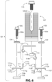
- FIGS. 5 and 6 show various instances of roof mounting fasteners, roof mounting fastener 105 with threaded fastener bodies 105a.
- the threaded fastener bodies 105a pass through a corresponding instance of a sealing washer 120, then into corresponding apertures, aperture 111h, aperture 111i, aperture 112h, and aperture 112i, and finally into corresponding gaskets, gasket 118, and gasket 119.
- the sealing washer 120 is also illustrated in FIG. 6 .
- Roof mounting fastener 105 is typically a self-taping or self-drilling screw.
- the sealing washer is typically a conical metal washer with a gasket such as polychloroprene (neoprene) or ethylene propylene diene monomer rubber (EPDM).
- first hinge base 111 and the second hinge base 112 pivotally engage the hinge platform assembly 117.
- First hinge sleeve 113b wraps around the hinge pin 111c through slot-shaped aperture 111j.
- the second hinge sleeve 114b wraps around the hinge pin 112c through slot-shaped aperture 112j.
- Slot-shaped aperture 111j is hidden from view in FIGS. 6 and 7 .
- Slot-shaped aperture 112j is hidden from view in FIGS. 6 and 9 .
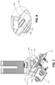
- FIG. 8 illustrates a portion of FIG. 7 , showing the interaction between the hinge pin 112c, the second hinge sleeve 114b, and the slot-shaped aperture 112j.
- FIG. 10 illustrates a portion of FIG. 9 , showing the interaction between the hinge pin 111c, first hinge sleeve 113b, and the slot-shaped aperture 111j.
- the hinge sleeve includes a hollow interior.
- the inside surface of the first hinge sleeve 113b includes an upper arcuate-shaped portion 113c, a planar portion 113d (i.e. substantially flat portion), and a lower arcuate-shaped portion 113e.
- the upper arcuate-shaped portion 113c pivotally engages the hinge pin 111c.
- the planar portion 113d rotationally stops the first hinge base 111 by engaging the riser 111b.
- FIG. 11 illustrates portions of the riser 111b, hinge pin 111c, first hinge sleeve 113b, upper arcuate-shaped portion 113c, and lower arcuate-shaped portion 113e.
- the planar portion 113d is angled to limit the outward rotation of the roof-anchoring platform 111a by acting as a rotational stop for the planar portion 113d. As illustrated, the outward rotation of the roof-anchoring platform 111a is limited to 0 degrees (i.e. horizontal). The angle of the planar portion 113d or the angle of the riser 111b can be changed to set other outward rotation stop angles.
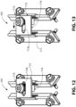
- FIGS. 12 and 13 illustrate how the width of the mounting device 101 can adjusted.
- the L-foot is removed from the figures to help illustrate width adjustment.
- a portion of the threaded fastener 115 passes through the slot-shaped aperture 113a of the hinge platform 113 and threadedly engages the hinge sub-platform 114. With the threaded fastener 115, partially tightened, the hinge sub-platform 114 in combination with the threaded fastener 115 are free to move along the slot-shaped aperture 113a.
- the threaded fastener 115 is positioned at approximately the mid-point between either end of the slot. This places the hinge platform 113 and hinge sub-platform 114 at approximately the mid-point of the width adjustment range.
- the threaded fastener 115 is positioned at approximately the end of the slot distal to the first hinge base 111. This places the hinge platform 113 and hinge sub-platform 114 at maximum width.
- FIGS. 14-18 illustrate a non-limiting sampling of what is possible, using mounting device 101.
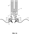
- FIG. 14 illustrates the mounting device 101 being secured to a corrugated roof 122.
- the first hinge base 111 and the second hinge base 112 are angled at approximately 42-degrees with respect to the horizon.
- the hinge platform 113 and hinge sub-platform 114 are adjusted to approximately mid-width.
- the first hinge base 111 and the second hinge base 112 would be pivoted to a shallower angle with respect to the horizon.
- hinge platform 113 and hinge sub-platform 114 would be adjusted to a wider width to accommodate the wider corrugations.
- the mounting device 101 is secured to the corrugated roof 122 by instances of the roof mounting fastener 105 passing into the corrugated roof 122 through first hinge base 111 and second hinge base 112. Instances of the roof mounting fastener 105 pass into sealing washer 120, first hinge base 111, and gasket 118. Instances of the roof mounting fastener 105 pass into sealing washer 120, second hinge base 112 and gasket 119.
- FIG. 15 illustrates the mounting device 101 secured to a substantially flat metal roof 123.
- the mounting device is shown positioned on either side of a small support rib 124.
- First hinge base 111 and second hinge base 112 are rotated so the roof-anchoring platform 111a and roof-anchoring platform 112a are horizonal.
- the mounting device 101 is secured to the substantially flat metal roof 123 by instances of roof mounting fastener 105 in combination corresponding instances of a sealing washer 120 and corresponding gaskets, gasket 118, and gasket 119.
- the instances of roof mounting fastener 105 can also be secured to decking or sheathing 125 for additional pullup strength.
- the sheathing 125 is shown as plywood.
- the mounting device 101 can also be attached to other sheathing materials, for example, plank decking, or oriented strand board (OSB).
- OSB oriented strand board
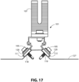
- FIGS. 16-18 illustrate the mounting device 101 secured to trapezoidal roofs of various widths and heights.
- the mounting device is adjusted to mid-width and with first hinge base 111 and second hinge base 112 adjusted to approximately a 45-degree angle with respect to the horizon to accommodate trapezoidal metal roof 126.
- the mounting device is adjusted to maximum width and with first hinge base 111 and second hinge base 112 adjusted to approximately a 45-degree angle with respect to the horizon to accommodate trapezoidal metal roof 127.
- the mounting device is adjusted to maximum width.
- First hinge base 111 is adjusted to approximately a 45-degree angle with respect to the horizon and second hinge base 112 is adjusted to approximately a 0-degrees angle with respect to the horizon to accommodate trapezoidal metal roof 128.
- the mounting device 101 is secured to the respective trapezoidal roof by instances of roof mounting fastener 105 in combination with corresponding instances of sealing washer 120 and corresponding gaskets, gasket 118 and gasket 119.
- any solar racking bracket can be used in place of the L-foot 107.
- the L-foot adapter 108 of FIG. 4 could be mounted directly to the mounting device 101 of FIGS. 14-18 if height adjustment is not required.
- the description is not exhaustive and not exclusive. Examples of components and configurations are meant to aid the reader in understanding the described general principles. The following are examples of how different components, structures, and features can be varied while still adhering to the general principles.
- the slot-shaped opening 107d can streamline assembly by providing an open end for fasteners pre-attached to racking assemblies to slide into.
- a slot-shaped opening is not required or desirable and the L-foot 107 is not limited to having a slot-shaped opening. For example, it could have a round aperture or a closed slotted aperture.
- threaded fastener 115 is illustrated as a socket head screw (or socket head bolt) with an internal hexagonal (“hex") socket.
- the threaded fastener 115 is not limited to this. It can be any threaded fastener suitable for rigidly holding together the hinge platform 113 to the hinge sub-platform 114 and optionally holding an L-foot 107 or an L-foot adapter to the hinge platform assembly 117.
- the threaded fastener can have a socket head screw with a torx, Robertson (i.e., square), or tamper-resistant sockets.
- the threaded fastener can be a hex head bolt or could be a button-head cap screw with any suitable socket or head type.
- Threaded fastener 115 can be a screw with various types of heads, for example: Philips head, combination head, slotted head, or torx head. While threaded fastener 115 is shown as flanged, it can alternatively be unflanged. Threaded fastener 115 can be paired with various washers. For example, a toothed washer, a spring washer, or a lock washer.
- Roof mounting fastener 105 discussed in FIGS. 2 , 3 , 5 , 6 , and 14-18 is illustrated as a self-drilling roofing screw with a hex head.
- the sealing washer 120 is called out as a separate component. Roof mounting fastener 105 and the sealing washer 120 are often sold as one unit.
- a hex head self-drilling roof screw with a built-in sealing washer with a neoprene seal is sold by ITW Brands under the registered trademark TEKS ® . While self-drilling or self-tapping screws are convenient, non-self-tapping or non-self-drilling screws can be used with a predrilled pilot hole.
- roof mounting fasteners typically have hex heads
- other fastener heads for example, socket heads with a hex socket or a torx socket.
- Any threaded fastener capable of securing the mounting device 101 can be used that meets local and regional regulatory requirements and can withstand the day-to-day solar array environmental installation conditions.
- the first hinge base 111 is illustrated with roof-anchoring platform 111a, riser 111b, hinge pin 111c, and slot-shaped aperture 111j, with the slot-shaped aperture 111j extending through riser 111b.
- FIG. 5 illustrates roof-anchoring platform 112a, riser 112b, hinge pin 112c, and slot-shaped aperture 112j, with slot-shaped aperture 112j extending through riser 112b. It is possible to eliminate riser 111b and have the hinge pin 111c extend directly and rigidly upward from roof-anchoring platform 111a and with the slot-shaped aperture 111j extending lengthwise through roof-anchoring platform 111a.
- hinge pin 112c could extend directly and rigidly upward from roof-anchoring platform 112a with the slot-shaped aperture 112j extending lengthwise through roof-anchoring platform 112a.
- First hinge sleeve 113b would surround hinge pin 111c and extend into slot-shaped aperture 111j, as previously described.
- Second hinge sleeve 114b would surround hinge pin 112c and extend into slot-shaped aperture 112j, also as previously described.
- First sidewall 111f, second sidewall 111g, first sidewall 112f, and second sidewall 112g could be lengthened to allow the curvature of the first hinge sleeve 113b and second hinge sleeve 114b to clear the metal roof surface.
- the hinge platform 113 and hinge sub-platform 114 are not limited to the shapes and proportions illustrated.
- the hinge platform top 113f and slot-shaped aperture 113a can be extended to allow the mounting device 101 to accommodate a greater range of metal roof profiles.
- the hinge platform riser 113g can be extended or shortened in proportion to the hinge platform top 113f to create greater or less vertical clearance.
- the angle between the hinge platform top 113f and hinge platform riser 113g is illustrated as approximately a 90-degree angle.
- the angle between the hinge platform top 113f and hinge platform riser 113g is not limited to a 90-degree angle.
- the hinge platform riser 113g could be extended and the angle between the hinge platform top 113f and hinge platform riser 113g could be changed to an obtuse angle to accommodate a greater range of trapezoidal roof profiles. Similar modifications to width, height, or angle, as given in the various examples above would typically be applied to the hinge platform top 114f and hinge platform riser 114g to maintain symmetry.
- the hinge platform assembly 117 is shown as two sub-assemblies, hinge platform 113 and hinge sub-platform 114 to allow the hinge platform assembly to be adjusted widthwise. If widthwise adjustment is not required, the hinge platform assembly 117 could be constructed as a one-piece unit.
- the first hinge sleeve 113b and the second hinge sleeve 114b are typically aligned at the same distance from the hinge platform top 113f so that they are parallel to each other. While in most applications this is desirable, there may be applications where the first hinge sleeve 113b and the second hinge sleeve 114b could be offset. In that case, first hinge sleeve 113b and the second hinge sleeve 114b would not be aligned at the same distance from the hinge platform top 113f.
- the angle of planar portion 113d could be changed to allow either a greater or lesser range of movement of the first hinge base 111.
- the first hinge base 111 can swing from an acute angle to approximately 0-degrees (i.e., flat) with respect to the plane of roof.
- the maximum extent is limited to a 0-degree angle with respect to the plane of the roof because of the angle of the planar portion 113d.
- the angle of the planar portion 113d could be changed to allow the first hinge base 111 to pivot outward to an obtuse angle.
- FIGS. 14-18 show various metal roof profiles.
- roof decking is omitted to simply the figures.
- roof decking such as the sheathing 125 in FIG. 15
- roof joists or framing could be used without roof decking.
- the terms "roof decking" and “roof sheathing” are synonymous.
- the L-foot 107 is shown without surface ribbing.
- the L-foot adapter 108 is also shown without surface ribbing.
- the ribbing shown for the L-foot adapter 108 in FIG. 4 and for the L-foot 107 in FIGS. 5 , 6 , 7 , 9 , and 14-18 is optional.
- the purpose of the surface ribbing is to provide better grip strength between the components. If these components are made of an electrically conductive material, such as aluminum, steel, or electrically conductive plastic (i.e., plastic mixed with electrically conductive material), then the surface ribbing can help to provide an electrically conductive pathway between the components.
- the components can be extruded, which can potentially reduce manufacturing costs.
- the first hinge base 111, second hinge base 112, hinge platform 113, hinge sub-platform 114, L-foot 107, as well as the L-foot adapter 108 of FIG. 4 can be made of a metallic material, such as aluminum or steel. These can potentially be extruded, cast, stamped, or otherwise formed.
Landscapes
- Engineering & Computer Science (AREA)
- Architecture (AREA)
- Civil Engineering (AREA)
- Structural Engineering (AREA)
- Roof Covering Using Slabs Or Stiff Sheets (AREA)
Applications Claiming Priority (1)
| Application Number | Priority Date | Filing Date | Title |
|---|---|---|---|
| US17/822,784 US11848638B1 (en) | 2022-08-27 | 2022-08-27 | Device and system for mounting solar panels to metal roofs |
Publications (3)
| Publication Number | Publication Date |
|---|---|
| EP4329191A1 true EP4329191A1 (fr) | 2024-02-28 |
| EP4329191C0 EP4329191C0 (fr) | 2024-12-04 |
| EP4329191B1 EP4329191B1 (fr) | 2024-12-04 |
Family
ID=85781874
Family Applications (1)
| Application Number | Title | Priority Date | Filing Date |
|---|---|---|---|
| EP23164968.2A Active EP4329191B1 (fr) | 2022-08-27 | 2023-03-29 | Dispositif et système de montage de panneaux solaires sur des toits métalliques |
Country Status (2)
| Country | Link |
|---|---|
| US (2) | US11848638B1 (fr) |
| EP (1) | EP4329191B1 (fr) |
Cited By (1)
| Publication number | Priority date | Publication date | Assignee | Title |
|---|---|---|---|---|
| US12231081B2 (en) | 2018-03-21 | 2025-02-18 | Rmh Tech Llc | PV module mounting assembly with clamp/standoff arrangement |
Families Citing this family (18)
| Publication number | Priority date | Publication date | Assignee | Title |
|---|---|---|---|---|
| US9611652B2 (en) | 2011-02-25 | 2017-04-04 | Dustin M. M. Haddock | Mounting device for building surfaces having elongated mounting slot |
| US20130168525A1 (en) | 2011-12-29 | 2013-07-04 | Dustin M.M. Haddock | Mounting device for nail strip panels |
| US10443896B2 (en) | 2016-07-29 | 2019-10-15 | Rmh Tech Llc | Trapezoidal rib mounting bracket with flexible legs |
| US12556127B1 (en) * | 2017-09-01 | 2026-02-17 | Tamarack Solar Products, Inc. | Solar panel mounting configuration |
| WO2019074956A1 (fr) | 2017-10-09 | 2019-04-18 | Rmh Tech Llc | Ensemble de rail pourvu d'un adaptateur à montage latéral réversible pour des applications de montage direct et indirect |
| AU2019397167B2 (en) | 2018-12-14 | 2023-04-06 | Rmh Tech Llc | Mounting device for nail strip panels |
| DE112021001674T5 (de) | 2020-03-16 | 2023-06-01 | Rmh Tech Llc | Befestigungsvorrichtung für ein Metalldach |
| BR112023000401A2 (pt) | 2020-07-09 | 2023-01-31 | Rmh Tech Llc | Sistema, dispositivo e método de montagem |
| US12483185B2 (en) | 2021-09-09 | 2025-11-25 | Rmh Tech Llc | Torque actuated rail assembly |
| USD1075493S1 (en) | 2022-07-06 | 2025-05-20 | Rmh Tech Llc | Clamp for a photovoltaic module mounting assembly |
| EP4695564A2 (fr) | 2023-04-14 | 2026-02-18 | RMH Tech LLC | Dispositif de montage pour un panneau métallique |
| USD1113406S1 (en) | 2023-04-14 | 2026-02-17 | Rmh Tech Llc | Mounting device |
| JP7558536B1 (ja) * | 2023-06-19 | 2024-10-01 | サンスタック エルエルシー | 架台のベースおよび架台 |
| USD1109686S1 (en) | 2023-08-10 | 2026-01-20 | Rmh Tech Llc | Mount for a component of a photovoltaic assembly |
| CN121794483A (zh) * | 2023-08-30 | 2026-04-03 | Rmh技术有限责任公司 | 用于附接到金属面板的梯形肋的可调节安装组件 |
| WO2025170750A1 (fr) | 2024-02-06 | 2025-08-14 | Yamnik Feliks E | Système de support de panneau solaire universel |
| FR3158972B1 (fr) * | 2024-02-07 | 2026-02-13 | Mecosun | Procédé de pose de modules et système correspondant |
| US12368408B1 (en) * | 2025-03-13 | 2025-07-22 | Holdco212, LLC | Systems and methods to reduce total fatigue stresses in PV frames via custom backing plate |
Citations (4)
| Publication number | Priority date | Publication date | Assignee | Title |
|---|---|---|---|---|
| EP2413064A2 (fr) * | 2010-07-30 | 2012-02-01 | Etanco GmbH | Dispositif de fixation pour installations sur toit en tôle ondulée ou trapézoïdale ou façades en tôle ondulée ou trapézoïdale ainsi que vis de montage correspondante |
| EP2230469B1 (fr) * | 2009-03-19 | 2015-05-06 | Mounting Systems GmbH | Procédé de montage de structures fonctionnelles sur des toits |
| US10840851B2 (en) * | 2017-09-08 | 2020-11-17 | D Three Enterprises Llc | Roof mount bracket |
| US11408555B2 (en) * | 2019-03-03 | 2022-08-09 | Jason Sen Xie | Metal roof mounting brackets |
Family Cites Families (19)
| Publication number | Priority date | Publication date | Assignee | Title |
|---|---|---|---|---|
| JP4959215B2 (ja) | 2006-04-14 | 2012-06-20 | 京セラ株式会社 | 固定装置 |
| WO2010129867A1 (fr) | 2009-05-07 | 2010-11-11 | Adelwiggins Group | Dispositif et procédé de serrage à verrouillage latéral |
| JP5610431B2 (ja) | 2009-10-26 | 2014-10-22 | 株式会社ニフコ | 軸支構造、クリップ、および軸支構造の金型 |
| DE202010001238U1 (de) | 2010-01-21 | 2010-04-22 | Vm Edelstahltechnik Gmbh | Trapezdach-Befestigungsvorrichtung |
| DE202010007000U1 (de) | 2010-05-20 | 2010-09-09 | Vm Edelstahltechnik Gmbh | Trapezdach-Befestigungsvorrichtung |
| PL2447437T3 (pl) * | 2010-10-29 | 2020-05-18 | Luchtankers B.V. | System bezpieczeństwa i dach wyposażony w system bezpieczeństwa |
| DE202011108518U1 (de) | 2011-12-01 | 2013-03-04 | Schletter Gmbh | Montageset für trapezförmige Rippen eines Trapezblechs |
| DE102011119847A1 (de) | 2011-12-01 | 2013-06-06 | Schletter Gmbh | Montageset für trapezförmige Rippen eines Trapezblechs |
| DE202012005672U1 (de) | 2012-06-12 | 2012-06-26 | Donauer Solartechnik Vertriebs Gmbh | Montagevorrichtung zur Anordnung eines Photovoltaikmoduls auf einem Trapezprofil sowie eine Anordnung mit einem Photovoltaikmodul und einem Trapezprofil |
| BR112015011903A2 (pt) * | 2012-11-28 | 2017-07-11 | Imo Holding Gmbh | dispositivo de rastreamento. |
| DE202013005102U1 (de) | 2013-06-06 | 2014-09-08 | Dr. Zapfe Gmbh | Vorrichtung zum Befestigen von PV-Modulen auf Dächern mit Trapezblech |
| US20160025262A1 (en) | 2014-07-23 | 2016-01-28 | Vermont Slate & Copper Services, Inc. | Corrugated surface mounting bracket |
| DE202015102941U1 (de) | 2015-06-08 | 2015-07-31 | Franz Stangl | Vorrichtung zum Befestigen von Anbauteilen auf einem Dach mit einem Trapezblech |
| EP3469706B1 (fr) * | 2016-06-12 | 2024-09-04 | Array Technologies, Inc. | Rails de montage clipsables, supports de montage, et procédés de montage de modules solaires |
| GB2558524A (en) | 2016-07-04 | 2018-07-18 | Kingspan Holdings Irl Ltd | Mounting bracket |
| US20180091088A1 (en) * | 2016-07-08 | 2018-03-29 | Alion Energy, Inc. | Systems and methods for rotatably mounting and locking solar panels |
| US11283395B2 (en) * | 2018-03-23 | 2022-03-22 | Nextracker Inc. | Multiple actuator system for solar tracker |
| US11125356B2 (en) | 2019-06-05 | 2021-09-21 | Unirac Inc. | Conduit mount bracket |
| US11649986B2 (en) * | 2020-02-05 | 2023-05-16 | John Powers, III | Purlin construction and clip for flat panel roof structures |
-
2022
- 2022-08-27 US US17/822,784 patent/US11848638B1/en active Active
-
2023
- 2023-03-29 EP EP23164968.2A patent/EP4329191B1/fr active Active
- 2023-11-02 US US18/500,349 patent/US11979108B2/en active Active
Patent Citations (4)
| Publication number | Priority date | Publication date | Assignee | Title |
|---|---|---|---|---|
| EP2230469B1 (fr) * | 2009-03-19 | 2015-05-06 | Mounting Systems GmbH | Procédé de montage de structures fonctionnelles sur des toits |
| EP2413064A2 (fr) * | 2010-07-30 | 2012-02-01 | Etanco GmbH | Dispositif de fixation pour installations sur toit en tôle ondulée ou trapézoïdale ou façades en tôle ondulée ou trapézoïdale ainsi que vis de montage correspondante |
| US10840851B2 (en) * | 2017-09-08 | 2020-11-17 | D Three Enterprises Llc | Roof mount bracket |
| US11408555B2 (en) * | 2019-03-03 | 2022-08-09 | Jason Sen Xie | Metal roof mounting brackets |
Cited By (1)
| Publication number | Priority date | Publication date | Assignee | Title |
|---|---|---|---|---|
| US12231081B2 (en) | 2018-03-21 | 2025-02-18 | Rmh Tech Llc | PV module mounting assembly with clamp/standoff arrangement |
Also Published As
| Publication number | Publication date |
|---|---|
| US20240072719A1 (en) | 2024-02-29 |
| EP4329191C0 (fr) | 2024-12-04 |
| US11848638B1 (en) | 2023-12-19 |
| US11979108B2 (en) | 2024-05-07 |
| EP4329191B1 (fr) | 2024-12-04 |
Similar Documents
| Publication | Publication Date | Title |
|---|---|---|
| EP4329191B1 (fr) | Dispositif et système de montage de panneaux solaires sur des toits métalliques | |
| US12224702B2 (en) | Solar panel racking system and devices for the same | |
| US10797634B1 (en) | Height-adjustable rail-less solar panel mounting device for roofs | |
| US20240171115A1 (en) | Jobsite Assembled Rail-Less Solar Panel Mounting System for Roofs and Methods for the Same | |
| KR101219555B1 (ko) | 태양전지 모듈 프레임 | |
| US20050217203A1 (en) | Multi-piece attachment mounting clamp for trapezoidal rib profile panels | |
| US20170093327A1 (en) | Mounting assemblies for solar panel systems and methods for using the same | |
| EP4641035A2 (fr) | Ensemble d'ancrage et de fixation combiné | |
| US4453362A (en) | Wall support device | |
| JP7570618B2 (ja) | ケラバ包み用下地金具 | |
| JP2000248700A (ja) | 樋取付け具 | |
| JP4933803B2 (ja) | サンルームの屋根構造 | |
| US12442180B2 (en) | Expansion joint assembly | |
| JP7491539B2 (ja) | エキスパンションジョイントカバー装置 | |
| JP2525908B2 (ja) | 開口パネルの上部取付構造 | |
| JP2000008529A (ja) | 簡易構築物の屋根 | |
| US20060048461A1 (en) | Connectors for roofs | |
| CA2586301C (fr) | Support a face cachee pour dispositifs de support | |
| JPH0649724Y2 (ja) | 外壁材用留付け金具 | |
| CA2358717C (fr) | Porte d'acces montee sur cadre pivotant | |
| JPH0428350Y2 (fr) | ||
| JPH02132256A (ja) | 屋根板材取付構造 | |
| HK40038019B (en) | Combined anchor and fastener assembly | |
| JP2000054529A (ja) | 建築部材取付装置 | |
| JPH04124356A (ja) | 建築物の面構造体 |
Legal Events
| Date | Code | Title | Description |
|---|---|---|---|
| PUAI | Public reference made under article 153(3) epc to a published international application that has entered the european phase |
Free format text: ORIGINAL CODE: 0009012 |
|
| STAA | Information on the status of an ep patent application or granted ep patent |
Free format text: STATUS: THE APPLICATION HAS BEEN PUBLISHED |
|
| AK | Designated contracting states |
Kind code of ref document: A1 Designated state(s): AL AT BE BG CH CY CZ DE DK EE ES FI FR GB GR HR HU IE IS IT LI LT LU LV MC ME MK MT NL NO PL PT RO RS SE SI SK SM TR |
|
| RIC1 | Information provided on ipc code assigned before grant |
Ipc: H02S 20/30 20140101ALI20240131BHEP Ipc: H02S 20/23 20140101AFI20240131BHEP |
|
| STAA | Information on the status of an ep patent application or granted ep patent |
Free format text: STATUS: REQUEST FOR EXAMINATION WAS MADE |
|
| 17P | Request for examination filed |
Effective date: 20240307 |
|
| RBV | Designated contracting states (corrected) |
Designated state(s): AL AT BE BG CH CY CZ DE DK EE ES FI FR GB GR HR HU IE IS IT LI LT LU LV MC ME MK MT NL NO PL PT RO RS SE SI SK SM TR |
|
| GRAP | Despatch of communication of intention to grant a patent |
Free format text: ORIGINAL CODE: EPIDOSNIGR1 |
|
| STAA | Information on the status of an ep patent application or granted ep patent |
Free format text: STATUS: GRANT OF PATENT IS INTENDED |
|
| RIC1 | Information provided on ipc code assigned before grant |
Ipc: H02S 20/30 20140101ALI20240828BHEP Ipc: H02S 20/23 20140101AFI20240828BHEP |
|
| INTG | Intention to grant announced |
Effective date: 20240917 |
|
| GRAS | Grant fee paid |
Free format text: ORIGINAL CODE: EPIDOSNIGR3 |
|
| GRAA | (expected) grant |
Free format text: ORIGINAL CODE: 0009210 |
|
| STAA | Information on the status of an ep patent application or granted ep patent |
Free format text: STATUS: THE PATENT HAS BEEN GRANTED |
|
| AK | Designated contracting states |
Kind code of ref document: B1 Designated state(s): AL AT BE BG CH CY CZ DE DK EE ES FI FR GB GR HR HU IE IS IT LI LT LU LV MC ME MK MT NL NO PL PT RO RS SE SI SK SM TR |
|
| REG | Reference to a national code |
Ref country code: CH Ref legal event code: EP |
|
| REG | Reference to a national code |
Ref country code: DE Ref legal event code: R096 Ref document number: 602023001221 Country of ref document: DE |
|
| REG | Reference to a national code |
Ref country code: IE Ref legal event code: FG4D |
|
| U01 | Request for unitary effect filed |
Effective date: 20241230 |
|
| U07 | Unitary effect registered |
Designated state(s): AT BE BG DE DK EE FI FR IT LT LU LV MT NL PT RO SE SI Effective date: 20250114 |
|
| PG25 | Lapsed in a contracting state [announced via postgrant information from national office to epo] |
Ref country code: HR Free format text: LAPSE BECAUSE OF FAILURE TO SUBMIT A TRANSLATION OF THE DESCRIPTION OR TO PAY THE FEE WITHIN THE PRESCRIBED TIME-LIMIT Effective date: 20241204 |
|
| PG25 | Lapsed in a contracting state [announced via postgrant information from national office to epo] |
Ref country code: ES Free format text: LAPSE BECAUSE OF FAILURE TO SUBMIT A TRANSLATION OF THE DESCRIPTION OR TO PAY THE FEE WITHIN THE PRESCRIBED TIME-LIMIT Effective date: 20241204 |
|
| PG25 | Lapsed in a contracting state [announced via postgrant information from national office to epo] |
Ref country code: NO Free format text: LAPSE BECAUSE OF FAILURE TO SUBMIT A TRANSLATION OF THE DESCRIPTION OR TO PAY THE FEE WITHIN THE PRESCRIBED TIME-LIMIT Effective date: 20250304 |
|
| PG25 | Lapsed in a contracting state [announced via postgrant information from national office to epo] |
Ref country code: GR Free format text: LAPSE BECAUSE OF FAILURE TO SUBMIT A TRANSLATION OF THE DESCRIPTION OR TO PAY THE FEE WITHIN THE PRESCRIBED TIME-LIMIT Effective date: 20250305 |
|
| PG25 | Lapsed in a contracting state [announced via postgrant information from national office to epo] |
Ref country code: RS Free format text: LAPSE BECAUSE OF FAILURE TO SUBMIT A TRANSLATION OF THE DESCRIPTION OR TO PAY THE FEE WITHIN THE PRESCRIBED TIME-LIMIT Effective date: 20250304 |
|
| U20 | Renewal fee for the european patent with unitary effect paid |
Year of fee payment: 3 Effective date: 20250329 |
|
| PG25 | Lapsed in a contracting state [announced via postgrant information from national office to epo] |
Ref country code: SM Free format text: LAPSE BECAUSE OF FAILURE TO SUBMIT A TRANSLATION OF THE DESCRIPTION OR TO PAY THE FEE WITHIN THE PRESCRIBED TIME-LIMIT Effective date: 20241204 |
|
| PG25 | Lapsed in a contracting state [announced via postgrant information from national office to epo] |
Ref country code: PL Free format text: LAPSE BECAUSE OF FAILURE TO SUBMIT A TRANSLATION OF THE DESCRIPTION OR TO PAY THE FEE WITHIN THE PRESCRIBED TIME-LIMIT Effective date: 20241204 |
|
| PG25 | Lapsed in a contracting state [announced via postgrant information from national office to epo] |
Ref country code: IS Free format text: LAPSE BECAUSE OF FAILURE TO SUBMIT A TRANSLATION OF THE DESCRIPTION OR TO PAY THE FEE WITHIN THE PRESCRIBED TIME-LIMIT Effective date: 20250404 |
|
| PG25 | Lapsed in a contracting state [announced via postgrant information from national office to epo] |
Ref country code: SK Free format text: LAPSE BECAUSE OF FAILURE TO SUBMIT A TRANSLATION OF THE DESCRIPTION OR TO PAY THE FEE WITHIN THE PRESCRIBED TIME-LIMIT Effective date: 20241204 |
|
| PG25 | Lapsed in a contracting state [announced via postgrant information from national office to epo] |
Ref country code: CZ Free format text: LAPSE BECAUSE OF FAILURE TO SUBMIT A TRANSLATION OF THE DESCRIPTION OR TO PAY THE FEE WITHIN THE PRESCRIBED TIME-LIMIT Effective date: 20241204 |
|
| PLBE | No opposition filed within time limit |
Free format text: ORIGINAL CODE: 0009261 |
|
| STAA | Information on the status of an ep patent application or granted ep patent |
Free format text: STATUS: NO OPPOSITION FILED WITHIN TIME LIMIT |
|
| PG25 | Lapsed in a contracting state [announced via postgrant information from national office to epo] |
Ref country code: MC Free format text: LAPSE BECAUSE OF FAILURE TO SUBMIT A TRANSLATION OF THE DESCRIPTION OR TO PAY THE FEE WITHIN THE PRESCRIBED TIME-LIMIT Effective date: 20241204 |
|
| 26N | No opposition filed |
Effective date: 20250905 |
|
| PG25 | Lapsed in a contracting state [announced via postgrant information from national office to epo] |
Ref country code: IE Free format text: LAPSE BECAUSE OF NON-PAYMENT OF DUE FEES Effective date: 20250329 |
|
| U20 | Renewal fee for the european patent with unitary effect paid |
Year of fee payment: 4 Effective date: 20260219 |