EP4329247A1 - Émetteur-récepteur de réseau de zone de contrôleur et procédé pour l'émetteur-récepteur - Google Patents
Émetteur-récepteur de réseau de zone de contrôleur et procédé pour l'émetteur-récepteur Download PDFInfo
- Publication number
- EP4329247A1 EP4329247A1 EP22192034.1A EP22192034A EP4329247A1 EP 4329247 A1 EP4329247 A1 EP 4329247A1 EP 22192034 A EP22192034 A EP 22192034A EP 4329247 A1 EP4329247 A1 EP 4329247A1
- Authority
- EP
- European Patent Office
- Prior art keywords
- transmitter
- transceiver
- current
- signal
- interface
- Prior art date
- Legal status (The legal status is an assumption and is not a legal conclusion. Google has not performed a legal analysis and makes no representation as to the accuracy of the status listed.)
- Granted
Links
Images





Classifications
-
- G—PHYSICS
- G06—COMPUTING OR CALCULATING; COUNTING
- G06F—ELECTRIC DIGITAL DATA PROCESSING
- G06F13/00—Interconnection of, or transfer of information or other signals between, memories, input/output devices or central processing units
- G06F13/38—Information transfer, e.g. on bus
- G06F13/40—Bus structure
-
- H—ELECTRICITY
- H04—ELECTRIC COMMUNICATION TECHNIQUE
- H04L—TRANSMISSION OF DIGITAL INFORMATION, e.g. TELEGRAPHIC COMMUNICATION
- H04L12/00—Data switching networks
- H04L12/28—Data switching networks characterised by path configuration, e.g. LAN [Local Area Networks] or WAN [Wide Area Networks]
- H04L12/40—Bus networks
- H04L12/40006—Architecture of a communication node
- H04L12/40032—Details regarding a bus interface enhancer
-
- H—ELECTRICITY
- H04—ELECTRIC COMMUNICATION TECHNIQUE
- H04L—TRANSMISSION OF DIGITAL INFORMATION, e.g. TELEGRAPHIC COMMUNICATION
- H04L12/00—Data switching networks
- H04L12/28—Data switching networks characterised by path configuration, e.g. LAN [Local Area Networks] or WAN [Wide Area Networks]
- H04L12/40—Bus networks
- H04L12/40006—Architecture of a communication node
-
- G—PHYSICS
- G06—COMPUTING OR CALCULATING; COUNTING
- G06F—ELECTRIC DIGITAL DATA PROCESSING
- G06F1/00—Details not covered by groups G06F3/00 - G06F13/00 and G06F21/00
- G06F1/26—Power supply means, e.g. regulation thereof
- G06F1/266—Arrangements to supply power to external peripherals either directly from the computer or under computer control, e.g. supply of power through the communication port, computer controlled power-strips
-
- H—ELECTRICITY
- H04—ELECTRIC COMMUNICATION TECHNIQUE
- H04B—TRANSMISSION
- H04B1/00—Details of transmission systems, not covered by a single one of groups H04B3/00 - H04B13/00; Details of transmission systems not characterised by the medium used for transmission
- H04B1/38—Transceivers, i.e. devices in which transmitter and receiver form a structural unit and in which at least one part is used for functions of transmitting and receiving
- H04B1/40—Circuits
-
- H—ELECTRICITY
- H04—ELECTRIC COMMUNICATION TECHNIQUE
- H04L—TRANSMISSION OF DIGITAL INFORMATION, e.g. TELEGRAPHIC COMMUNICATION
- H04L43/00—Arrangements for monitoring or testing data switching networks
- H04L43/08—Monitoring or testing based on specific metrics, e.g. QoS, energy consumption or environmental parameters
-
- H—ELECTRICITY
- H04—ELECTRIC COMMUNICATION TECHNIQUE
- H04L—TRANSMISSION OF DIGITAL INFORMATION, e.g. TELEGRAPHIC COMMUNICATION
- H04L43/00—Arrangements for monitoring or testing data switching networks
- H04L43/08—Monitoring or testing based on specific metrics, e.g. QoS, energy consumption or environmental parameters
- H04L43/0805—Monitoring or testing based on specific metrics, e.g. QoS, energy consumption or environmental parameters by checking availability
- H04L43/0817—Monitoring or testing based on specific metrics, e.g. QoS, energy consumption or environmental parameters by checking availability by checking functioning
-
- H—ELECTRICITY
- H04—ELECTRIC COMMUNICATION TECHNIQUE
- H04L—TRANSMISSION OF DIGITAL INFORMATION, e.g. TELEGRAPHIC COMMUNICATION
- H04L43/00—Arrangements for monitoring or testing data switching networks
- H04L43/08—Monitoring or testing based on specific metrics, e.g. QoS, energy consumption or environmental parameters
- H04L43/0823—Errors, e.g. transmission errors
- H04L43/0847—Transmission error
-
- H—ELECTRICITY
- H04—ELECTRIC COMMUNICATION TECHNIQUE
- H04L—TRANSMISSION OF DIGITAL INFORMATION, e.g. TELEGRAPHIC COMMUNICATION
- H04L12/00—Data switching networks
- H04L12/28—Data switching networks characterised by path configuration, e.g. LAN [Local Area Networks] or WAN [Wide Area Networks]
- H04L12/40—Bus networks
- H04L2012/40208—Bus networks characterized by the use of a particular bus standard
- H04L2012/40215—Controller Area Network CAN
-
- H—ELECTRICITY
- H04—ELECTRIC COMMUNICATION TECHNIQUE
- H04L—TRANSMISSION OF DIGITAL INFORMATION, e.g. TELEGRAPHIC COMMUNICATION
- H04L43/00—Arrangements for monitoring or testing data switching networks
- H04L43/16—Threshold monitoring
Definitions
- the present disclosure relates to a controller area network (CAN) transceiver and a method for the CAN transceiver
- a CAN bus network may include multiple bus devices, so called nodes or electronic control units (ECUs), such as an engine control module (ECM), a power train control module (PCM), airbags, antilock brakes, cruise control, electric power steering, audio systems, windows, doors, mirror adjustment, battery and recharging systems for hybrid/electric cars, and many more.
- ECUs electronice control units
- ECM engine control module
- PCM power train control module
- airbags airbags
- antilock brakes cruise control
- electric power steering audio systems
- windows, doors, mirror adjustment battery and recharging systems for hybrid/electric cars
- CAN Flexible Data-Rate or "CAN FD” which is an extension of the standardized CAN data link layer protocol and is meanwhile integrated into the ISO11898-1:2015 standard, can provide higher data rates.
- the standardized CAN data link layer protocol is being further extended to provide even higher data rates.
- a further extension, referred to as CAN XL, with a new level scheme allowing even higher data rates is in the definition phase discussed under CiA610 (CAN in Automation) and is moving towards standardization in the form of either a further update of the existing ISO11898 standards or a new standard.
- a Controller Area Network, CAN, transceiver comprising: a CAN BUS interface, a transmit data, TXD, interface, a receive data, RXD, interface, a receiver coupled to the CAN BUS interface and the RXD interface, and a transmitter coupled to the TXD interface and the CAN BUS interface, wherein the transceiver is configured to receive, via the TXD interface, from a CAN controller, a digital TXD transmit signal representing a frame comprising a plurality of bits, wherein the transmitter is configured to generate, at the CAN BUS interface, a BUS signal representing the bits of the frame in a sequence, wherein the transceiver is configured to measure an electrical current of the transmitter, referred to as a transmitter current, wherein the transceiver is configured to detect each dominant bit represented by the BUS signal based on the transmitter current, wherein the transceiver is configured to detect an error sequence of
- the transceiver comprises a first sensor unit, which is arranged and/or configured to measure a first current to supply the transmitter, wherein the first current forms at least a part of the transmitter current.
- the transceiver comprises first and second supply terminals for supplying electrical current to the transceiver, wherein the first sensor unit is coupled between the first supply terminal and the transmitter.
- the transceiver comprises a second sensor unit, which is arranged and/or configured to measure a second current to supply the transmitter, wherein the transmitter current is based on or formed by a mean value of the first and second current.
- the transceiver is configured to detect each dominant bit represented by the BUS signal based on the first and second currents.
- the transceiver comprises an evaluation unit connected to the at least one sensor unit such that a sensor signal from each sensor unit can be transmitted to the evaluation unit, wherein the evaluation unit is configured to compare the first current with a predefined first current threshold value and/or the second current with a predefined second current threshold value and wherein the evaluation unit is configured to trigger a positive detection of a dominant bit represented by the BUS signal if the result of the comparison indicates that the first current is greater than the first current threshold value and/or the second current is greater than the second current threshold value.
- the transceiver is configured to detect a first time duration of a plurality of successive dominant bits detected based on the transmitter current, wherein the evaluation unit is configured to compare the first time duration with a predefined reference time duration, and wherein the evaluation unit is configured to trigger a positive detection of the error sequence if a result of the comparison indicates that the first time duration is larger than the reference time duration.
- the evaluation unit is configured to generate a control signal representing a fault of the transmitter in response to a detected error sequence.
- the transceiver comprises at least one shutdown unit configured to at least partially deactivate the transmitter based on the control signal.
- the transceiver comprises a first shutdown unit and a second shutdown unit, wherein the two shutdown units are configured to jointly deactivate the transmitter based on the control signal.
- the evaluation unit is coupled to each shutdown unit to transmit the control signal to each of the at least one shutdown unit.
- the evaluation unit is coupled to the TXD interface to receive the TXD digital transmit signal, wherein the evaluation unit is configured to observe whether a dominant bit represented by the TXD transmit signal is also represented as a dominant bit by the BUS signal, wherein the evaluation unit is configured to trigger a positive detection of a transmission error if the result of the observation indicates that the dominant bit represented by the digital TXD transmission signal is not represented by the BUS signal.
- the evaluation unit is configured to generate the control signal in response to a positive detection of the transmission error.
- the transceiver is configured to transmit an error signal to the CAN controller via a further interface of the transceiver in response to a detected error sequence or a detected transmission error.
- a method for a Controller Area Network, CAN, transceiver comprising a CAN BUS interface, a transmit data, TXD, interface, a receive data, RXD, interface, a receiver coupled to the CAN BUS interface and RXD interface, and a transmitter coupled to the TXD interface and the CAN BUS interface, and wherein the method comprises the steps of:
- a CAN system comprising a CAN controller and a CAN transceiver according to the first aspect or one of the previous embodiments of the CAN transceiver, wherein the CAN controller is connected via respective signal connections to the TXD interface of the transceiver and to the RXD interface of the transceiver.
- a computer program comprising executable instructions which, when executed by a processing unit, cause the processing unit being configured to carry out the method of the second.
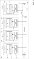
- FIG. 1 depicts a CAN network 100 that includes multiple CAN nodes 102, also referred to as "ECUs," each connected to a CAN bus 104.
- each CAN node 102 includes a microcontroller 110 having an embedded CAN protocol controller 114 and a CAN transceiver 120.
- the CAN protocol controller 114 may be referred to as a controller or CAN controller.
- the CAN transceiver 120 may be referred to as a transceiver.
- the microcontrollers 110 are typically connected to at least one device (not shown) such as a sensor, an actuator, or some other control device and are programmed to determine the meaning of received messages and to generate appropriate outgoing messages.
- the microcontrollers 110 which may also be referred to as host processors, hosts or digital signal processors (DSPs), are known in the field.
- the host supports application software that interacts with the CAN protocol controller 114.
- the CAN bus 104 carries analog differential signals and includes a first CAN signal line 124, which is also referred to as the CAN high (CANH) bus line 124, and a second CAN signal line 126, which is also referred to as the CAN low (CANL) bus line 126.
- the CAN bus 104 is known in the field.
- Figure 2 depicts an expanded view of one CAN node 102 from Figure 1 .
- the microcontroller 110 includes a host 116, which may be, for example, a software application that is stored in a memory of the microcontroller 110 and executed by processing circuits of the microcontroller 110.
- the microcontroller 110 and the CAN transceiver 120 of the CAN node 102 are connected between a first supply voltage, VCC, and as second supply voltage, which is usually ground, GND
- the CAN transceiver 120 may comprise a first supply terminal 156, that can be connected to the first supply voltage, and a second supply terminal 158, that can be connected to second supply voltage.
- the analogous terminals may be provided by the microcontroller 110 or may be even combined with the respective terminals of the microcontroller 110.
- data communicated from CAN protocol controller 114 being implemented by the microcontroller 110 to the CAN transceiver 120 is identified as transmit data (TXD) and data communicated from the CAN transceiver 120 to the CAN protocol controller 114 being implemented by the microcontroller 110 is referred to as receive data (RXD).
- TXD transmit data
- RXD receive data
- TXD is carried on a TXD path
- RXD is carried on an RXD path.
- Data is communicated to and from the CAN bus 104 via the CANH and CANL bus lines 124 and 126, respectively.
- the CAN protocol controller 114 is preferably embedded within the microcontroller 110, but may also be implemented external to the microcontroller 110 (e.g., a separate IC device).
- the data link layer operations between the CAN protocol controller 114 and the CAN transceiver 120 is known in the field.
- the CAN protocol controller 114 receives from the transceiver 120 serial bits in a bit stream, referred to as a RXD stream, via the RXD path.
- the CAN protocol controller 114 may store the received bits until an entire message is available for fetching by the microcontroller 110.
- the CAN protocol controller 114 can also decode the CAN message according to the standardized frame format of the CAN protocol.
- the CAN protocol controller 114 receives a message from the microcontroller 110 and transmits the message as serial bits in a bit stream, referred to as a TXD stream, via the TXD path in the CAN frame format to the CAN transceiver 120, such that the transceiver receives frames, with each frame comprising several bits.
- the CAN transceiver 120 is located between the CAN controller 114 being implemented by the microcontrollers 110 and the CAN bus 104.
- the CAN transceiver 120 is configured to implement physical layer operations as known in the field.
- a CAN transceiver 120 converts analog differential signals from the CAN bus 104 to the RXD stream of serial bits that the CAN protocol controller 114 can interpret.
- the CAN transceiver 120 may also protects the CAN protocol controller 114 from extreme electrical conditions on the CAN bus 104, e.g., electrical surges.
- the CAN transceiver 120 can convert the bits of the frames of the TXD stream received via the TXD path from the CAN protocol controller 114 into analog differential signals that are sent on the CAN bus 104.
- CAN protocol controller 114 can be configured to support the normal mode or the flexible data rate mode.
- CAN normal mode also referred to as "CLASSICAL CAN mode”
- CAN FD mode refer to frames that are formatted according to the ISO 11898-1 standard.
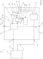
- Fig. 3 schematically illustrates an embodiment of the CAN transceiver 120 according to the present disclosure.
- the CAN transceiver 120 comprises a CAN BUS interface 130, a TXD interface 132, an RXD interface 134, a receiver 136, and a transmitter 138.
- the receiver 136 may be formed as a physical unit of the transceiver 120 and/or at least partially as a logical unit of the transceiver 120.
- the transmitter 138 may be formed as a physical unit of the transceiver 120 and/or at least partially as a logical unit of the transceiver 120.
- the receiver 136 is coupled between the CAN BUS interface 130 and the RXD interface 134. Preferably, the receiver 136 is directly coupled to both the CAN BUS interface 130 and the RXD interface 134.
- the transmitter 138 is coupled between the TXD interface 132 and the CAN BUS interface 130. Preferably, the transmitter 138 is directly coupled to both the TXD interface 132 and the CAN BUS interface 130. In an example, the transmitter 138 is connected to the TXD interface 132 via a signal connection. In an example, as shown for example in Figure 3 , the transmitter 138 is connected to the TXD interface 132 via a signal connection 204, a TXD signal error detector 196, and a signal connection 198.
- the transceiver 120 is configured to receive a digital TXD transmit signal via the TXD interface 132.
- the TXD transmit signal may also be referred to as the TXD signal.
- the TXD transmit signal may be transmitted from a CAN controller 114 to the TXD interface 132 via a signal connection 172.
- the TXD signal represents at least one frame. Each frame comprising a plurality of digital bits.
- the TXD transmit signal can reach the TXD signal error detector 196 via the TXD interface 132 and the signal connection 204.
- the TXD signal error detector 194 is configured to detect a sequence of at least six consecutive identical bits in the TXD transmit signal as a TXD error.
- the TXD signal error detector 196 may be configured to stop forwarding the TXD transmit signal to the signal connection 198 upon detection of the TXD error.
- the TXD signal error detector 196 may further be configured to forward the TXD transmit signal from the signal connection 204 to the signal connection 198 if the TXD signal error detector 196 does not detect a TXD error.
- the TXD signal error detector 196 may detect the TXD error based on a timeout of at least six consecutive equal bits. Therefore, in an example, the TXD signal error detector 196 may be configured as a timeout detector.
- a frame represented by the TXD transmit signal may reach the transmitter 138 via the TXD interface 132.
- the transmitter 138 is configured to generate a CAN BUS signal at the CAN BUS interface 130.
- the CAN BUS signal may be generated as a differential voltage signal between a first terminal 154 of the CAN BUS interface 130 and a second terminal 164 of the CAN BUS interface 130.
- a differential voltage of 0 V may represent a recessive bit" 1" and a differential voltage of 2 V may represent a dominant bit "0".
- the CAN BUS signal may represent the bits of the frame in a sequence.
- the transceiver 120 is configured to measure an electrical current of the transmitter 138.
- This electrical current is also referred to as the transmitter current.
- the transmitter 138 may generate the aforementioned differential voltage of 2 V between the two terminals 154, 156 such that a first actuation current flows over the signal connection 176 between the terminal 154 of the CAN BUS interface 130 and the transmitter 138 and a second actuation current flows over the signal connection 178 between the terminal 164 of the CAN BUS interface 31 and the transmitter 138.
- the first and second actuation currents may flow in reverse directions.
- first supply current may flow from the first supply terminal 156 of the transceiver 120 to the transmitter 138 and a second supply current to flow from the second supply terminal 158 of the transceiver 120 to the transmitter 138.
- the first and second supply currents may flow in reverse directions. Said currents are significantly higher if a dominant bit is generated at the CAN BUS interface 130 instead of a recessive bit.
- the transmitter 138 based on at least one of said electrical currents flowing into or out of the transmitter 138, it is derivable from at least one of the currents whether the transmitter 138 generates a dominant bit at the CAN BUS interface 130 or whether the transmitter does not generate a dominant bit, but preferably a recessive bit, at the CAN BUS interface 130.
- the transceiver 120 is configured to detect each dominant bit that is represented by the CAN BUS signal caused by the transmitter 138 based on the measured transmitter current.
- the transmitter current may be formed by at least one of the previously mentioned currents. Therefore, for a dominant bit, the transmitter current will be higher than for a recessive bit.
- the transceiver 120 may be configured to detect such a higher current and thereby detect a corresponding dominant bit.
- the transceiver 120 is further configured to detect an error sequence of at least six consecutive dominant bits, each detected based on the transmitter current.
- an error sequence of at least six consecutive dominant bits each detected based on the transmitter current.
- transceiver 120 may detect multiple consecutive dominant bits in the bit sequence.
- the transceiver 120 is further configured to detect the error sequence of at least six consecutive dominant bits in the bit sequence, if such an error sequence exists.
- the error sequence of at least six consecutive dominant bits corresponds to a break of the rules according to the CAN standard referred to in the introduction. Therefore, the error sequence of at least six consecutive dominant bits indicates that there is a fault in the transmitter 138.
- the transceiver 120 is configured to generate a control signal representing a fault of the transmitter 138 in response to a detected error sequence (of at least six consecutive dominant bits).
- the transceiver 120 may be configured to send and/or use the control signal to initiate follow-up actions. For example, based on the control signal, disabling the transmitter 138, the transceiver 120 and/or notifying the CAN controller 114 of the detected fault.
- security of the transceiver 120, the CAN controller 114, the CAN network 104, and/or the nodes 102 connected to the CAN network 104 may be improved.
- the TXD signal error detector 196 may be used to detect a TXD error in the TXD transmit signal. If a TXD error is detected by the TXD signal error detector 196, the TXD signal error detector 196 may prevent the TXD transmit signal from being forwarded to the transmitter 138. Thus, if the TXD transmit signal has a TXD error with at least six consecutive dominant bits, the TXD signal error detector 196 may effectively prevent the transmitter 138 from generating a CAN BUS signal at the CAN BUS 130 representing the TXD error.
- the TXD signal error detector 196 is not adapted to prevent or detect a fault of the transmitter 138.
- the transmitter 138 if the transmitter 138 exhibits a fault causing the transmitter 138 to generate a CAN BUS signal at the CAN BUS interface 130 representing an error sequence of at least six consecutive dominant bits, this fault of the transmitter 138 will be detected by the previously explained embodiment of the transceiver 120 and based on the transmitter current.
- the transceiver 120 is further configured to generate a control signal representing the detected fault of the transmitter 138.
- the transceiver 120 may use the control signal to disable the faulty transmitter 138.
- the CAN transceiver 120 may send the control signal to a CAN controller 114 to communicate the fault of the transmitter 138. The CAN controller 114 may then initiate follow-up actions.
- the transceiver 120 is preferably configured to detect a fault of the transmitter 138 by detecting the error sequence of at least six consecutive dominant bits represented by the CAN BUS signal.
- the error sequence may be detected by the transceiver 120 based on the transmitter current. Using the transmitter current to detect the error sequence has the advantage of detecting a fault of the transmitter 138 only if the error sequence is caused by the transmitter 138.
- a signal is transmitted from a remote node 102 to the CAN BUS interface 130 of the transceiver 120 via the CAN BUS 104, where the signal represents a sequence of at least six consecutive dominant bits
- these dominant bits will cause a transmitter current in the transmitter 138 with no current, or at most a low current, but not representative of dominant bits generated by the transmitter 138 itself. Therefore, the transceiver 120 will not detect the at least six consecutive dominant bits received as an error sequence based on the transmitter current. Rather, the transceiver 120 is preferably configured to detect an error sequence of at least six consecutive dominant bits based on the transmitter current only if those bits are self-generated by the transmitter 138. Detection of the potential fault of the transmitter 138 in response to a detected error sequence is therefore particularly robust to potential interference with and/or errors from remote CAN nodes 102.
- the transceiver 120 comprises a first sensor unit 150.
- the first sensor unit 150 is preferably arranged and/or configured to measure a first current to power the transmitter 138.
- the first current may also be referred to as a first supply current.
- the first current may form at least a part of the transmitter current of the transmitter 138.
- the transmitter current is formed by the first current.
- the first current is an electrical current.
- the transmitter 138 may comprise a first driver circuit.
- the first driver circuit may have a current demand that increases if a dominant bit is generated at the CAN BUS interface 130 by means of the transmitter 138.
- the increased current demand if the dominant bit is generated at the CAN BUS interface 130 will therefore be reflected in the value of the first current to supply the transmitter 138.
- the first current measured by means of the first sensor unit 150 may therefore be used to detect whether a dominant bit is generated at the CAN BUS interface 130 by means of the transmitter 138 or whether no dominant bit, thus in particular a recessive bit, is generated at the CAN BUS interface 130 by the transmitter 138.
- the transceiver 120 may be configured to detect any dominant bit represented by the CAN BUS signal generated by the transmitter 138 based on the first current.
- the transceiver 120 comprises a first supply terminal 156 and a second supply terminal 158 for supplying electrical power to the transceiver 120.
- the first sensor unit 150 may be coupled between the first supply terminal 156 and the transmitter 138.
- a first current flowing through the first supply terminal 156 to the transmitter 138 may be measured by the first sensor unit 150.
- the signal connection 192 may extend from the first supply terminal 156 to the first sensor unit 150.
- Another signal connection 200 may extend from the sensor unit 150 to the transmitter 138.
- the first current may flow from the first supply terminal 158 via the signal connection 192 to the first sensor unit 150 and from the first sensor unit 150 via the signal connection 200 to the transmitter 138.
- the preferred arrangement of the first sensor unit 150 between the first supply terminal 156 and the transmitter 138 can ensure that the first current measured by the first sensor unit 150 is caused solely by the transmitter 138. Therefore, the first current measurable by the first sensor unit 150 can be advantageously used by the transceiver 120 to detect whether the CAN BUS signal generated by the transmitter 138 represents a dominant bit. The detection is thereby particularly robust to possible bits sent to the transceiver 120 by means of a signal over the CAN BUS 104 from a remote node 102.
- the first sensor unit 150 is physically separate from the transmitter 138.
- the first sensor unit 150 may be physically separated from the transmitter 138 by the signal connection 200.
- the first sensor unit 150 may be partially or fully integrally formed with the transmitter 138.
- the transceiver 120 comprises a second sensor unit 160.
- the second sensor unit 160 is preferably arranged and/or configured to measure a second current to power the transmitter 138.
- the second current is an electrical current.
- the second current may also be referred to as a second supply current.
- the second current may form at least a part of the transmitter current of the transmitter 138.
- the transmitter current is formed by the second current.
- the transmitter 138 may comprise a second driver circuit.
- the second driver circuit may have a current demand that increases if a dominant bit is generated at the CAN BUS interface 130 by means of the transmitter 138.
- the increased current demand if the dominant bit is generated at the CAN BUS interface 130 will therefore be reflected in the value of the second current used to power the transmitter 138.
- the second current measured by means of the second sensor unit may therefore be used to detect whether a dominant bit is generated at the CAN BUS interface 130 by means of the transmitter 138 or whether no dominant bit, thus in particular a recessive bit, is generated at the CAN BUS interface 130.
- the transceiver 120 may be configured to detect any dominant bit represented by the CAN BUS signal generated by the transmitter 138 based on the second current.
- the transceiver 120 comprises a first supply terminal 156 and a second supply terminal 158 for supplying electrical power to the transceiver 120.
- the second sensor unit 160 may be coupled between the second supply terminal 158 and the transmitter 138.
- a second current flowing through the second supply terminal 158 to the transmitter 138 may be measured by the second sensor unit 160.
- the signal connection 194 may extend from the second supply terminal 158 to the second sensor unit 160.
- Another signal connection 202 may extend from the second sensor unit 160 to the transmitter 138.
- the second current may flow from the second supply terminal 158 to the second sensor unit 160 via the signal connection 194 and from the second sensor unit 160 to the transmitter 138 via the signal connection 202.
- the preferred arrangement of the second sensor unit 160 between the second supply terminal 158 and the transmitter 138 can ensure that the second current measured by the second sensor unit 160 is caused solely by the transmitter 138.
- the second current measurable by the second sensor unit 160 may therefore be advantageously used by the transceiver 120 to detect whether the CAN BUS signal generated by the transmitter 138 represents a dominant bit.
- the detection is particularly robust to possible bits sent to the transceiver 120 by means of a signal over the CAN BUS 104 from a remote node 102.
- the second sensor unit 160 is physically separate from the transmitter 138.
- the second sensor unit 160 may be physically separated from the transmitter 138 by the signal connection 202.
- the second sensor unit 160 may be partially or fully integrally formed with the transmitter 138.
- the first supply terminal 156 of the transceiver 120 is supplied with a first supply voltage, VCC.
- the second supply terminal 158 of the transceiver 120 may be supplied with a second supply voltage, in particular ground potential, Ground. If a CAN BUS signal representing a dominant bit is generated by the transmitter 138, the absolute value of the first current measured by the first sensor unit 150 may correspond to the absolute value of the second current measured by the second sensor unit. It may therefore be sufficient, in an example, for the transmitter current to be formed by either the first current or, alternatively, the second current.
- the transceiver 120 is configured to detect each dominant bit represented by the CAN BUS signal generated by the transmitter 138 based on the first current and the second current.
- both the first current and the second current may be considered by the transceiver 120.
- the detection may be robust to electromagnetic interference.
- the transceiver 120 comprises an evaluation unit 166.
- the evaluation unit 166 is coupled to at least one sensor unit 150, 160 of the two sensor units 150, 160.
- the evaluation unit 166 may be coupled to the first sensor unit 150 via a signal connection 180.
- the evaluation unit 166 may be coupled to the second sensor unit 160 via another signal connection 182.
- the evaluation unit 166 may be connected to only one of the two sensor units 150, 160 or to both sensor units 150, 160.
- Each sensor unit 150, 160 connected to the evaluation unit 166 may transmit a sensor signal to the evaluation unit 166.
- the first sensor unit 150 may transmit a first sensor signal representing the first current to the evaluation unit 166 via the signal connection 180.
- the evaluation unit 166 may be configured to compare the value of the first current to a predefined first current threshold. Further, the evaluation unit 166 may be configured to trigger a positive detection of a dominant bit represented by the CAN BUS signal generated by the transmitter 138 if the result of the comparison indicates that the value of the first current is higher than the first current threshold value. In an example, the evaluation unit 166 may be configured to not trigger a positive detection of a dominant bit (thus not represented by the CAN BUS signal generated by the transmitter 138) if the result of the comparison indicates that the value of the first current is less than the first current threshold.
- the second sensor unit 160 may transmit a second sensor signal representing the second current to the evaluation unit 166 via the further signal connection 182.
- the evaluation unit 166 may be configured to compare the value of the second current to a predefined second current threshold value. Further, the evaluation unit 166 may be configured to trigger a positive detection of a dominant bit represented by the CAN BUS signal generated by the transmitter 138 if the result of the comparison indicates that the value of the second current is higher than the second current threshold value. In an example, the evaluation unit 166 may be configured to not trigger a positive detection of a dominant bit (thus not represented by the CAN BUS signal generated by the transmitter 138) if the result of the comparison indicates that the value of the second current is less than the second current threshold.
- the evaluation unit 166 may be configured to trigger a positive detection of a dominant bit represented by the CAN BUS signal generated by the transmitter 138 if the result of the comparisons indicates that both the value of the first current is higher than the first current threshold and the value of the second current is higher than the second current threshold. In another example, the evaluation unit 166 may be configured not to trigger a positive detection of a dominant bit (thus not represented by the CAN BUS signal generated by the transmitter 138) if the result of the comparisons indicates that the value of the first current is less than the first current threshold and/or the value of the second current is less than the second current threshold.
- the CAN BUS signal generated by the transmitter 138 is preferably a differential voltage signal.
- a voltage swing of 2 V is required.
- increased currents flow between the transmitter 138 and the two terminals 154, 164 of the CAN BUS interface 130 is required. Therefore, to produce the voltage swing of 2 V, the transmitter 138 requires increased electrical power consumption, so that a higher first current and a higher second current will also flow.
- the transmitter 138 requires no or at most very low electrical power consumption, so that no or at most a very low first current and also no or at most a very low second current will flow.
- the first current threshold value may be defined such that the value of the first current is higher than the first current threshold value if the CAN BUS signal generated by the transmitter 138 represents a dominant bit. In an example, the first current threshold value may be defined such that the value of the first current is lower than the first current threshold value if the CAN BUS signal generated by the transmitter 138 represents a recessive bit. In an example, the second current threshold value may be defined such that the value of the second current is higher than second current threshold value if the bus signal generated by the transmitter 138 represents a dominant bit.
- the second current threshold value may be defined such that the value of the second current is lower than the second current threshold value if the CAN BUS signal generated by the transmitter 138 represents a recessive bit.
- Said values of the first and second currents preferably refer to the respective absolute values.
- the evaluation unit 166 provides the advantage of being able to detect a dominant bit represented by a CAN BUS signal generated by the transmitter 138 based on a comparison of the transmitter current, such as the first current, with a predefined threshold value for the current that would have to flow into or out of the transmitter 138 at a minimum to represent said dominant bit via the CAN BUS signal.
- the threshold value may be understood as a minimum value for the absolute value of transmitter current above which it is robustly detectable that a dominant bit is being transmitted via the CAN BUS signal generated by the transmitter 138.
- the evaluation unit 166 may detect the dominant bit based on an excess of the (absolute value) of the transmitter current drawn and/or caused by the transmitter 138 above the threshold value.
- the evaluation unit 166 of the transceiver 120 may be configured to detect each dominant bit represented by the CAN BUS signal generated by the transmitter 138 based on the transmitter current, preferably formed by the first current and/or second current.
- the transmitter current of the transmitter 138 may be formed by the current between the transmitter 138 and the first terminal 154 of the CAN BUS interface 130 and/or the current between the transmitter 138 and the second terminal 164 of the CAN BUS interface 130.
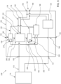
- Figure 4 schematically illustrates an example of a further embodiment of the CAN transceiver 120.
- the CAN transceiver 120 does not comprise the first sensor unit 150 or the second sensor unit 160.
- the CAN transceiver 120 may additionally be equipped with the first sensor unit 150 and/or the second sensor unit 160. If the CAN transceiver 120 is additionally equipped with the first sensor 150 and/or the second sensor 160, reference is made to the preceding explanations, preferred features, advantages and/or technical effects provided in connection with Figure 3 in an analogous manner.
- the design of the CAN transceiver 120 of Figure 4 corresponds in many details to the design of the CAN transceiver 120 of Figure 3 , so that reference for these details to the preceding explanations, preferred features, advantages and/or technical effects provided in connection with Figure 3 in an analogous manner.
- the transceiver 120 comprises a third sensor unit 205.
- the third sensor unit 205 is preferably arranged and/or configured to measure a third current between the transmitter 138 and the first terminal 154 of the CAN BUS interface 130.
- the third current may also be referred to as a third actuation current.
- the third current may form at least a part of the transmitter current of the transmitter 138.
- the third sensor unit 205 is coupled between a first output 152 of the transmitter 138 and the first terminal 154 of the CAN BUS interface 130.
- the CAN transceiver 120 may comprise a signal connection 184 extending from the first output 152 of the transmitter 138 to the third sensor unit 205.
- the CAN transceiver 120 may comprise another signal connection 186 extending from the third sensor unit 205 to the first terminal 154 of the CAN BUS interface 130.
- the signal connection 184, the third sensor unit 205, and the signal connection 186 may be connected in series to provide a connection between the first output 152 of the transmitter 138 and the first terminal 154 of the CAN BUS interface 130.
- the transceiver 120 comprises a fourth sensor unit 206.
- the fourth sensor unit 206 is preferably arranged and/or configured to measure a fourth current between the transmitter 138 and the second terminal 164 of the CAN BUS interface 130.
- the fourth current may also be referred to as a fourth actuation current.
- the fourth current may form at least a part of the transmitter current of the transmitter 138.
- the fourth sensor is coupled between a second output 162 of the transmitter 138 and the second terminal 164 of the CAN BUS interface 130.
- the CAN transceiver 120 may comprise a signal connection 188 extending from the first output 162 of the transmitter 138 to the fourth sensor unit 206.
- the CAN transceiver 120 may comprise another signal connection 190 extending from the fourth sensor unit 206 to the second terminal 164 of the CAN BUS interface 130.
- the signal connection 188, the fourth sensor unit 206, and the signal connection 190 may be connected in series to provide a connection between the second output 162 of the transmitter 138 and the second terminal 164 of the CAN BUS interface 130.
- the transceiver 120 comprises the evaluation unit 166.
- the evaluation unit 166 may be coupled to at least one sensor unit 205, 206 of the first and second sensor units 205, 206.
- the evaluation unit 166 may be coupled to at least one sensor unit 150, 160 of the first and second sensor units 150, 160, although this example will not be further explained for now.
- the following explanations preferably refer to the embodiment of the CAN transceiver of Fig. 4 .
- the evaluation unit 166 may be connected to the third sensor unit 205 via a signal connection 208. In an example, the evaluation unit 166 may be connected to the fourth sensor unit 206 via another signal connection 210. The evaluation unit 166 may be connected to one of the two sensor units 205, 206 or to both sensor units 205, 206. Each sensor unit 205, 206 connected to the evaluation unit 166 may transmit a sensor signal to the evaluation unit 166.
- the third sensor unit 204 may transmit via the signal connection 208 a third sensor signal representing the third current to the evaluation unit 166.
- the evaluation unit 166 may be configured to compare the value of the third current to a predefined third current threshold value. Further, the evaluation unit 166 may be configured to trigger a positive detection of a dominant bit represented by the CAN BUS signal generated by the transmitter 138 if the result of the comparison indicates that the value of the third current is higher than the third current threshold value. In an example, the evaluation unit 166 may be configured to not trigger a positive detection of a dominant bit (thus not represented by the CAN BUS signal generated by the transmitter 138) if the result of the comparison indicates that the value of the third current is less than the third current threshold value.
- the fourth sensor unit 206 may transmit via the further signal connection 210 a fourth sensor signal representing the fourth current to the evaluation unit 166.
- the evaluation unit 166 may be configured to compare the value of the fourth current to a predefined fourth current threshold value. Further, the evaluation unit 166 may be configured to trigger a positive detection of a dominant bit represented by the CAN BUS signal generated by the transmitter 138 if the result of the comparison indicates that the value of the fourth current is higher than the fourth current threshold value. In an example, the evaluation unit 166 may be configured to not trigger a positive detection of a dominant bit (thus not represented by the CAN BUS signal generated by the transmitter 138) if the result of the comparison indicates that the value of the fourth current is less than the fourth current threshold value.
- the evaluation unit 166 may be configured to trigger a positive detection of a dominant bit represented by the CAN BUS signal generated by the transmitter 138 if the result of the comparisons indicates that both the value of the third current is higher than the third current threshold value and the value of the fourth current is higher than the fourth current threshold value. In another example, the evaluation unit 166 may be configured not to trigger a positive detection of a dominant bit (thus not represented by the CAN BUS signal generated by the transmitter 138) if the result of the comparisons indicates that the value of the third current is less than the third current threshold and/or if the value of the fourth current is also less than the fourth current threshold.
- the transceiver 120 is configured to detect a first duration of a plurality of consecutive dominant bits.
- the bits are dominant bits detected based on the transmitter current generated by the transmitter 138.
- the evaluation unit 166 of the transceiver 120 is configured to detect the first duration of the plurality of detected, consecutive dominant bits.
- the evaluation unit 166 is configured to compare the first time duration to a predefined reference time duration.
- the evaluation unit 166 is configured to trigger a positive detection of the error sequence (of at least six consecutive dominant bits being detected) if the result of the comparison indicates that the first time duration is larger (longer) than the reference time duration.
- the time duration of each bit is approximately the same.
- the evaluation unit 166 detects a first time duration that is lager (longer) than five times the time duration of a single bit, it may be derived that the first time duration has the duration of at least six consecutive dominant bits being detected.
- the predefined reference duration may be understood as a threshold for the first duration to detect the error sequence of at least six consecutive dominant bits.
- the error sequence is determined by at least six consecutive dominant bits because it is specified in the CAN standard that a maximum of five identical consecutive bits may be generated and/or transmitted during error-free operation. A break of this rule defined in the CAN standard leads to the conclusion that an error is present.
- the predefined reference duration is at least five times the time duration of a single bit and preferably less than six times the duration of a single bit. In an example, the predefined reference duration may be 5.5 times the time duration of a single bit.
- the evaluation unit 166 of the transceiver 120 is configured to generate the control signal representing a fault of the transmitter 138 in response to a detected error sequence.
- the error sequence is detected if a first time duration is higher than the predefined reference time duration.
- at least six consecutive dominant bits have represented by a CAN BUS signal been generated by the transmitter 138, such that an erroneous behavior of the transmitter 138 is present.
- the erroneous behavior of the transmitter 138 can also be referred to as a fault of the transmitter 138.
- the control signal may be configured to directly or indirectly represent the fault of the transmitter 138.
- the control signal may be sent from the evaluation unit 166 of the transceiver 120 to the CAN controller 114 to inform the CAN controller 114 of the fault of the transmitter 138.
- FIG. 5 schematically illustrates an example of a further embodiment of the transceiver 120, wherein the transceiver 120 is based on the embodiment of the transceiver 120 of Figure 4 and/or Figure 3 . Therefore, for the embodiment of the transceiver 120 of Figure 5 , reference is made to the preferred explanations, preferred features, technical effects and advantages as explained for the transceiver 120 of Figure 4 and/or Figure 3 .
- the transceiver 120 comprises another signal interface 214.
- the transceiver 120 may further comprise a signal connection 216 extending from the evaluation unit 166 to the signal interface 214.
- the evaluation unit 166 is preferably configured to direct the control signal to the signal interface 214 via the signal connection 216, such that the control signal may be transmitted via the signal interface 214.
- the CAN controller 214 is coupled to the signal interface 214 of the transceiver 120 via another signal connection 212. In this case, the evaluation unit 166 may send the control signal to the CAN controller 114 via the signal connection 216, the signal interface 214, and the signal connection 212.
- the control signal may represent the faulty state of the transmitter 138.
- the CAN controller 114 may be informed of the fault of the transmitter 138 of the transceiver 120 via the control signal.
- the CAN controller 114 may initiate follow-up actions in response to the fault of the transmitter 138.
- the CAN controller 114 may interrupt and/or block the transmission of a TXD transmission signal to the TXD interface 132 of the transceiver and/or the reception of an RXD signal from the RXD interface 134.
- the CAN controller 114 may inform a higher-level control unit (not shown) in response to the fault of the transmitter 138.
- the CAN controller 114 and the CAN transceiver 120 may be comprised by a CAN system 228.
- Figures 6 and 7 each schematically illustrate an example of a further embodiment of the transceiver 120, preferably based on the embodiment of the transceiver 120 of Figure 4 and/or Figure 3 . Therefore, for the embodiment of the transceiver 120 of Figure 6 and/or Figure 7 , reference is made in each case to the preferred explanations, preferred features, technical effects and advantages as explained for the transceiver 120 of Figure 4 and/or Figure 3 . Purely as a precaution, it is pointed out that the embodiment of the transceiver 120 of Figure 6 may, in an example, further comprise the features of the transceiver 120 previously mentioned in connection with Figure 5 .
- the evaluation unit 166 may be configured to generate the control signal in response to a detected error sequence such that the fault of the transmitter 138 is indirectly represented by the control signal.
- the control signal may represent a control command to disable the transmitter 138 and/or a control command to activate a shutdown unit to disable the transmitter 138.
- the transceiver 120 comprises at least one shutdown unit 218, 220.
- each shutdown unit 218, 220 is configured to at least partially disable the transmitter 138 based on the control signal.
- the evaluation unit 166 is coupled to each shutdown unit 218, 220 to send the control signal to each of the at least one shutdown unit 218, 220.
- a first shutdown unit 218 is integrated into the first sensor unit 150.
- a first shutdown unit 218 is not or not fully integrated into the first sensor unit 150.
- the transceiver 120 comprises another signal connection 224 extending from the evaluation unit 166 to the first shutdown unit 218.
- the evaluation unit 166 may be configured to send the control signal to the first shutdown unit 218 via the signal connection 224.
- the first shutdown unit 218 is configured to interrupt the electrical connection between the first supply terminal 156 of the transceiver 120 and the transmitter 138 based on the control signal.
- the first shutdown unit 218 may interrupt the electrical connection between the first supply terminal 156 of the transceiver 120 and the transmitter 138 in response to the received control signal.
- the control signal does not represent a control command to disable the transmitter 138 or if no control command is generated by the evaluation unit 166, the first shutdown unit 218 may be configured in this case to not interrupt the electrical connection between the first supply terminal 156 of the transceiver 120 and the transmitter 138.
- a second shutdown unit 220 is integrated into the second sensor unit 160.
- a second shutdown unit 220 is not or not fully integrated into the second sensor unit 160.
- the transceiver 120 comprises another signal connection 222 extending from the evaluation unit 166 to the second shutdown unit 220.
- the evaluation unit 166 may be configured to send the control signal to the second shutdown unit 220 via the signal connection 222.
- the second shutdown unit 220 is configured to interrupt the electrical connection between the second supply terminal 158 of the transceiver 120 and the transmitter 138 based on the control signal.
- the second shutdown unit 220 may interrupt the electrical connection between the second supply terminal 158 of the transceiver 120 and the transmitter 138 in response to the received control signal.
- the control signal does not represent a control command to disable the transmitter 138 or if no control command is generated by the evaluation unit 166, the second shutdown unit 220 may be configured in this case to not interrupt the electrical connection between the first supply terminal 158 of the transceiver 120 and the transmitter 138.
- the CAN transceiver 120 comprises the first shutdown unit 218 and the second shutdown unit 220, wherein the two shutdown units 218, 220 are configured to jointly disable the transmitter 138 based on the control signal.
- the two shutdown units 218, 220 may be configured to jointly completely interrupt the transmitter 138 from the first and second supply terminals 156, 158 based on the control signal.
- the evaluation unit 166 may control the first and second shutdown units 218, 220 via the control signal so that the two shutdown units 218, 220 fully disable the transmitter 138.
- the disabling can effectively prevent the (faulty) transmitter 138 from blocking the CAN BUS 104 by sending out dominant bits or adversely affecting nodes 102 coupled to the CAN BUS 104.
- the CAN transmitter 138 may remain disabled until a next power cycle of the transceiver 120.
- the evaluation unit may reset the control signal upon a predefined interruption time.
- the evaluation unit 166 may be configured to check again, whether the fault of the transmitter 138 disappeared. If not, the evaluation unit 166 may change into a locked state, where the evaluation unit sends out the control signal independent of whether the transmitter 138 recovers
- the CAN transceiver 120 may be configured to re-enabling the transmitter 138 again after a predefined waiting period (following the disabling of the transmitter 138) and preferably also configured to check if the fault of the transmitter 138 occurs again.
- the number of re-enablings may be limited to a predefined number.
- FIG 8 schematically illustrates an example of a further embodiment of the transceiver 120, preferably based on the embodiment of the transceiver 120 of any of Figures 3 to 7 . Therefore, for the embodiment of the transceiver 120 of Figure 8 , reference is made to the preferred explanations, preferred features, technical effects and advantages as explained for the transceiver 120 to the previous figures.
- the transceiver 120 may comprise a TXD signal error detector 196.
- the TXD transmit signal from the CAN controller 114 can reach the TXD signal error detector 196 via the TXD interface 132 and the signal connection 194.
- the TXD signal error detector 196 is configured to detect a sequence of at least six consecutive identical bits in the TXD transmit signal as a TXD error.
- the TXD signal error detector 196 may be configured to stop forwarding the TXD transmit signal to the signal connection 198 upon detecting the TXD error.
- the TXD signal error detector 196 may further be configured to forward the TXD transmit signal from the signal connection 194 to the signal connection 198 if the TXD signal error detector 196 does not detect a TXD error.
- the TXD signal error detector 196 has the advantage that preferably no erroneous TXD transmit signal reaches the transmitter 138. If, nevertheless, a CAN BUS signal is generated by the transmitter 138 that represents a sequence of six consecutive dominant bits, it can be derived that there is a fault of the transmitter 138. This fault of the transmitter 138 may be detected by means of an embodiment of the transceiver 120, as previously explained with reference to Figures 3-7 .
- a further fault of the transmitter 138 may occur if the TXD transmit signal arriving at the transmitter 138 via the signal connection 198 represents a dominant bit, but a CAN BUS signal is generated by the transmitter 138 that does not represent said dominant bit.
- the evaluation unit 166 is coupled to the TXD interface 132 of the transceiver 120 to receive the digital TXD transmit signal.
- the transceiver 120 may comprise another signal connection 226 extending from the signal connection 198 to the evaluation unit 166. As a result the digital TXD transmit signal preferably reaches both the transmitter 138 and the evaluation unit 166.
- the evaluation unit 166 is configured to observe whether a dominant bit represented by the TXD transmit signal is also represented as a dominant bit by the CAN BUS signal. As previously explained, the evaluation unit 166 is preferably configured to detect any dominant bit represented by the CAN BUS signal based on the transmitter current. Preferably, the evaluation unit 166 is configured to detect each dominant bit that is represented by the TXD transmit signal. In an example, the evaluation unit 166 may be configured to observe whether a dominant bit detected in the TXD transmit signal is also represented as a dominant bit by the CAN BUS signal.
- the evaluation unit 166 is configured to trigger a positive detection of a transmission error if the result of the observation indicates that a dominant bit represented by the TXD digital transmit signal is not also represented by the CAN BUS signal.
- the transmission error may be another example of an fault of the transmitter 138.
- the evaluation unit 166 of the transceiver 120 may be configured to (also) generate the control signal in response to a positive detection of the transmission error.
- the control signal may directly or indirectly represent the fault of the transmitter 138.
- the transceiver 120 and preferably the evaluation unit 166 of the transceiver 120, is configured to send an error signal to the CAN controller 114 via the interface 214 of the transceiver 120 in response to a detected error sequence and/or in response to a detected transmission error.
- the error signal may differ from the control signal.
- the error signal may directly or indirectly represent the detected error sequence, the detected transmission error, and/or generally the fault of the transmitter 138.
- the transceiver 120 and preferably the evaluation unit 166 of the transceiver 120, is configured to generate the control signal in response to the detected error sequence and/or in response to a detected transmission error. Further, the evaluation unit 166 may be configured to control the at least one shutdown unit 218, 220 via the control signal such that the respective shutdown unit 218, 220 fully or at least partially disables the transmitter 138 in response to the control signal.
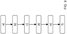
- FIG. 9 schematically illustrates an example of an embodiment of the method according to the present disclosure.
- the method is for a CAN transceiver 120 having a CAN BUS interface 130, a TXD interface 132, an RXD interface 134, a receiver 136 coupled to the CAN BUS interface 130 and the RXD interface 134, and a transmitter 138 coupled to the TXD interface 132 and the CAN BUS interface 130, the method comprising the following steps a) through f): a) Receiving a digital TXD transmit signal, representing a frame comprising a plurality of bits, over the TXD interface 132 from a CAN controller 114; b) Generate a CAN BUS signal that represents the bits of the frame in a sequence at the CAN BUS interface 130; c) Measuring an electrical current of the transmitter 138, referred to as the transmitter current; d) Detect each dominant bit represented by the CAN BUS signal based on the transmitter current; e) Detecting
- the systems and methods described herein may at least partially be embodied by a computer program or a plurality of computer programs, which may exist in a variety of forms both active and inactive in a single computer system or across multiple computer systems.
- they may exist as software program(s) comprised of program instructions in source code, object code, executable code or other formats for performing some of the steps.
- Any of the above may be embodied on a computer-readable medium, which may include storage devices and signals, in compressed or uncompressed form.
- the term "computer” refers to any electronic device comprising a processor, such as a general-purpose central processing unit (CPU), a specific-purpose processor or a microcontroller.
- a computer is capable of receiving data (an input), of performing a sequence of predetermined operations thereupon, and of producing thereby a result in the form of information or signals (an output).
- the term "computer” will mean either a processor in particular or more generally a processor in association with an assemblage of interrelated elements contained within a single case or housing.
- processor or “processing unit” refers to a data processing circuit that may be a microprocessor, a co-processor, a microcontroller, a microcomputer, a central processing unit, a field programmable gate array (FPGA), a programmable logic circuit, and/or any circuit that manipulates signals (analog or digital) based on operational instructions that are stored in a memory.
- memory refers to a storage circuit or multiple storage circuits such as read-only memory, random access memory, volatile memory, non-volatile memory, static memory, dynamic memory, Flash memory, cache memory, and/or any circuit that stores digital information.
- a "computer-readable medium” or “storage medium” may be any means that can contain, store, communicate, propagate, or transport a computer program for use by or in connection with the instruction execution system, apparatus, or device.
- the computer-readable medium may be, for example but not limited to, an electronic, magnetic, optical, electromagnetic, infrared, or semiconductor system, apparatus, device, or propagation medium.
- the computer-readable medium may include the following: an electrical connection having one or more wires, a portable computer diskette, a random-access memory (RAM), a read-only memory (ROM), an erasable programmable read-only memory (EPROM or Flash memory), an optical fiber, a portable compact disc read-only memory (CDROM), a digital versatile disc (DVD), a Blu-ray disc (BD), and a memory card.
- RAM random-access memory
- ROM read-only memory
- EPROM or Flash memory erasable programmable read-only memory
- CDROM compact disc read-only memory
- DVD digital versatile disc
- BD Blu-ray disc
Landscapes
- Engineering & Computer Science (AREA)
- Computer Networks & Wireless Communication (AREA)
- Signal Processing (AREA)
- General Engineering & Computer Science (AREA)
- Theoretical Computer Science (AREA)
- Environmental & Geological Engineering (AREA)
- Computer Hardware Design (AREA)
- Physics & Mathematics (AREA)
- General Physics & Mathematics (AREA)
- Small-Scale Networks (AREA)
Priority Applications (3)
| Application Number | Priority Date | Filing Date | Title |
|---|---|---|---|
| EP22192034.1A EP4329247B1 (fr) | 2022-08-24 | 2022-08-24 | Émetteur-récepteur de réseau de zone de contrôleur et procédé pour l'émetteur-récepteur |
| CN202310821827.8A CN117640280A (zh) | 2022-08-24 | 2023-07-05 | 控制器局域网收发器和用于收发器的方法 |
| US18/361,702 US12561265B2 (en) | 2022-08-24 | 2023-07-28 | Controller area network transceiver and method for the transceiver |
Applications Claiming Priority (1)
| Application Number | Priority Date | Filing Date | Title |
|---|---|---|---|
| EP22192034.1A EP4329247B1 (fr) | 2022-08-24 | 2022-08-24 | Émetteur-récepteur de réseau de zone de contrôleur et procédé pour l'émetteur-récepteur |
Publications (2)
| Publication Number | Publication Date |
|---|---|
| EP4329247A1 true EP4329247A1 (fr) | 2024-02-28 |
| EP4329247B1 EP4329247B1 (fr) | 2025-04-16 |
Family
ID=83080855
Family Applications (1)
| Application Number | Title | Priority Date | Filing Date |
|---|---|---|---|
| EP22192034.1A Active EP4329247B1 (fr) | 2022-08-24 | 2022-08-24 | Émetteur-récepteur de réseau de zone de contrôleur et procédé pour l'émetteur-récepteur |
Country Status (3)
| Country | Link |
|---|---|
| US (1) | US12561265B2 (fr) |
| EP (1) | EP4329247B1 (fr) |
| CN (1) | CN117640280A (fr) |
Families Citing this family (1)
| Publication number | Priority date | Publication date | Assignee | Title |
|---|---|---|---|---|
| JP2025105150A (ja) * | 2023-12-28 | 2025-07-10 | 株式会社デンソー | 通信レシーバ |
Citations (2)
| Publication number | Priority date | Publication date | Assignee | Title |
|---|---|---|---|---|
| US20180041358A1 (en) * | 2016-08-05 | 2018-02-08 | Denso Corporation | Communications device |
| US20200287746A1 (en) * | 2019-03-06 | 2020-09-10 | Toyota Jidosha Kabushiki Kaisha | Communication failure detection device |
Family Cites Families (9)
| Publication number | Priority date | Publication date | Assignee | Title |
|---|---|---|---|---|
| US8699356B2 (en) * | 2010-12-20 | 2014-04-15 | Deere & Company | Method and system for diagnosing a fault or open circuit in a network |
| JP6063606B2 (ja) * | 2014-04-03 | 2017-01-18 | パナソニック インテレクチュアル プロパティ コーポレーション オブ アメリカPanasonic Intellectual Property Corporation of America | ネットワーク通信システム、不正検知電子制御ユニット及び不正対処方法 |
| EP3133774B1 (fr) * | 2014-04-17 | 2020-11-25 | Panasonic Intellectual Property Corporation of America | Système de réseau monté sur un véhicule, unité de commande électronique de détection d'anomalie et procédé de détection d'anomalie |
| US9935774B2 (en) * | 2015-05-22 | 2018-04-03 | Nxp B.V. | Configurable cryptographic controller area network (CAN) device |
| US10310934B2 (en) * | 2017-04-27 | 2019-06-04 | GM Global Technology Operations LLC | Methods and systems for diagnosing a controller area network |
| DE102017212544A1 (de) * | 2017-07-21 | 2019-01-24 | Robert Bosch Gmbh | Sende-/Empfangseinrichtung für ein CAN Bussystem und Verfahren zur Erkennung eines Kurzschlusses mit einer CAN Sende-/Empfangseinrichtung |
| JP7176564B2 (ja) * | 2018-04-27 | 2022-11-22 | 日本電気株式会社 | 監視装置、および、監視方法 |
| JP7178408B2 (ja) * | 2018-05-23 | 2022-11-25 | パナソニック インテレクチュアル プロパティ コーポレーション オブ アメリカ | 異常検出装置、異常検出システム及び制御方法 |
| US10884069B2 (en) * | 2018-08-10 | 2021-01-05 | Texas Instruments Incorporated | Control area network (CAN) bus fault detection |
-
2022
- 2022-08-24 EP EP22192034.1A patent/EP4329247B1/fr active Active
-
2023
- 2023-07-05 CN CN202310821827.8A patent/CN117640280A/zh active Pending
- 2023-07-28 US US18/361,702 patent/US12561265B2/en active Active
Patent Citations (2)
| Publication number | Priority date | Publication date | Assignee | Title |
|---|---|---|---|---|
| US20180041358A1 (en) * | 2016-08-05 | 2018-02-08 | Denso Corporation | Communications device |
| US20200287746A1 (en) * | 2019-03-06 | 2020-09-10 | Toyota Jidosha Kabushiki Kaisha | Communication failure detection device |
Also Published As
| Publication number | Publication date |
|---|---|
| CN117640280A (zh) | 2024-03-01 |
| US20240070099A1 (en) | 2024-02-29 |
| US12561265B2 (en) | 2026-02-24 |
| EP4329247B1 (fr) | 2025-04-16 |
Similar Documents
| Publication | Publication Date | Title |
|---|---|---|
| US12212430B2 (en) | Controller area network transceiver and method for the transceiver | |
| US11463198B2 (en) | Security module for a serial communications device | |
| US12261715B2 (en) | CAN module, CAN transceiver, CAN system and method for CAN module | |
| US12425066B2 (en) | CAN transceiver and method for the CAN transceiver | |
| US12314203B2 (en) | Can controller, can device and method for the can controller | |
| US12561265B2 (en) | Controller area network transceiver and method for the transceiver | |
| US12494939B2 (en) | Apparatus for a controller area network | |
| US12261716B2 (en) | Controller area network system and a method for the system | |
| JP4968169B2 (ja) | 通信システム及び通信方法 | |
| US12028184B2 (en) | Controller area network module and method for the module | |
| EP4376364B1 (fr) | Émetteur-récepteur can et procédé pour l'émetteur-récepteur can | |
| EP4300897A1 (fr) | Noeud de réseau de zone de contrôleur, système can et procédé pour le noeud | |
| EP4730712A1 (fr) | Système de communication, dispositifs du système de communication et procédé pour le dispositif | |
| EP4304135A1 (fr) | Émetteur-récepteur de réseau de zone de contrôleur (can), noeud can, système can et procédé pour l'émetteur-récepteur can |
Legal Events
| Date | Code | Title | Description |
|---|---|---|---|
| PUAI | Public reference made under article 153(3) epc to a published international application that has entered the european phase |
Free format text: ORIGINAL CODE: 0009012 |
|
| STAA | Information on the status of an ep patent application or granted ep patent |
Free format text: STATUS: THE APPLICATION HAS BEEN PUBLISHED |
|
| AK | Designated contracting states |
Kind code of ref document: A1 Designated state(s): AL AT BE BG CH CY CZ DE DK EE ES FI FR GB GR HR HU IE IS IT LI LT LU LV MC MK MT NL NO PL PT RO RS SE SI SK SM TR |
|
| STAA | Information on the status of an ep patent application or granted ep patent |
Free format text: STATUS: REQUEST FOR EXAMINATION WAS MADE |
|
| 17P | Request for examination filed |
Effective date: 20240828 |
|
| RBV | Designated contracting states (corrected) |
Designated state(s): AL AT BE BG CH CY CZ DE DK EE ES FI FR GB GR HR HU IE IS IT LI LT LU LV MC MK MT NL NO PL PT RO RS SE SI SK SM TR |
|
| REG | Reference to a national code |
Ref country code: DE Free format text: PREVIOUS MAIN CLASS: H04L0012400000 Ref country code: DE Ref legal event code: R079 Ref document number: 602022013170 Country of ref document: DE Free format text: PREVIOUS MAIN CLASS: H04L0012400000 Ipc: H04L0043080000 |
|
| GRAP | Despatch of communication of intention to grant a patent |
Free format text: ORIGINAL CODE: EPIDOSNIGR1 |
|
| STAA | Information on the status of an ep patent application or granted ep patent |
Free format text: STATUS: GRANT OF PATENT IS INTENDED |
|
| RIC1 | Information provided on ipc code assigned before grant |
Ipc: H04L 12/40 20060101ALI20241130BHEP Ipc: H04L 43/16 20220101ALI20241130BHEP Ipc: H04L 43/0823 20220101ALI20241130BHEP Ipc: H04L 43/0817 20220101ALI20241130BHEP Ipc: H04L 43/08 20220101AFI20241130BHEP |
|
| INTG | Intention to grant announced |
Effective date: 20241218 |
|
| GRAS | Grant fee paid |
Free format text: ORIGINAL CODE: EPIDOSNIGR3 |
|
| GRAA | (expected) grant |
Free format text: ORIGINAL CODE: 0009210 |
|
| STAA | Information on the status of an ep patent application or granted ep patent |
Free format text: STATUS: THE PATENT HAS BEEN GRANTED |
|
| RIN1 | Information on inventor provided before grant (corrected) |
Inventor name: KWAKERNAAT, GERALD Inventor name: VAN DIJK, LUCAS PIETER LODEWIJK |
|
| AK | Designated contracting states |
Kind code of ref document: B1 Designated state(s): AL AT BE BG CH CY CZ DE DK EE ES FI FR GB GR HR HU IE IS IT LI LT LU LV MC MK MT NL NO PL PT RO RS SE SI SK SM TR |
|
| REG | Reference to a national code |
Ref country code: GB Ref legal event code: FG4D |
|
| REG | Reference to a national code |
Ref country code: CH Ref legal event code: EP |
|
| REG | Reference to a national code |
Ref country code: IE Ref legal event code: FG4D |
|
| REG | Reference to a national code |
Ref country code: DE Ref legal event code: R096 Ref document number: 602022013170 Country of ref document: DE |
|
| PG25 | Lapsed in a contracting state [announced via postgrant information from national office to epo] |
Ref country code: NL Free format text: LAPSE BECAUSE OF FAILURE TO SUBMIT A TRANSLATION OF THE DESCRIPTION OR TO PAY THE FEE WITHIN THE PRESCRIBED TIME-LIMIT Effective date: 20250416 |
|
| REG | Reference to a national code |
Ref country code: AT Ref legal event code: MK05 Ref document number: 1786610 Country of ref document: AT Kind code of ref document: T Effective date: 20250416 |
|
| PG25 | Lapsed in a contracting state [announced via postgrant information from national office to epo] |
Ref country code: FI Free format text: LAPSE BECAUSE OF FAILURE TO SUBMIT A TRANSLATION OF THE DESCRIPTION OR TO PAY THE FEE WITHIN THE PRESCRIBED TIME-LIMIT Effective date: 20250416 Ref country code: PT Free format text: LAPSE BECAUSE OF FAILURE TO SUBMIT A TRANSLATION OF THE DESCRIPTION OR TO PAY THE FEE WITHIN THE PRESCRIBED TIME-LIMIT Effective date: 20250818 Ref country code: ES Free format text: LAPSE BECAUSE OF FAILURE TO SUBMIT A TRANSLATION OF THE DESCRIPTION OR TO PAY THE FEE WITHIN THE PRESCRIBED TIME-LIMIT Effective date: 20250416 |
|
| PGFP | Annual fee paid to national office [announced via postgrant information from national office to epo] |
Ref country code: DE Payment date: 20250724 Year of fee payment: 4 |
|
| REG | Reference to a national code |
Ref country code: LT Ref legal event code: MG9D |
|
| PG25 | Lapsed in a contracting state [announced via postgrant information from national office to epo] |
Ref country code: GR Free format text: LAPSE BECAUSE OF FAILURE TO SUBMIT A TRANSLATION OF THE DESCRIPTION OR TO PAY THE FEE WITHIN THE PRESCRIBED TIME-LIMIT Effective date: 20250717 Ref country code: NO Free format text: LAPSE BECAUSE OF FAILURE TO SUBMIT A TRANSLATION OF THE DESCRIPTION OR TO PAY THE FEE WITHIN THE PRESCRIBED TIME-LIMIT Effective date: 20250716 |
|
| PG25 | Lapsed in a contracting state [announced via postgrant information from national office to epo] |
Ref country code: PL Free format text: LAPSE BECAUSE OF FAILURE TO SUBMIT A TRANSLATION OF THE DESCRIPTION OR TO PAY THE FEE WITHIN THE PRESCRIBED TIME-LIMIT Effective date: 20250416 |
|
| PG25 | Lapsed in a contracting state [announced via postgrant information from national office to epo] |
Ref country code: BG Free format text: LAPSE BECAUSE OF FAILURE TO SUBMIT A TRANSLATION OF THE DESCRIPTION OR TO PAY THE FEE WITHIN THE PRESCRIBED TIME-LIMIT Effective date: 20250416 |
|
| PG25 | Lapsed in a contracting state [announced via postgrant information from national office to epo] |
Ref country code: HR Free format text: LAPSE BECAUSE OF FAILURE TO SUBMIT A TRANSLATION OF THE DESCRIPTION OR TO PAY THE FEE WITHIN THE PRESCRIBED TIME-LIMIT Effective date: 20250416 |
|
| PG25 | Lapsed in a contracting state [announced via postgrant information from national office to epo] |
Ref country code: AT Free format text: LAPSE BECAUSE OF FAILURE TO SUBMIT A TRANSLATION OF THE DESCRIPTION OR TO PAY THE FEE WITHIN THE PRESCRIBED TIME-LIMIT Effective date: 20250416 |
|
| PGFP | Annual fee paid to national office [announced via postgrant information from national office to epo] |
Ref country code: FR Payment date: 20250723 Year of fee payment: 4 |
|
| PG25 | Lapsed in a contracting state [announced via postgrant information from national office to epo] |
Ref country code: RS Free format text: LAPSE BECAUSE OF FAILURE TO SUBMIT A TRANSLATION OF THE DESCRIPTION OR TO PAY THE FEE WITHIN THE PRESCRIBED TIME-LIMIT Effective date: 20250716 |
|
| PG25 | Lapsed in a contracting state [announced via postgrant information from national office to epo] |
Ref country code: IS Free format text: LAPSE BECAUSE OF FAILURE TO SUBMIT A TRANSLATION OF THE DESCRIPTION OR TO PAY THE FEE WITHIN THE PRESCRIBED TIME-LIMIT Effective date: 20250816 |
|
| PG25 | Lapsed in a contracting state [announced via postgrant information from national office to epo] |
Ref country code: LV Free format text: LAPSE BECAUSE OF FAILURE TO SUBMIT A TRANSLATION OF THE DESCRIPTION OR TO PAY THE FEE WITHIN THE PRESCRIBED TIME-LIMIT Effective date: 20250416 |
|
| PG25 | Lapsed in a contracting state [announced via postgrant information from national office to epo] |
Ref country code: DK Free format text: LAPSE BECAUSE OF FAILURE TO SUBMIT A TRANSLATION OF THE DESCRIPTION OR TO PAY THE FEE WITHIN THE PRESCRIBED TIME-LIMIT Effective date: 20250416 Ref country code: SM Free format text: LAPSE BECAUSE OF FAILURE TO SUBMIT A TRANSLATION OF THE DESCRIPTION OR TO PAY THE FEE WITHIN THE PRESCRIBED TIME-LIMIT Effective date: 20250416 |
|
| REG | Reference to a national code |
Ref country code: DE Ref legal event code: R097 Ref document number: 602022013170 Country of ref document: DE |
|
| PG25 | Lapsed in a contracting state [announced via postgrant information from national office to epo] |
Ref country code: CZ Free format text: LAPSE BECAUSE OF FAILURE TO SUBMIT A TRANSLATION OF THE DESCRIPTION OR TO PAY THE FEE WITHIN THE PRESCRIBED TIME-LIMIT Effective date: 20250416 |
|
| PG25 | Lapsed in a contracting state [announced via postgrant information from national office to epo] |
Ref country code: EE Free format text: LAPSE BECAUSE OF FAILURE TO SUBMIT A TRANSLATION OF THE DESCRIPTION OR TO PAY THE FEE WITHIN THE PRESCRIBED TIME-LIMIT Effective date: 20250416 |
|
| PG25 | Lapsed in a contracting state [announced via postgrant information from national office to epo] |
Ref country code: SK Free format text: LAPSE BECAUSE OF FAILURE TO SUBMIT A TRANSLATION OF THE DESCRIPTION OR TO PAY THE FEE WITHIN THE PRESCRIBED TIME-LIMIT Effective date: 20250416 |
|
| PG25 | Lapsed in a contracting state [announced via postgrant information from national office to epo] |
Ref country code: IT Free format text: LAPSE BECAUSE OF FAILURE TO SUBMIT A TRANSLATION OF THE DESCRIPTION OR TO PAY THE FEE WITHIN THE PRESCRIBED TIME-LIMIT Effective date: 20250416 |
|
| PLBE | No opposition filed within time limit |
Free format text: ORIGINAL CODE: 0009261 |
|
| STAA | Information on the status of an ep patent application or granted ep patent |
Free format text: STATUS: NO OPPOSITION FILED WITHIN TIME LIMIT |
|
| REG | Reference to a national code |
Ref country code: CH Ref legal event code: L10 Free format text: ST27 STATUS EVENT CODE: U-0-0-L10-L00 (AS PROVIDED BY THE NATIONAL OFFICE) Effective date: 20260225 |
|
| PG25 | Lapsed in a contracting state [announced via postgrant information from national office to epo] |
Ref country code: RO Free format text: LAPSE BECAUSE OF FAILURE TO SUBMIT A TRANSLATION OF THE DESCRIPTION OR TO PAY THE FEE WITHIN THE PRESCRIBED TIME-LIMIT Effective date: 20250416 |
|
| REG | Reference to a national code |
Ref country code: CH Ref legal event code: H13 Free format text: ST27 STATUS EVENT CODE: U-0-0-H10-H13 (AS PROVIDED BY THE NATIONAL OFFICE) Effective date: 20260324 |
|
| 26N | No opposition filed |
Effective date: 20260119 |
|
| PG25 | Lapsed in a contracting state [announced via postgrant information from national office to epo] |
Ref country code: MC Free format text: LAPSE BECAUSE OF FAILURE TO SUBMIT A TRANSLATION OF THE DESCRIPTION OR TO PAY THE FEE WITHIN THE PRESCRIBED TIME-LIMIT Effective date: 20250416 |
|
| PG25 | Lapsed in a contracting state [announced via postgrant information from national office to epo] |
Ref country code: LU Free format text: LAPSE BECAUSE OF NON-PAYMENT OF DUE FEES Effective date: 20250824 |
|
| PG25 | Lapsed in a contracting state [announced via postgrant information from national office to epo] |
Ref country code: CH Free format text: LAPSE BECAUSE OF NON-PAYMENT OF DUE FEES Effective date: 20250831 |