EP4329403A1 - Procédé de commande de transmission, terminal et dispositif côté réseau - Google Patents
Procédé de commande de transmission, terminal et dispositif côté réseau Download PDFInfo
- Publication number
- EP4329403A1 EP4329403A1 EP22790922.3A EP22790922A EP4329403A1 EP 4329403 A1 EP4329403 A1 EP 4329403A1 EP 22790922 A EP22790922 A EP 22790922A EP 4329403 A1 EP4329403 A1 EP 4329403A1
- Authority
- EP
- European Patent Office
- Prior art keywords
- status
- time
- resource
- timer
- sub
- Prior art date
- Legal status (The legal status is an assumption and is not a legal conclusion. Google has not performed a legal analysis and makes no representation as to the accuracy of the status listed.)
- Pending
Links
Images




Classifications
-
- H—ELECTRICITY
- H04—ELECTRIC COMMUNICATION TECHNIQUE
- H04L—TRANSMISSION OF DIGITAL INFORMATION, e.g. TELEGRAPHIC COMMUNICATION
- H04L1/00—Arrangements for detecting or preventing errors in the information received
- H04L1/12—Arrangements for detecting or preventing errors in the information received by using return channel
- H04L1/16—Arrangements for detecting or preventing errors in the information received by using return channel in which the return channel carries supervisory signals, e.g. repetition request signals
- H04L1/18—Automatic repetition systems, e.g. Van Duuren systems
- H04L1/1829—Arrangements specially adapted for the receiver end
- H04L1/1861—Physical mapping arrangements
-
- H—ELECTRICITY
- H04—ELECTRIC COMMUNICATION TECHNIQUE
- H04W—WIRELESS COMMUNICATION NETWORKS
- H04W76/00—Connection management
- H04W76/20—Manipulation of established connections
- H04W76/28—Discontinuous transmission [DTX]; Discontinuous reception [DRX]
-
- H—ELECTRICITY
- H04—ELECTRIC COMMUNICATION TECHNIQUE
- H04L—TRANSMISSION OF DIGITAL INFORMATION, e.g. TELEGRAPHIC COMMUNICATION
- H04L1/00—Arrangements for detecting or preventing errors in the information received
- H04L1/12—Arrangements for detecting or preventing errors in the information received by using return channel
- H04L1/16—Arrangements for detecting or preventing errors in the information received by using return channel in which the return channel carries supervisory signals, e.g. repetition request signals
- H04L1/18—Automatic repetition systems, e.g. Van Duuren systems
- H04L1/1829—Arrangements specially adapted for the receiver end
- H04L1/1848—Time-out mechanisms
-
- H—ELECTRICITY
- H04—ELECTRIC COMMUNICATION TECHNIQUE
- H04W—WIRELESS COMMUNICATION NETWORKS
- H04W52/00—Power management, e.g. Transmission Power Control [TPC] or power classes
- H04W52/02—Power saving arrangements
- H04W52/0209—Power saving arrangements in terminal devices
- H04W52/0212—Power saving arrangements in terminal devices managed by the network, e.g. network or access point is leader and terminal is follower
- H04W52/0216—Power saving arrangements in terminal devices managed by the network, e.g. network or access point is leader and terminal is follower using a pre-established activity schedule, e.g. traffic indication frame
-
- H—ELECTRICITY
- H04—ELECTRIC COMMUNICATION TECHNIQUE
- H04W—WIRELESS COMMUNICATION NETWORKS
- H04W52/00—Power management, e.g. Transmission Power Control [TPC] or power classes
- H04W52/02—Power saving arrangements
- H04W52/0209—Power saving arrangements in terminal devices
- H04W52/0212—Power saving arrangements in terminal devices managed by the network, e.g. network or access point is leader and terminal is follower
- H04W52/0219—Power saving arrangements in terminal devices managed by the network, e.g. network or access point is leader and terminal is follower where the power saving management affects multiple terminals
-
- H—ELECTRICITY
- H04—ELECTRIC COMMUNICATION TECHNIQUE
- H04W—WIRELESS COMMUNICATION NETWORKS
- H04W52/00—Power management, e.g. Transmission Power Control [TPC] or power classes
- H04W52/02—Power saving arrangements
- H04W52/0209—Power saving arrangements in terminal devices
- H04W52/0225—Power saving arrangements in terminal devices using monitoring of external events, e.g. the presence of a signal
- H04W52/0229—Power saving arrangements in terminal devices using monitoring of external events, e.g. the presence of a signal where the received signal is a wanted signal
-
- H—ELECTRICITY
- H04—ELECTRIC COMMUNICATION TECHNIQUE
- H04W—WIRELESS COMMUNICATION NETWORKS
- H04W52/00—Power management, e.g. Transmission Power Control [TPC] or power classes
- H04W52/02—Power saving arrangements
- H04W52/0209—Power saving arrangements in terminal devices
- H04W52/0225—Power saving arrangements in terminal devices using monitoring of external events, e.g. the presence of a signal
- H04W52/0229—Power saving arrangements in terminal devices using monitoring of external events, e.g. the presence of a signal where the received signal is a wanted signal
- H04W52/0235—Power saving arrangements in terminal devices using monitoring of external events, e.g. the presence of a signal where the received signal is a wanted signal where the received signal is a power saving command
-
- H—ELECTRICITY
- H04—ELECTRIC COMMUNICATION TECHNIQUE
- H04W—WIRELESS COMMUNICATION NETWORKS
- H04W52/00—Power management, e.g. Transmission Power Control [TPC] or power classes
- H04W52/02—Power saving arrangements
- H04W52/0209—Power saving arrangements in terminal devices
- H04W52/0261—Power saving arrangements in terminal devices managing power supply demand, e.g. depending on battery level
- H04W52/0274—Power saving arrangements in terminal devices managing power supply demand, e.g. depending on battery level by switching on or off the equipment or parts thereof
- H04W52/028—Power saving arrangements in terminal devices managing power supply demand, e.g. depending on battery level by switching on or off the equipment or parts thereof switching on or off only a part of the equipment circuit blocks
-
- H—ELECTRICITY
- H04—ELECTRIC COMMUNICATION TECHNIQUE
- H04W—WIRELESS COMMUNICATION NETWORKS
- H04W92/00—Interfaces specially adapted for wireless communication networks
- H04W92/16—Interfaces between hierarchically similar devices
- H04W92/18—Interfaces between hierarchically similar devices between terminal devices
-
- Y—GENERAL TAGGING OF NEW TECHNOLOGICAL DEVELOPMENTS; GENERAL TAGGING OF CROSS-SECTIONAL TECHNOLOGIES SPANNING OVER SEVERAL SECTIONS OF THE IPC; TECHNICAL SUBJECTS COVERED BY FORMER USPC CROSS-REFERENCE ART COLLECTIONS [XRACs] AND DIGESTS
- Y02—TECHNOLOGIES OR APPLICATIONS FOR MITIGATION OR ADAPTATION AGAINST CLIMATE CHANGE
- Y02D—CLIMATE CHANGE MITIGATION TECHNOLOGIES IN INFORMATION AND COMMUNICATION TECHNOLOGIES [ICT], I.E. INFORMATION AND COMMUNICATION TECHNOLOGIES AIMING AT THE REDUCTION OF THEIR OWN ENERGY USE
- Y02D30/00—Reducing energy consumption in communication networks
- Y02D30/70—Reducing energy consumption in communication networks in wireless communication networks
Definitions
- This application pertains to the field of wireless communications technologies, and specifically relates to a transmission control method, a terminal and a network side device.
- DCI Downlink Control Information
- SL DCI Downlink Control Information
- Uu DCI User Planed Control Information
- continuous monitoring for DCI all the time consumes a large amount of energy. Therefore, monitoring or transmission behaviors of terminals (User Equipment, UE) need to be controlled through a discontinuous reception (Discontinuous Reception, DRX) mechanism to achieve power saving.
- DRX discontinuous Reception
- requirements of SL services are usually different from requirements of Uu services, and the terminal may also need to receive an SL feedback after SL DCI schedules the terminal to perform SL transmission. Further, the terminal may also need to report the obtained SL feedback information to the base station, and therefore the sidelink terminal also needs to consider the procedure of SL feedback in comparison to the procedure of Uu DCI-based scheduling and feedback information reporting. How sidelink terminals implement a similar DRX mechanism and monitor for DCI is a technical problem that needs to be resolved at present.
- Embodiments of this application provide a transmission control method, a terminal, and a network side device to implement a DRX mechanism in sidelink.
- a transmission control method including: performing, by a terminal based on a first status or based on the first status and a second status, a first operation related to discontinuous reception DRX; where the first status includes: a status of a reporting resource; and the second status includes at least one of following: a status of a sidelink feedback resource and a feedback enablement status.
- a transmission control apparatus including: a first determining module, configured to determine a first status, or the first status and a second status; and a first execution module, configured to, based on the first status or based on the first status and the second status, perform a first operation related to discontinuous reception DRX; where the first status includes: a status of a reporting resource; and the second status includes at least one of following: a status of a sidelink feedback resource and a feedback enablement status.
- a transmission control method including: performing, by a network side device based on a third status or based on the third status and a fourth status, a second operation related to discontinuous reception DRX; where the third status includes: a status of a reporting resource; and the fourth status includes at least one of following: a status of a sidelink feedback resource and a feedback enablement status.
- a transmission control apparatus including: a second determining module, configured to determine a third status, or the third status and a fourth status; and a second execution module, configured to, based on the third status or based on the third status and the fourth status, perform a second operation related to discontinuous reception DRX; where the third status includes: a status of a reporting resource; and the fourth status includes at least one of following: a status of a sidelink feedback resource and a feedback enablement status.
- a terminal includes a processor, a memory, and a program or instructions stored in the memory and executable on the processor, and when the program or the instructions are executed by the processor, the steps of the method according to the first aspect are implemented.
- a terminal including a processor and a communication interface, where the processor is configured to perform, based on a first status or based on the first status and a second status, a first operation related to discontinuous reception DRX; where the first status includes: a status of a reporting resource; and the second status includes at least one of the following: a status of a sidelink feedback resource and a feedback enablement status; and the communication interface is configured to communicate with an external communication device.
- a network side device includes a processor, a memory, and a program or instructions stored in the memory and executable on the processor, and when the program or the instructions are executed by the processor, the steps of the method according to the third aspect are implemented.
- a network side device including a processor and a communication interface, where the processor is configured to perform, based on a third status or based on the third status and a fourth status, a second operation related to discontinuous reception DRX; where the third status includes: a status of a reporting resource; and the fourth status includes at least one of the following: a status of a sidelink feedback resource and a feedback enablement status; and the communication interface is configured to communicate with an external communication device.
- a readable storage medium where a program or instructions are stored in the readable storage medium, and when the program or the instructions are executed by a processor, the steps of the method according to the first aspect are implemented, or the steps of the method according to the third aspect are implemented.
- a chip is provided, where the chip includes a processor and a communication interface, the communication interface is coupled to the processor, and the processor is configured to run a program or instructions to implement the steps of the method according to the first aspect or implement the steps of the method according to the third aspect.
- a computer program/program product is provided, where the computer program/program product is stored in a non-transitory storage medium, and the program/program product is executed by at least one processor to implement the steps of the method according to the first aspect or the steps of the method according to the third aspect.
- the terminal performs the first operation based on the first status or based on the first status and the second status, where the first status includes: a status of a reporting resource; and the second status includes at least one of the following: a status of a sidelink feedback resource and a feedback enablement status.
- a DRX-related operation can be determined based on the status of the reporting resource, the status of the sidelink feedback resource, and the feedback enablement status, thereby implementing a similar DRX mechanism in sidelink.
- first and second are intended to distinguish between similar objects but do not necessarily indicate a specific order or sequence. It should be understood that the data used in this way is interchangeable in appropriate circumstances so that the embodiments of this application can be implemented in other orders than the order illustrated or described herein, and “first” and “second” are usually for distinguishing same-type objects but not limiting the number of objects, for example, a first object may be one or multiple.
- first and second are usually for distinguishing same-type objects but not limiting the number of objects, for example, a first object may be one or multiple.
- “and/or” in this specification and claims indicates at least one of connected objects, and the symbol “/" generally indicates that the associated objects are in an "or” relationship.
- LTE Long Term Evolution
- LTE-A LTE-advanced
- LTE-A LTE-Advanced
- CDMA code division multiple access
- TDMA time division multiple access
- FDMA frequency division multiple access
- OFDMA Orthogonal Frequency Division Multiple Access
- SC-FDMA single-carrier Frequency-Division Multiple Access
- system and “network” in the embodiments of this application are usually used interchangeably. Techniques described herein may be used in the aforementioned systems and radio technologies, and may also be used in other systems and radio technologies.
- New Radio New Radio
- NR New Radio
- NR terms are used in most of the following descriptions, although these technologies may also be applied to other applications than an NR system application, for example, the 6th generation (6 th Generation, 6G) communication system.
- FIG. 1 is a schematic diagram of a wireless communication system to which the embodiments of this application are applicable.
- the wireless communication system includes a relay terminal (relay UE) 11, a network side device 12, and a remote terminal (remote UE) 13.
- communication between the remote terminal 13 and the relay terminal 11 is performed via a PCS (sidelink) interface
- communication between the relay terminal 11 and the network side device 12 is performed via a Uu interface
- communication between the remote terminal 13 and the network side device 12 may also be performed via a Uu interface.
- the relay terminal 11 may also be referred to as a relay (relay) terminal device or relay user terminal (User Equipment, UE), and the remote terminal 13 may be a remote terminal device or remote (remote) UE.
- the relay terminal 11 and the remote terminal 13 may be a terminal-side device, such as a mobile phone, a tablet computer (Tablet Personal Computer), a laptop computer (Laptop Computer) or a notebook computer, a personal digital assistant (Personal Digital Assistant, PDA), a palmtop computer, a netbook, an ultra-mobile personal computer (ultra-mobile personal computer, UMPC), a mobile internet device (Mobile Internet Device, MID), a wearable device (Wearable Device) or vehicle user equipment (VUE), or pedestrian user equipment (PUE).
- the wearable device includes: a wrist band, earphones, glasses, or the like. It should be noted that specific types of the relay terminal 11 and the remote terminal 13 are not limited in the embodiments of this application.
- the network side device 12 may be a base station or a core network.
- the base station may be referred to as a NodeB, an evolved NodeB, an access point, a base transceiver station (Base Transceiver Station, BTS), a radio base station, a radio transceiver, a basic service set (Basic Service Set, BSS), an extended service set (Extended Service Set, ESS), a NodeB, an evolved NodeB (eNB), a home NodeB, a home evolved NodeB, a WLAN access point, a Wi-Fi node, a transmitting receiving point (Transmitting Receiving Point, TRP), or another appropriate term in the art.
- the base station is not limited to a specific technical term. It should be noted that in the embodiments of this application, the base station in the NR system is merely used as an example, and a specific type of the base station is not limited.
- the long term evolution (Long Term Evolution, LTE) system supports sidelink (sidelink, SL, or may also be referred to as sidelink, sidelink, sidelink, or the like) from the 12th release, and terminals (User Equipment, UE) directly perform data transmission over sidelink without passing through network devices.
- sidelink sidelink, SL, or may also be referred to as sidelink, sidelink, sidelink, or the like
- terminals User Equipment, UE directly perform data transmission over sidelink without passing through network devices.
- the UE sends sidelink control information (Sidelink Control Information, SCI) through a physical sidelink feedback channel (Physical SideLink Feedback Channel, PSFCH) to schedule physical sidelink shared channel (Physical Sidelink Shared Channel, PSSCH) transmission for sending data; and may feed back a sidelink hybrid automatic repeat request acknowledgement (Hybrid automatic repeat request acknowledgement, HARQ-ACK) on the physical sidelink feedback channel (Physical Sidelink Feedback Channel, PSFCH).
- SCI Sidelink Control Information
- PSFCH Physical Sidelink feedback channel
- PSSCH Physical Sidelink Shared Channel
- HARQ-ACK Hybrid automatic repeat request acknowledgement
- the NR sidelink supports two resource allocation modes: scheduled resource allocation (Scheduled resource allocation) mode (usually referred to as mode-1) and autonomous resource selection (autonomous resource selection) mode (usually referred to as mode-2).
- scheduled resource allocation Scheduled resource allocation
- autonomous resource selection autonomous resource selection
- the base station may schedule SL resources for the terminal by sending SL downlink control information (Downlink Control Information, DCI), or configure SL resources for the terminal by configuring a configured grant (Configured Grant, CG).
- DCI Downlink Control Information
- CG Configured Grant
- a physical uplink control channel (Physical Uplink Control Channel, PUCCH) resource may be also configured or indicated for the terminal, and the terminal reports obtained sidelink HARQ-ACK information to the base station on the PUCCH, so as to help the base station make subsequent scheduling decision.
- PUCCH Physical Uplink Control Channel
- the SL DCI schedules the SL resource located in slot n for the terminal, and after using this resource for SL transmission, the terminal receives a HARQ-ACK feedback on a corresponding PSFCH resource and reports the HARQ-ACK feedback to the base station on a subsequent PUCCH resource.
- the base station determines, based on content of the report, whether retransmission needs to be scheduled.
- the DRX mechanism may be introduced to SL.
- the existing DRX mechanism for Uu PDCCH is referred to as a Uu DRX mechanism.
- DRX at the Uu interface for SL UE is referred to as bs-scheduled Uu DRX
- DRX used for sidelink may be referred to as SL DRX
- DCI for scheduling sidelink resources by the base station may be referred to as SL DCI.
- SL DCI may be DCI that is scheduled using SL related RNTI, or DCI format 3-0 or 3-1.
- Uu DCI is DCI for scheduling Uu transmission or Uu RS, or DCI that indicates a resource format or transmit power or resource preemption status of Uu, for example, DCI format (format) 0-x, DCI format 1-x, or DCI format 2-x, where x is a natural number.
- DRX described in the embodiments of this application may be at least one of Uu DRX, bs-scheduled Uu DRX, and SL DRX.
- FIG. 2 is a schematic flowchart of a transmission control method according to an embodiment of this application.
- the method 200 may be executed by a terminal.
- the method may be performed by software or hardware installed on the terminal.
- the method may include the following steps.
- S210 A terminal performs a first operation based on a first status or based on the first status and a second status.
- the first operation is an operation related to discontinuous reception (DRX).
- the first status includes: a status of a reporting resource; and the second status includes at least one of the following: a status of a sidelink feedback resource and a feedback enablement status.
- the reporting resource is a physical uplink control channel (Physical Uplink Control Channel, PUCCH) and/or physical uplink shared channel (Physical Uplink Shared Channel, PUSCH) resource for sending SL-related HARQ-ACK and/or CSI to a control node.
- PUCCH Physical Uplink Control Channel
- PUSCH Physical Uplink Shared Channel
- the sidelink feedback resource is a feedback resource on SL, for example, including but not limited to a PSFCH.
- the first operation may include but is not limited to operations such as starting or not starting a DRX-related timer, and/or whether to monitor for the target control information, and/or whether to enter an inactive time, and/or whether to enter an active time.
- the first operation may include at least one of the following:
- the first timer may be a timer with a running period being an inactive time, and the first timer may include a HARQ round trip time (RTT) timer. That is, the terminal does not need to monitor control signaling and/or data during running of the first timer, and/or the first timer is a HARQ RTT timer.
- RTT round trip time
- the second timer is a timer with a running (running) period being an active time, that is, the terminal monitors control signaling and/or data during running of the second timer.
- the second timer is a retransmission timer.
- the second timer may include at least one of the following: an inactivity timer (inactivity timer, where the terminal enters an inactive time after this timer expires), a retransmission timer (retransmission timer), and an on duration timer (on duration timer).
- the terminal may be a terminal for which the control node schedules an SL resource, for example, mode-1 UE.
- the terminal may be an SL terminal within serving coverage of the control node, for example, at least one of mode-2 UE in idle state (idle), mode-2 UE in connected state, mode-1 UE, and the like within the coverage.
- the control node may be a network side device, for example, an eNB, a gNB, a roadside unit, a terminal with a scheduling or control capability, or a header (header) terminal.
- a network side device for example, an eNB, a gNB, a roadside unit, a terminal with a scheduling or control capability, or a header (header) terminal.
- the terminal performs the first operation based on the first status or based on the first status and the second status, where the first status includes: a status of a reporting resource; and the second status includes at least one of the following: a status of a sidelink feedback resource and a feedback enablement status.
- a DRX-related operation can be determined based on the status of the reporting resource, and the status of the sidelink feedback resource and/or the feedback enablement status, thereby implementing a DRX mechanism in sidelink.
- the first status includes at least one of the following (I) to (IV):
- the reporting resource meeting the first condition includes but is not limited to at least one of the following (1) to (20).
- a reporting resource being configured or a reporting resource being scheduled may include at least one of the following (1) to (7):
- the status of the sidelink feedback resource includes at least one of the following (I) to (V):
- the feedback enablement status includes at least one of the following (I) and (II):
- that the terminal performs the first operation based on the first status and the second status may include:
- the second sub-status includes at least one of the following that:
- the first operation includes at least one of the following (1) to (6):
- the first timer may be a timer with a running period being an inactive time, and the first timer may include a HARQ round trip time (RTT) timer. That is, the terminal does not need to monitor control signaling and/or data during running of the first timer, and/or the first timer is a HARQ RTT timer.
- RTT round trip time
- retransmission scheduling is required by default (which, for example, may be specified by the protocol or preconfigured) and therefore the terminal starts the first timer and/or enters the inactive time to reduce power consumption.
- the second timer is a timer with a running (running) period being an active time, that is, the terminal monitors control signaling and/or data during running of the second timer.
- the second timer is a retransmission timer.
- the second timer may include at least one of the following: an inactivity timer (inactivity timer, where the terminal enters an inactive time after this timer expires), a retransmission timer (retransmission timer), and an on duration timer (on duration timer).
- the terminal may alternatively start the second timer and/or does not enter the inactive time and/or enters the active time and/or stops the inactive time, so as to monitor control signaling and/or data.
- the terminal may alternatively start the second timer and/or does not enter the inactive time and/or enters the active time and/or stops the inactive time, so as to monitor control signaling and/or data.
- the terminal may alternatively start the second timer and/or does not enter the inactive time and/or enters the active time and/or stops the inactive time, so as to monitor control signaling and/or data.
- the terminal may alternatively start the second timer and/or does not enter the inactive time and/or enters the active time and/or stops the inactive time, so as to monitor control signaling and/or data.
- the RTT timer is started or the RTT timer is not started or SL DCI is not monitored or Uu DCI is not monitored.
- the terminal may not monitor for the target control information for a period of time after start of a specific time point.
- the target control information includes but is not limited to target DCI and/or target SCI.
- the target DCI includes at least one of the following: SL DCI and Uu DCI.
- the network side device may not perform retransmission scheduling by default (which, for example, may be specified by the protocol or preconfigured) in a period of time and therefore the terminal may not monitor for the target control information to reduce power consumption of the terminal.
- At least one of the first timer and the second timer may be a timer configured for Uu DRX or a timer configured for SL DRX.
- the terminal may perform the first operation at a first time, that is, the terminal performs the first operation when the first time arrives.
- the first time may be a time corresponding to Uu DRX configuration or SL DRX configuration.
- the first time may include at least one of the following:
- the first offset and the second offset may be one symbol (symbol) or one slot (slot).
- the first time is a next symbol or next slot of the first target time.
- the first target time is a time at which the NACK is received or a time of the sidelink feedback resource
- one implementation is that the first time is a next symbol or a next slot of the time at which the NACK is received or the time of the sidelink feedback resource.
- the first target time may include at least one of the following (1) to (7):
- An example is a time corresponding to a reporting resource indicated in the SL DCI or a reporting resource included in the SL CG configuration.
- the terminal performs the first operation at the corresponding plurality of first times.
- the RTT timer is started at a time point A (that is, the first time), where the time point A may be a time point at which at least one of SL DCI, PSCCH, PSSCH, and PSFCH is located, or a time point corresponding to an offset prior to or behind the time point at which at least one of SL DCI, PSCCH, PSSCH, and PSFCH is located.
- that the terminal performs the first operation based on the first status and the second status includes: in a case the first status is a first sub-status and the second status is a third sub-status, the terminal performs the first operation.
- the first sub-status in the possible implementation includes one of the following: no reporting resource being obtained and the reporting resource meeting a first condition.
- the third sub-status may include at least one of the following that: no sidelink feedback resource is obtained, no configuration of sidelink feedback resource is obtained, or the sidelink feedback resource meets a second condition; and feedback is enabled or feedback is disabled.
- the first operation includes at least one of the following (1) to (5):
- the first timer and the second timer in this possible implementation are the same as the first timer and the second timer in the foregoing possible implementation.
- the second timer may be directly started for monitoring, and/or the inactive time is not entered, and/or the active time is entered, and/or the inactive time is stopped, so as to perform monitoring.
- the terminal may no longer monitor the control channel and/or data, and/or enters dormancy to reduce power consumption.
- determining that no RTT timer is included in the DRX configuration may mean that the RTT timer is not required.
- determining that no RTT timer is included in the DRX configuration may be determining that the RTT timer is not required.
- the second timer may be directly started for monitoring, and/or the inactive time is not entered, and/or the active time is entered, and/or the inactive time is stopped, so as to perform monitoring.
- the terminal may no longer monitor the control channel and/or data, and/or enters dormancy to reduce power consumption.
- the first timer is disabled.
- the second timer may be directly started for monitoring, and/or the inactive time is not entered, and/or the active time is entered, and/or the inactive time is stopped, so as to perform monitoring.
- the terminal may no longer monitor the control channel and/or data, and/or enters dormancy to reduce power consumption.
- the first timer is closed.
- the second timer may be directly started for monitoring, and/or the inactive time is not entered, and/or the active time is entered, and/or the inactive time is stopped, so as to perform monitoring.
- the terminal may no longer monitor the control channel and/or data, and/or enters dormancy to reduce power consumption.
- the terminal starts the first timer and/or enters the inactive time, and after the first timer expires, monitors retransmission scheduling information.
- the UE starts the RTT timer at a time point A, where the time point A may be a time point at which SL DCI, PSCCH, and PSSCH are located, or a time point corresponding to an offset prior to or behind the time point at which SL DCI, PSCCH, and PSSCH are located.
- the terminal does not start the RTT timer if no PUCCH is configured or if the PUCCH is configured but is unusable, and if no PSFCH is configured, the terminal does not start the RTT timer.
- that the terminal performs the first operation may include: performing the first operation within a second time, where the second time includes one of the following: a first target time, a sum of the first target time and a third offset, and a difference between the first target time and a fourth offset.
- the terminal may perform the first operation when the second time arrives. That is, the terminal performs the first operation at a time point corresponding to the second time.
- the second time may be a time corresponding to Uu DRX configuration or SL DRX configuration.
- the first target time is the same as the first target time in the foregoing possible implementation.
- the third offset and the fourth offset are one symbol or one slot.
- the second time is a next symbol or next slot of the first target time.
- the first target time is a time at which the NACK is received or a time of the sidelink feedback resource
- the second time is a next symbol or a next slot of the time at which the NACK is received or the time of the sidelink feedback resource.
- that the terminal performs the first operation based on the first status and the second status includes: in a case the first status is a fourth sub-status, the terminal performs the first operation.
- the fourth sub-status includes: a reporting resource is configured or a reporting resource is scheduled.
- a reporting resource is configured or a reporting resource is scheduled.
- the first operation includes at least one of the following (1) and (2):
- the UE starts the RTT timer at a time point A, where the time point A may be a time point at which SL DCI, PSCCH, PSSCH, PSFCH, PUCCH, or PUSCH is located, or a time point corresponding to an offset prior to or behind the time point at which SL DCI, PSCCH, PSSCH, PSFCH, PUCCH, or PUSCH is located.
- the target control information is the same as the target control information in the foregoing possible implementation.
- reference may be made to the foregoing description of the target control information, and details are not repeated herein.
- the terminal may not monitor for the target control information for a period of time after start of a specific time point, for example, for a period of time starting from a time point B, the UE does not monitor for Uu DCI and/or SL DCI, and/or enters dormancy, to reduce power consumption.
- the second status is the sidelink feedback resource is obtained or a configuration of the sidelink feedback resource is obtained.
- PSFCH or a configuration for PSFCH is obtained.
- the first operation is performed.
- the terminal starts the RTT timer.
- the terminal may perform the first operation when the third time arrives.
- the third time may include one of the following: a second target time, a sum of the second target time and a fifth offset, and a difference between the second target time and a sixth offset.
- the fifth offset and the sixth offset may be one symbol or one slot.
- the third time is a next symbol or next slot of the second target time.
- the second target time is a time at which the NACK is received or a time of the sidelink feedback resource
- the third time is a next symbol or a next slot of the time at which the NACK is received or the time of the sidelink feedback resource.
- the second target time includes at least one of the following:
- the above embodiments merely describe part of behaviors or a combination of part of behaviors included in the first operation in a case of the first status being a specific status or the first status being a specific status and the second status being a specific status, which is not limited thereto.
- the first operation may further include a combination of other behaviors. Details are not limited in this embodiment of this application.
- the terminal may alternatively determine, based on the first status or based on the first status and the second status, the first operation to be performed.
- Table 1 lists the first operation that may be performed by the terminal in various statuses in an optional implementation of this embodiment of this application.
- Table 1 Reporting resource Sidelink feedback resource Feedback being enabled Feedback being disabled Not configured or not obtained Not configured or not obtained N.A. (1) Determining that an RTT timer is not included in DRX configuration/not starting the RTT timer/closing the RTT timer/disabling the RTT timer. (2) Starting a retransmission timer, where further optionally, if the retransmission timer expires, the terminal no longer monitors the control channel and/or data, and/or enters dormancy.
- the time point A may be a time point at which SL DCI, PSCCH, and PSSCH are located, or a time point corresponding to an offset prior to or behind the time point at which SL DCI, PSCCH, and PSSCH are located).
- the foregoing (1) to (3) may be performed separately, or both (1) and (2) or both (2) and (3) are performed simultaneously.
- UE starts the RTT timer at a time point A (the time point A may be a time point at which SL DCI, PSCCH, PSSCH, or PSFCH is located, or a time point corresponding to an offset prior to or behind the time point at which SL DCI, PSCCH, PSSCH, or PSFCH is located).
- the time point A may be a time point at which SL DCI, PSCCH, PSSCH, or PSFCH is located, or a time point corresponding to an offset prior to or behind the time point at which SL DCI, PSCCH, PSSCH, or PSFCH is located.
- N.A Not configured or not obtained N.A. (1) Determining that an RTT timer is not included in DRX configuration/not starting the RTT timer/closing the RTT timer/disabling the RTT timer. (2) Starting a retransmission timer, where further optionally, if the retransmission timer expires, the terminal no longer monitors the control channel and/or data, and/or enters dormancy.
- the time point A may be a time point at which SL DCI, PSCCH, and PSSCH are located, or a time point corresponding to an offset prior to or behind the time point at which SL DCI, PSCCH, PSSCH, PUCCH, or PUSCH is located).
- the foregoing (1) to (3) may be performed separately, or both (1) and (2) or both (2) and (3) are performed simultaneously.
- UE starts the RTT timer at a time point A (the time point A may be a time point at which SL DCI, PSCCH, PSSCH, PSFCH, PUCCH, or PUSCH is located, or a time point corresponding to an offset prior to or behind the time point at which SL DCI, PSCCH, PSSCH, PSFCH, PUCCH, or PUSCH is located); or (2) Determining that an RTT timer is not included in DRX configuration/not starting the RTT timer/closing the RTT timer/disabling the RTT timer; or (3) (Optionally, within a period of time starting from a time point B) the UE does not monitor for Uu DCI and/or SL DCI, and/or enters dormancy.
- UE starts the RTT timer at a time point A (the time point A may be a time point at which SL DCI, PSCCH, PSSCH, PSFCH, PUCCH, or PUSCH is located, or a time point corresponding to an offset prior to or behind the time point at which SL DCI, PSCCH, PSSCH, PSFCH, PUCCH, or PUSCH is located).
- the UE does not monitor for Uu DCI and/or SL DCI, and/or enters dormancy.
- N.A. indicates that such a status (or referred to as a combination thereof) may not be present, or such as status is an error case (error case), or the terminal does not expect occurrence of such a status.
- FIG. 3 is a schematic flowchart of another transmission control method according to an embodiment of this application.
- the method 300 may be executed by a network side device.
- the method may be performed by software or hardware installed on the network side device.
- the method may include the following step.
- S310 A network side device performs a second operation based on a third status or based on the third status and a fourth status.
- the second operation is an operation related to DRX.
- the third status includes: a status of a reporting resource; and the fourth status includes at least one of the following: a status of a sidelink feedback resource and a feedback enablement status.
- the transmission control method 300 provided in the embodiments of this application is steps of a network side device method corresponding to the method 200, and has the same or corresponding possible implementations as in the method 200.
- the following mainly describes part of the method 300 that is different from the method 200. For other parts that are the same or corresponding ports, reference may be made to the related description of the method 200.
- the third status may include at least one of the following (I) to (IV).
- the reporting resource meeting the first condition may include at least one of the following (1) to (20).
- a reporting resource being configured or a reporting resource being scheduled may include at least one of (1) to (6):
- the status of the sidelink feedback resource includes at least one of the following (I) to (III):
- the feedback enablement status includes at least one of the following:
- the network side device performs the second operation in a case that the third status is a fifth sub-status and the fourth status is a sixth sub-status, where the second operation includes one of the following (1) to (6):
- the network side device does not need to transmit control signaling and/or data during running of the first timer; and/or the first timer is a HARQ RTT timer.
- the network side device determining not to start the first timer may be the network side device determining not to start a first timer of the terminal, or the network side device may set one first timer for the terminal, and the network side device determining not to start the first timer is the network side device not starting the first timer.
- the network side device determining not to enter the inactive time means that the network side device determines that the terminal does not enter the inactive time, and the network side device may transmit control signaling and/or data to the terminal.
- the network side device determining to start the second timer may be the network side device determining to start a second timer of the terminal, or the network side device may set one second timer for the terminal, and the network side device determining to start the second timer is the network side device starting the second timer.
- the network side device does not need to transmit control signaling and/or data during running of the second timer; and/or the second timer is a retransmission timer.
- the network side device determining to disable the first timer may be the network side device determining to disable a first timer of the terminal, or the network side device may set one first timer for the terminal, and the network side device determining to disable the first timer is disabling the first timer of the network side device.
- the network side device determining to stop the first timer may be the network side device determining to stop a first timer of the terminal, or the network side device may set one first timer for the terminal, and the network side device determining to disable the first timer is stopping the first timer of the network side device.
- the fifth sub-status includes one of the following that: no reporting resource is configured and a reporting resource meets a first condition.
- the sixth sub-status includes at least one of the following that: the sidelink feedback resource is configured; and feedback is enabled or feedback is disabled.
- the network side device may perform the second operation when the first time arrives, where the first time includes one of the following: a first target time, a sum of the first target time and a first offset, and a difference between the first target time and a second offset.
- the first time is the same as or corresponding to the first time in the method 200. For details, refer to the description in the method 200.
- the network side device performs the second operation in a case that the third status is a fifth sub-status and the fourth status is a seventh sub-status.
- the second operation includes one of the following (1) to (5):
- the fifth sub-status includes one of the following that: no reporting resource is configured and a reporting resource meets a first condition.
- the seventh sub-status includes at least one of the following: no sidelink feedback resource having been configured or the sidelink feedback resource meets a second condition; and feedback is enabled or feedback is disabled.
- the network side device may perform the second operation at a second time (that is, when the second time arrives).
- the second time includes one of the following: a first target time, a sum of the first target time and a third offset, and a difference between the first target time and a fourth offset.
- the second time is the same as or corresponding to the second time in the method 200, and details are not repeated herein.
- the first target time may include at least one of the following (1) to (7).
- the network side device performs the second operation in a case that the third status is an eighth sub-status, where the second operation includes at least one of the following (1) and (2):
- Determining to start the first timer has the same meaning as that in the foregoing possible implementations, and details are not repeated herein.
- the eighth sub-status includes: a reporting resource is configured or a reporting resource is scheduled.
- the sidelink feedback resource may be configured by default, for example, a PSFCH has been configured.
- the second operation may be performed in a case that the third status is the eighth sub-status and the fourth status is the sidelink feedback resource having been configured.
- the network side device may perform the second operation at a third time (that is, when the third time arrives).
- the third time includes one of the following: a second target time, a sum of the second target time and a fifth offset, and a difference between the second target time and a sixth offset.
- the third time is the same as or corresponding to the third time in the method 200. For details, refer to the description in the method 200.
- the second target time includes at least one of the following (1) to (3):
- the target control information may include: target DCI and/or target SCI; where the target DCI includes at least one of the following: sidelink DCI and Uu DCI.
- the transmission control method provided in the embodiments of this application is described by using the reporting resource being a PUCCH or a PUSCH and the sidelink feedback resource being a PSFCH as an example.
- the UE is not configured with PUCCH or PUSCH, and is neither configured with PSFCH.
- Step 1 During configuration for the UE, the base station does not configure, for the UE, a PUCCH or PUSCH resource for reporting HARQ feedback (feedback) related to a UE sidelink process (process).
- Step 2 The base station configures no PSFCH resource for the UE and/or neither configures any HARQ-enabled logical channel for the UE.
- Step 3 The UE performs at least one of the following behaviors:
- the UE is not configured with a PUCCH or PUSCH, but is configured with a PSFCH.
- Step 1 The base station does not configure, for the UE, a PUCCH or PUSCH resource for reporting HARQ feedback related to a UE sidelink process.
- Step 2 The base station configures a PSFCH resource for the UE and/or configures at least one HARQ-enabled logical channel for the UE.
- step 3 the UE starts the HARQ RTT timer at the following time points:
- Step 4 The UE starts the retransmission timer after the HARQ RTT timer expires.
- the UE is not configured with a PUCCH or PUSCH but is configured with a PSFCH, the HARQ RTT timer is not started, and the retransmission timer may be started.
- Step 1 same as step 1 in Embodiment 2.
- Step 2 same as step 2 in Embodiment 2.
- Step 3 same as step 3 in Embodiment 1.
- the UE is configured with a PUCCH, but is not configured with a PSFCH.
- Step 1 The base station configures, for the UE, a PUCCH or PUSCH resource for reporting HARQ feedback related to a UE sidelink process.
- Step 2 The base station configures no PSFCH resource for the UE and/or neither configures any HARQ-enabled logical channel for the UE.
- Step 3 The UE performs at least one of the following behaviors:
- the UE is configured with a PUCCH and also configured with a PSFCH, and the UE starts the HARQ RTT timer.
- Step 1 The base station configures, for the UE, a PUCCH or PUSCH resource for reporting HARQ feedback related to a UE sidelink process.
- Step 2 The base station configures a PSFCH resource for the UE and/or configures at least one HARQ-enabled logical channel for the UE.
- step 3 the UE starts the HARQ RTT timer at the following time points:
- Step 4 The UE starts the retransmission timer after the HARQ RTT timer expires.
- Step 5 Optionally, if the network side device does not actually indicate or schedule a PUCCH or PUSCH, or a configured PUCCH is invalid or discarded or knocked out by other transmissions, the UE performs at least one of the following behaviors:
- the UE is configured with a PUCCH and also configured with a PSFCH, and the UE does not start the HARQ RTT timer.
- Step 1 The base station configures, for the UE, a PUCCH or PUSCH resource for reporting HARQ feedback related to a UE sidelink process.
- Step 2 The base station configures a PSFCH resource for the UE and/or configures at least one HARQ-enabled logical channel for the UE.
- Step 3 The UE performs at least one of the following behaviors:
- Step 4 The UE starts the retransmission timer after the HARQ RTT timer expires.
- the execution body may be a transmission control apparatus, or a control module for executing the transmission control method in the transmission control apparatus.
- the transmission control method being performed by the transmission control apparatus is used as an example to describe the transmission control apparatus provided in the embodiments of this application.
- FIG. 4 shows a schematic structural diagram of a transmission control apparatus according to an embodiment of this application.
- the apparatus 400 mainly includes: a first determining module 401 and a first execution module 402.
- the first determining module 401 is configured to determine a first status, or the first status and a second status; and the first execution module 402 is configured to, based on the first status or based on the first status and the second status, perform a first operation related to discontinuous reception DRX; where the first status includes: a status of a reporting resource; and the second status includes at least one of the following: a status of a sidelink feedback resource and a feedback enablement status.
- the first status includes at least one of the following that:
- the status of the sidelink feedback resource includes at least one of the following that:
- the feedback enablement status includes at least one of the following that: feedback is enabled and feedback is disabled.
- the terminal performs the first operation in a case that the first status is a first sub-status and the second status is a second sub-status, where the first operation includes one of the following:
- that the first execution module 402 performs the first operation includes:
- that the first execution module 402 performs the first operation based on the first status and the second status includes:
- that the first execution module 402 performs the first operation includes:
- the first target time includes at least one of the following:
- the reporting resource having met the first condition includes at least one of the following that:
- the sidelink feedback resource meeting a second condition includes at least one of the following that:
- that the first execution module 402 performs the first operation based on the first status and the second status includes:
- that the first execution module 402 performs the first operation includes:
- the second target time includes at least one of the following:
- a reporting resource being configured or a reporting resource being scheduled includes at least one of the following that:
- the target control information includes: target downlink control information DCI and/or target sidelink control information SCI, where the target DCI includes at least one of the following: SL DCI and Uu DCI.
- the terminal does not need to monitor control signaling and/or data during running of the first timer; and/or the first timer is a hybrid automatic repeat request HARQ round trip time RTT timer.
- the terminal monitors control signaling and/or data during running of the second timer; and/or the second timer is a retransmission timer.
- the transmission control apparatus in this embodiment of this application may be an apparatus, or may be a component, an integrated circuit, or a chip in a terminal.
- the apparatus may be a mobile terminal or a non-mobile terminal.
- the mobile terminal may include but is not limited to the types of the terminal 11 listed above, and the non-mobile terminal may be a server, a network attached storage (Network Attached Storage, NAS), a personal computer (personal computer, PC), a television (television, TV), a teller machine, a self-service machine, or the like, which is not specifically limited in this embodiment of this application.
- Network Attached Storage Network Attached Storage
- the transmission control apparatus in this embodiment of this application may be an apparatus with an operating system.
- the operating system may be an Android (Android) operating system, an iOS operating system, or other possible operating systems, and is not specifically limited in the embodiments of this application.
- the transmission control apparatus provided in this embodiment of this application can implement the processes implemented in the method embodiment in FIG. 2 , with the same technical effects achieved. To avoid repetition, details are not described herein again.
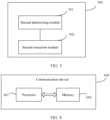
- FIG. 5 shows a schematic structural diagram of another transmission control apparatus according to an embodiment of this application.
- the apparatus 500 mainly includes: a second determining module 501 and a second execution module 502.
- the second determining module 501 is configured to determine a third status, or the third status and a fourth status; and the second execution module 502 is configured to, based on the third status or based on the third status and the fourth status, perform a second operation related to discontinuous reception DRX; where the third status includes: a status of a reporting resource; and the fourth status includes at least one of the following: a status of a sidelink feedback resource and a feedback enablement status.
- the third status includes at least one of the following that:
- the status of the sidelink feedback resource includes at least one of the following that:
- the feedback enablement status includes at least one of the following that: feedback is enabled and feedback is disabled.
- that the second execution module 502 performs the second operation based on the third status and the fourth status includes: performing, for the network side device, the second operation in a case that the third status is a fifth sub-status and the fourth status is a sixth sub-status, where the second operation includes one of the following:
- that the second execution module 502 performs the second operation includes:
- that the second execution module 502 performs the second operation based on the third status and the fourth status includes:
- the fifth sub-status includes one of the following that:
- the seventh sub-status includes at least one of the following:
- that the second execution module 502 performs the second operation includes:
- the first target time includes at least one of the following:
- the reporting resource having met the first condition includes at least one of the following that:
- the sidelink feedback resource meeting a second condition includes at least one of the following that:
- that the second execution module 502 performs the second operation based on the third status and the fourth status includes:
- that the second execution module 502 performs the second operation includes:
- the second target time includes at least one of the following:
- a reporting resource being configured or a reporting resource being scheduled includes at least one of the following that:
- the target control information includes: target downlink control information DCI and/or target sidelink control information SCI.
- the target DCI includes at least one of the following: sidelink DCI and Uu DCI.
- the network side device does not need to transmit control signaling and/or data during running of the first timer; and/or the first timer is a hybrid automatic repeat request HARQ RTT timer.
- the network side device transmits control signaling and/or data during running of the second timer; and/or the second timer is a retransmission timer.
- the transmission control apparatus in this embodiment of this application may be an apparatus, or may be a component, an integrated circuit, or a chip in a network side device.
- the network side device may include but is not limited to an eNB, a gNB, a roadside unit, a terminal with a scheduling or control capability, a header (header) terminal, or the like, which is not specifically limited in the embodiments of this application.
- the transmission control apparatus in this embodiment of this application may be an apparatus with an operating system.
- the operating system may be an Android (Android) operating system, an iOS operating system, or other possible operating systems, and is not specifically limited in the embodiments of this application.
- the transmission control apparatus provided in this embodiment of this application can implement the processes implemented in the method embodiment in FIG. 3 , with the same technical effects achieved. To avoid repetition, details are not described herein again.
- an embodiment of this application further provides a communication device 600, including a processor 601, a memory 602, and a program or instructions stored in the memory 602 and executable on the processor 601.
- a communication device 600 including a processor 601, a memory 602, and a program or instructions stored in the memory 602 and executable on the processor 601.
- the communication device 600 is a terminal and when the program or instructions are executed by the processor 601, the processes of the foregoing embodiment of the transmission control method 200 are implemented, with the same technical effects achieved.
- the communication device 600 is a network side device and when the program or instructions are executed by the processor 601, the processes of the foregoing embodiment of the transmission control method 300 are implemented, with the same technical effects achieved. To avoid repetition, details are not described herein again.
- An embodiment of this application further provides a terminal, including a processor and a communication interface, where the processor is configured to perform, based on a first status or based on the first status and a second status, a first operation related to discontinuous reception DRX; where the first status includes: a status of a reporting resource; and the second status includes at least one of the following: a status of a sidelink feedback resource and a feedback enablement status.
- the communication interface is configured to communicate with an external communication device.
- the communication interface may include a PCS interface, and sidelink communication may be performed with other terminals through the interface.
- the communication interface may include a Uu interface, and communication may be performed with a network side device through the Uu interface.
- FIG. 7 is a schematic diagram of a hardware structure of a terminal for implementing the embodiments of this application.
- the terminal 700 includes but is not limited to components such as a radio frequency unit 701, a network module 702, an audio output unit 703, an input unit 704, a sensor 705, a display unit 706, a user input unit 707, an interface unit 708, a memory 709, and a processor 710.
- the terminal 700 may further include a power supply (for example, a battery) supplying power to the components, and the power supply may be logically connected to the processor 710 through a power management system. In this way, functions such as charge management, discharge management, and power consumption management are implemented by using the power management system.
- a power supply for example, a battery
- functions such as charge management, discharge management, and power consumption management are implemented by using the power management system.
- the structure of the terminal shown in FIG. 7 does not constitute any limitation on the terminal.
- the terminal may include more or fewer components than shown in the figure, or a combination of some components, or the components disposed differently. Details are not described herein again.
- the input unit 704 may include a graphics processing unit (Graphics Processing Unit, GPU) 7041 and a microphone 7042.
- the graphics processing unit 7041 processes image data of a still picture or video obtained by an image capture apparatus (such as a camera) in a video capture mode or an image capture mode.
- the display unit 706 may include a display panel 7061, and the display panel 7061 may be configured in a form of a liquid crystal display, an organic light-emitting diode, and the like.
- the user input unit 707 may include a touch panel 7071 and other input devices 7072.
- the touch panel 7071 is also referred to as a touchscreen.
- the touch panel 7071 may include two parts: a touch detection apparatus and a touch controller.
- the other input devices 7072 may include but are not limited to a physical keyboard, a function key (such as a volume control key or a power on/off key), a trackball, a mouse, a joystick, and the like. Details are not described herein.
- the radio frequency unit 701 receives downlink data from a network side device, and then sends the downlink data to the processor 710 for processing; and also sends uplink data to the network side device.
- the radio frequency unit 701 includes but is not limited to an antenna, at least one amplifier, a transceiver, a coupler, a low noise amplifier, a duplexer, and the like.
- the memory 709 may be configured to store software programs or instructions and various data.
- the memory 709 may include a program or instruction storage area and a data storage area.
- the program or instruction storage area may store an operating system, an application program or instruction required by at least one function (for example, a sound playback function or an image playback function), and the like.
- the memory 709 may include a high-speed random access memory, and may further include a non-transitory memory.
- the non- transitory memory may be a read-only memory (Read-Only memory, ROM), a programmable read-only memory (Programmable ROM, PROM), an erasable programmable read-only memory (Erasable PROM, EPROM), an electrically erasable programmable read-only memory (Electrically EPROM, EEPROM), or a flash memory, for example, at least one disk storage device, a flash memory device, or another non-transitory solid-state storage device.
- ROM Read-Only memory
- PROM programmable read-only memory
- Erasable PROM Erasable PROM
- EPROM electrically erasable programmable read-only memory
- EEPROM electrically erasable programmable read-only memory
- flash memory for example, at least one disk storage device, a flash memory device, or another non-transitory solid-state storage device.
- the processor 710 may include one or more processing units.
- an application processor and a modem processor may be integrated in the processor 710.
- the application processor primarily processes an operating system, user interfaces, application programs or instructions, and the like.
- the modem processor primarily processes radio communication, for example, being a baseband processor. It can be understood that the modem processor may alternatively be not integrated in the processor 710.
- the processor 710 is configured to perform a first operation based on a first status or based on the first status and a second status.
- the first operation is an operation related to discontinuous reception DRX.
- the first status includes: a status of a reporting resource; and the second status includes at least one of the following: a status of a sidelink feedback resource and a feedback enablement status.
- the terminal performs the first operation based on the first status or based on the first status and the second status, where the first status includes: a status of a reporting resource; and the second status includes at least one of the following: a status of a sidelink feedback resource and a feedback enablement status.
- a DRX-related operation can be determined based on the status of the reporting resource, the status of the sidelink feedback resource, or the feedback enablement status, thereby implementing a DRX mechanism in sidelink.
- An embodiment of this application further provides a network side device, including a processor and a communication interface, where the processor is configured to perform a second operation based on a third status or based on the third status and a fourth status, where the third status includes: a status of a reporting resource; and the fourth status includes at least one of the following: a status of a sidelink feedback resource and a feedback enablement status; and the communication interface is configured to communicate with an external communication device (for example, the terminal).
- the network side device embodiments correspond to the embodiments of the foregoing network side device method 300, and the implementation processes and implementations of the foregoing method embodiments can be applied to the network side device embodiments, with the same technical effects achieved.
- the network side device 800 includes an antenna 801, a radio frequency apparatus 802, and a baseband apparatus 803.
- the antenna 801 is connected to the radio frequency apparatus 802.
- the radio frequency apparatus 802 receives information by using the antenna 801, and sends the received information to the baseband apparatus 803 for processing.
- the baseband apparatus 803 processes to-be-sent information, and sends the information to the radio frequency apparatus 802; and the radio frequency apparatus 802 processes the received information and then sends the information out by using the antenna 801.
- the frequency band processing apparatus may be located in the baseband apparatus 803.
- the method performed by the network side device in the foregoing embodiments may be implemented in the baseband apparatus 803, and the baseband apparatus 803 includes a processor 804 and a memory 805.
- the baseband apparatus 803 may include, for example, at least one baseband board, where a plurality of chips are disposed on the baseband board. As shown in FIG. 8 , one of the chips, for example, the processor 804, is connected to the memory 805, to invoke a program in the memory 805 to perform the operation of the network device shown in the foregoing method embodiments.
- the baseband apparatus 803 may further include a network interface 806, configured to exchange information with the radio frequency apparatus 802, where the interface is, for example, a common public radio interface (common public radio interface, CPRI for short).
- a network interface 806 configured to exchange information with the radio frequency apparatus 802, where the interface is, for example, a common public radio interface (common public radio interface, CPRI for short).
- the network side device in this embodiment of the present invention further includes: instructions or a program stored in the memory 805 and executable on the processor 804.
- the processor 804 invokes the instructions or program in the memory 805 to execute the method executed by the modules shown in FIG. 5 , with the same technical effects achieved. To avoid repetition, details are not repeated herein.
- An embodiment of this application further provides a readable storage medium, where a program or instructions are stored in the readable storage medium.
- a program or instructions are stored in the readable storage medium.
- the processor is a processor in the terminal described in the foregoing embodiments, or a processor in the network side device described in the foregoing embodiments.
- the readable storage medium includes a computer-readable storage medium, for example, a computer read-only memory (Read-Only Memory, ROM), a random access memory (Random Access Memory, RAM), a magnetic disk, or an optical disc.
- An embodiment of this application further provides a chip, where the chip includes a processor and a communications interface.
- the communications interface is coupled to the processor, and the processor is configured to run a program or instructions to implement the processes of the foregoing embodiments of the transmission control method 200 or the transmission control method 300, with the same technical effects achieved. To avoid repetition, details are not described herein again.
- the chip mentioned in the embodiments of this application may also be referred to as a system-level chip, a system chip, a chip system, a system-on-chip, or the like.
- An embodiment of this application provides a computer program/program product, where the computer program/program product is stored in a non-transitory storage medium, and when being executed by at least one processor, the program/program product is configured to implement the processes of the foregoing embodiments of the transmission control method 200 or the transmission control method 300, with the same technical effects achieved. To avoid repetition, details are not repeated herein.
- the computer software product is stored in a storage medium (such as a ROM/RAM, a magnetic disk, or an optical disc), and includes several instructions for instructing a terminal (which may be a mobile phone, a computer, a server, an air conditioner, a network device, or the like) to perform the methods described in the embodiments of this application.
- a storage medium such as a ROM/RAM, a magnetic disk, or an optical disc
- a terminal which may be a mobile phone, a computer, a server, an air conditioner, a network device, or the like
Landscapes
- Engineering & Computer Science (AREA)
- Computer Networks & Wireless Communication (AREA)
- Signal Processing (AREA)
- Mobile Radio Communication Systems (AREA)
Applications Claiming Priority (2)
| Application Number | Priority Date | Filing Date | Title |
|---|---|---|---|
| CN202110421166.0A CN115226215A (zh) | 2021-04-19 | 2021-04-19 | 传输控制方法、终端及网络侧设备 |
| PCT/CN2022/086534 WO2022222814A1 (fr) | 2021-04-19 | 2022-04-13 | Procédé de commande de transmission, terminal et dispositif côté réseau |
Publications (2)
| Publication Number | Publication Date |
|---|---|
| EP4329403A1 true EP4329403A1 (fr) | 2024-02-28 |
| EP4329403A4 EP4329403A4 (fr) | 2024-12-11 |
Family
ID=83605711
Family Applications (1)
| Application Number | Title | Priority Date | Filing Date |
|---|---|---|---|
| EP22790922.3A Pending EP4329403A4 (fr) | 2021-04-19 | 2022-04-13 | Procédé de commande de transmission, terminal et dispositif côté réseau |
Country Status (4)
| Country | Link |
|---|---|
| US (1) | US20240049346A1 (fr) |
| EP (1) | EP4329403A4 (fr) |
| CN (1) | CN115226215A (fr) |
| WO (1) | WO2022222814A1 (fr) |
Families Citing this family (1)
| Publication number | Priority date | Publication date | Assignee | Title |
|---|---|---|---|---|
| US20240205912A1 (en) * | 2022-12-20 | 2024-06-20 | Qualcomm Incorporated | Sidelink feedback for network energy savings |
Family Cites Families (12)
| Publication number | Priority date | Publication date | Assignee | Title |
|---|---|---|---|---|
| CN110890943B (zh) * | 2018-09-07 | 2022-02-08 | 维沃移动通信有限公司 | 确定方法、终端设备及网络设备 |
| WO2020068973A1 (fr) * | 2018-09-25 | 2020-04-02 | Idac Holdings, Inc. | Procédés, dispositifs et systèmes de support de l'harq sur v2x |
| US11432358B2 (en) * | 2019-03-28 | 2022-08-30 | Lg Electronics Inc. | Operation method of sidelink TX UE for transmitting Rrc message related to RLF after RRC resumption in wireless communication system |
| KR102874285B1 (ko) * | 2019-07-04 | 2025-10-22 | 엘지전자 주식회사 | 무선통신시스템에서 사이드링크 drx에 관련된 ue의 동작 방법 |
| WO2021067583A2 (fr) * | 2019-10-01 | 2021-04-08 | Ofinno, Llc | Utilisation d'une liaison latérale dans le cadre d'une nouvelle radio (nr) |
| CN114762279B (zh) * | 2019-10-06 | 2023-12-12 | Lg电子株式会社 | 在nr v2x中用于向基站报告harq反馈的方法和装置 |
| MX2022005586A (es) * | 2019-11-06 | 2022-10-27 | Lenovo Singapore Pte Ltd | Determinación de un recurso para un informe de información de estado del canal. |
| CN110945962B (zh) * | 2019-11-12 | 2022-04-15 | 北京小米移动软件有限公司 | 非连续接收的参数配置方法、装置、终端及存储介质 |
| EP4091277A1 (fr) * | 2020-01-16 | 2022-11-23 | Lenovo (Singapore) Pte. Ltd. | Retransmission d'un bloc de transport ayant une rétroaction de liaison latérale désactivée |
| WO2021203248A1 (fr) * | 2020-04-07 | 2021-10-14 | 北京小米移动软件有限公司 | Procédé et dispositif de réglage d'heure d'activation et support d'enregistrement lisible par ordinateur |
| CN115150974B (zh) * | 2021-03-29 | 2024-12-17 | 大唐移动通信设备有限公司 | 直接通信接口drx和/或dtx状态维护方法及直接通信终端 |
| JP7643585B2 (ja) * | 2021-03-31 | 2025-03-11 | 富士通株式会社 | データ送信方法、装置及びシステム |
-
2021
- 2021-04-19 CN CN202110421166.0A patent/CN115226215A/zh active Pending
-
2022
- 2022-04-13 EP EP22790922.3A patent/EP4329403A4/fr active Pending
- 2022-04-13 WO PCT/CN2022/086534 patent/WO2022222814A1/fr not_active Ceased
-
2023
- 2023-10-18 US US18/381,609 patent/US20240049346A1/en active Pending
Also Published As
| Publication number | Publication date |
|---|---|
| US20240049346A1 (en) | 2024-02-08 |
| CN115226215A (zh) | 2022-10-21 |
| EP4329403A4 (fr) | 2024-12-11 |
| WO2022222814A1 (fr) | 2022-10-27 |
Similar Documents
| Publication | Publication Date | Title |
|---|---|---|
| US20230247553A1 (en) | DRX Determining Method and Apparatus, Terminal, and Readable Storage Medium | |
| US12096362B2 (en) | Communication method and apparatus | |
| US20230208563A1 (en) | Discontinuous reception control method and apparatus, terminal, and readable storage medium | |
| US20110003555A1 (en) | Method and Apparatus for PDCCH Monitoring | |
| US20230300743A1 (en) | Indication information validation method and apparatus, terminal, and readable storage medium | |
| US20230164876A1 (en) | Discontinuous Reception Processing Method and Apparatus, Terminal, and Network-Side Device | |
| WO2022151247A1 (fr) | Réception discontinue de liaison latérale au niveau d'un équipement utilisateur | |
| US20230189276A1 (en) | Uplink transmission method and device, and readable storage medium | |
| US20230363050A1 (en) | Transmission configuration method and apparatus and related device | |
| US20240057000A1 (en) | Synchronization resource configuration method and apparatus, user equipment, and storage medium | |
| US20240049346A1 (en) | Transmission control method, terminal, and network-side device | |
| US20250358895A1 (en) | Transmission processing method, transmission processing apparatus, terminal, and network-side device | |
| US20250254747A1 (en) | Processing method and apparatus for consistent listen before talk (lbt) failure, and user equipment and storage medium | |
| US20230422342A1 (en) | Sidelink Discontinuous Reception Configuration Method, Device, and Non-transitory Computer-Readable Storage Medium | |
| CN119697811A (zh) | Pdcch监听控制方法、装置、终端、网络侧设备及介质 | |
| CN115022847B (zh) | Sl csi报告的处理方法、装置及设备 | |
| EP4294061A1 (fr) | Procédé et appareil de commande de temporisateur, et terminal | |
| US20240008142A1 (en) | Discontinuous Reception Method and Apparatus, and Terminal | |
| US20240107618A1 (en) | Information transmission method and apparatus, and storage medium | |
| EP4716130A1 (fr) | Procédé et appareil de rétroaction de requête automatique de répétition hybride (harq), et terminal | |
| CN115915094B (zh) | 辅小区组状态控制方法、装置、网元及终端 | |
| US20250119929A1 (en) | Method and apparatus for processing sidelink transmission in unlicensed band, and related device | |
| WO2023131304A1 (fr) | Procédé et appareil de sélection de ressource de liaison latérale | |
| WO2024012236A1 (fr) | Procédé et appareil de traitement de rétroaction de liaison latérale, terminal et dispositif côté réseau | |
| WO2024012302A1 (fr) | Procédé de traitement de rétroaction de liaison latérale, appareil, terminal et dispositif côté réseau |
Legal Events
| Date | Code | Title | Description |
|---|---|---|---|
| STAA | Information on the status of an ep patent application or granted ep patent |
Free format text: STATUS: THE INTERNATIONAL PUBLICATION HAS BEEN MADE |
|
| PUAI | Public reference made under article 153(3) epc to a published international application that has entered the european phase |
Free format text: ORIGINAL CODE: 0009012 |
|
| STAA | Information on the status of an ep patent application or granted ep patent |
Free format text: STATUS: REQUEST FOR EXAMINATION WAS MADE |
|
| 17P | Request for examination filed |
Effective date: 20231115 |
|
| AK | Designated contracting states |
Kind code of ref document: A1 Designated state(s): AL AT BE BG CH CY CZ DE DK EE ES FI FR GB GR HR HU IE IS IT LI LT LU LV MC MK MT NL NO PL PT RO RS SE SI SK SM TR |
|
| DAV | Request for validation of the european patent (deleted) | ||
| DAX | Request for extension of the european patent (deleted) | ||
| A4 | Supplementary search report drawn up and despatched |
Effective date: 20241111 |
|
| RIC1 | Information provided on ipc code assigned before grant |
Ipc: H04W 92/18 20090101ALI20241105BHEP Ipc: H04L 1/1829 20230101ALI20241105BHEP Ipc: H04W 52/02 20090101ALI20241105BHEP Ipc: H04W 76/28 20180101ALI20241105BHEP Ipc: H04W 72/04 20230101AFI20241105BHEP |