EP4329435B1 - Verfahren mit austauschbaren ionenstrahlzielen - Google Patents
Verfahren mit austauschbaren ionenstrahlzielen Download PDFInfo
- Publication number
- EP4329435B1 EP4329435B1 EP23220718.3A EP23220718A EP4329435B1 EP 4329435 B1 EP4329435 B1 EP 4329435B1 EP 23220718 A EP23220718 A EP 23220718A EP 4329435 B1 EP4329435 B1 EP 4329435B1
- Authority
- EP
- European Patent Office
- Prior art keywords
- ion beam
- target
- targets
- neutron energy
- accelerator
- Prior art date
- Legal status (The legal status is an assumption and is not a legal conclusion. Google has not performed a legal analysis and makes no representation as to the accuracy of the status listed.)
- Active
Links
Images


Classifications
-
- G—PHYSICS
- G21—NUCLEAR PHYSICS; NUCLEAR ENGINEERING
- G21G—CONVERSION OF CHEMICAL ELEMENTS; RADIOACTIVE SOURCES
- G21G4/00—Radioactive sources
- G21G4/02—Neutron sources
-
- G—PHYSICS
- G01—MEASURING; TESTING
- G01N—INVESTIGATING OR ANALYSING MATERIALS BY DETERMINING THEIR CHEMICAL OR PHYSICAL PROPERTIES
- G01N23/00—Investigating or analysing materials by the use of wave or particle radiation, e.g. X-rays or neutrons, not covered by groups G01N3/00 – G01N17/00, G01N21/00 or G01N22/00
- G01N23/02—Investigating or analysing materials by the use of wave or particle radiation, e.g. X-rays or neutrons, not covered by groups G01N3/00 – G01N17/00, G01N21/00 or G01N22/00 by transmitting the radiation through the material
- G01N23/025—Investigating or analysing materials by the use of wave or particle radiation, e.g. X-rays or neutrons, not covered by groups G01N3/00 – G01N17/00, G01N21/00 or G01N22/00 by transmitting the radiation through the material using neutrons
-
- G—PHYSICS
- G01—MEASURING; TESTING
- G01T—MEASUREMENT OF NUCLEAR OR X-RADIATION
- G01T1/00—Measuring X-radiation, gamma radiation, corpuscular radiation, or cosmic radiation
- G01T1/02—Dosimeters
- G01T1/12—Calorimetric dosimeters
-
- G—PHYSICS
- G21—NUCLEAR PHYSICS; NUCLEAR ENGINEERING
- G21K—HANDLING OF PARTICLES OR IONISING RADIATION NOT OTHERWISE PROVIDED FOR; IRRADIATION DEVICES; GAMMA RAY OR X-RAY MICROSCOPES
- G21K1/00—Arrangements for handling particles or ionising radiation, e.g. focusing or moderating
- G21K1/02—Arrangements for handling particles or ionising radiation, e.g. focusing or moderating using diaphragms, collimators
-
- H—ELECTRICITY
- H05—ELECTRIC TECHNIQUES NOT OTHERWISE PROVIDED FOR
- H05H—PLASMA TECHNIQUE; PRODUCTION OF ACCELERATED ELECTRICALLY-CHARGED PARTICLES OR OF NEUTRONS; PRODUCTION OR ACCELERATION OF NEUTRAL MOLECULAR OR ATOMIC BEAMS
- H05H3/00—Production or acceleration of neutral particle beams, e.g. molecular or atomic beams
- H05H3/06—Generating neutron beams
Definitions
- each of the plurality of ion beam targets is configured to generate a monoenergetic energy value that is at least 100 kiloelectron volts (keV) different from the other ion beam targets.
- the ion beam targets are composed of LiF, TiD 1.5-1.8 , TiT 1-2 , ErD 1.5 , ErT, or Li.
- Neutron radiography and tomography are proven techniques for the nondestructive testing and quality control of manufactured components in the aerospace, energy, automotive, defense, and other sectors. Like X-rays, when neutrons pass through an object, they provide information about the internal structure of that object. Neutrons are able to easily pass through many high density materials and provide detailed information about internal materials, including many low density materials. This property is extremely important for a number of components that require nondestructive evaluation including jet engine turbine blades, satellite components, munitions, aircraft and spacecraft components, and composite materials.
- US 5870447 discloses a particle accelerator that generates an input particle beam having an initial energy level above a threshold for generating secondary nuclear particles.
- a thin target is rotated in the path of the input beam for undergoing nuclear reactions to generate the secondary particles and correspondingly decrease energy of the input beam to about the threshold.
- the target produces low energy secondary particles and is effectively cooled by radiation and conduction.
- a neutron scatterer and a neutron filter are also used for preferentially degrading the secondary particles into a lower energy range if desired.
- each of the plurality of ion beam targets is configured to generate a monoenergetic energy value that is at least 100 kiloelectron volts (keV) different from the other ion beam targets.
- the ion beam targets are composed of LiF, TiD 1.5-1.8 , TiT 1-2 , ErD 1.5 , ErT, or Li.
- Also provided herein are systems for generating a plurality of monoenergetic neutron energies comprising: a) an ion source configured to produce an ion beam; b) an accelerator operatively coupled to the ion source and configured to receive the ion beam and accelerate the ion beam to generate an accelerated ion beam; c) a target station comprising a target holding mechanism; and d) a plurality of interchangeable ion beam targets, wherein each of the interchangeable ion beam targets: i) is configured to be held by the target holding mechanism, and ii) generates neutrons with a monoenergetic neutron energy value unique among the plurality of interchangeable ion beam targets when struck with the accelerated ion beam, and wherein collectively the plurality of interchangeable ion beam targets, when struck with the accelerated ion beam, provide neutrons with a range of monoenergetic neutron energy values that spans at least 300 kiloelectron volts (keV) (or
- each of interchangeable the ion beam targets comprises, consists of, or consists essentially of: LiF, TiD 1.5-1.8 , TiT 1-2 , ErD 1.5 , ErT, and/or Li.
- each of the interchangeable ion beam targets: iii) has a thickness unique among the plurality of ion beam targets.
- collectively the plurality of interchangeable ion beam targets provide neutrons with a range of monoenergetic neutron energy values that spans at least one mega-electron-volt (MeV) (e.g., at least 1 ... 1.5 ... 2.0 ... 4.5 ... 7.0 ... or 9.0 MeV).
- MeV mega-electron-volt
- the plurality of interchangeable ion beam targets provide neutrons with a range of monoenergetic neutron energy values that spans at least ten mega-electron-volts (e.g., at least 10 ... 12 ... 15 ... or 20 mega-electron volts).
- the monoenergetic neutron energy of each of the plurality of interchangeable ion beam targets is at least 100 keV different from each other (e.g., at least 100 ... 200 ... 400 ... 800 ... or 2000 keV). In further embodiments, the monoenergetic neutron energy of each of the plurality of interchangeable ion beam targets is at least 500 keV different from each other. In some embodiments, the plurality of interchangeable ion beam targets comprises at least three ion beam targets (e.g., at least 3, 4, 5, 6, 7, 8, or 9). In other embodiments, the plurality of interchangeable ion beam targets comprises at least six ion beam targets (e.g., at least 6, 7, 8, 9, 10, 11, 12, 13, 14, or 15).
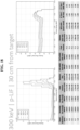
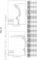
- the plurality of interchangeable ion beam targets comprises: i) a first ion beam target that generates a monoenergetic neutron energy value of about 300 keV; ii) a second ion beam target that generates a monoenergetic neutron energy value of about 1 MeV; iii) a third ion beam target that generates a monoenergetic neutron energy value of about 2.5 MeV; iv) a fourth ion beam target that generates a monoenergetic neutron energy value of about 4 MeV; v) a fifth ion beam target that generates a monoenergetic neutron energy value of about 6 MeV; and vi) a sixth ion beam target that generates a monoenergetic neutron energy value of about 14 MeV.
- monoenergetic neutron energy values between the previously recited values are employed (e.g., 700 keV, 2.3 MeV, 3.1 MeV, 5.2 MeV, and 12.3 Me
- the systems further comprise a control system, wherein the control system comprises software configured to alter the incoming ion energy of the accelerated ion beam based on which of the plurality of plurality of interchangeable ion beam targets are held by the target holding mechanism.
- the systems further comprise a testing facility configured to scan an item with the neutrons.
- the item is selected from the group consisting of: a space system, space equipment, airplane component, infrastructure, and a component of a transportation system.
- the systems further comprise a collimator.
- the target station further comprises a water cooling system.
- methods comprising: a) inserting a first target, from a set of at least two ion beam targets, into an ion beam accelerator that generates an accelerated ion beam; b) activating the ion beam accelerator for a length of time such than an accelerated ion beam strikes the first target, thereby generating neutrons with a first monoenergetic neutron energy value; c) removing the first target from the ion beam accelerator; d) inserting a second target, from the set of at least two targets, into the ion beam accelerator; and e) activating the ion beam accelerator for a length of time (and at a certain energy) such than an ion beam strikes the second target, thereby generating neutrons with a second monoenergetic neutron energy value that is at least 100 kiloelectron volts (keV) different from the first monoenergetic neutron energy value.
- keV kiloelectron volts
- the second monoenergetic neutron energy value is at last 500 kiloelectron volts (keV) different from the first monoenergetic neutron energy value (e.g., at least 500 ... 1000 ... 2000 ... 10,000 keV).
- the at least two ion beam targets comprise at least three ion beam targets
- the method further comprises: f) removing the second target from the ion beam accelerator; g) inserting a third target, from the set of at least three targets, into the ion beam accelerator; and h) activating the ion beam accelerator for a length of time such than an ion beam strikes the third target, thereby generating neutrons with a third monoenergetic neutron energy value that is at least 100 kiloelectron volts (keV) different from both the first and second monoenergetic neutron energy values.
- the third monoenergetic neutron energy value is at last 500 kiloelectron volts different from the first and second monoenergetic neutron energy values.
- the at least three ion beam targets comprises at least four ion beam targets
- the method further comprises: i) removing the third target from the ion beam accelerator; j) inserting a fourth target, from the set of at least four targets, into the ion beam accelerator; and k) activating the ion beam accelerator for a length of time such than an ion beam strikes the fourth target, thereby generating neutrons with a fourth monoenergetic neutron energy value that is at least 100 kiloelectron volts (keV) different from all of the first, second, and third monoenergetic neutron energy values.
- keV kiloelectron volts
- the fourth monoenergetic neutron energy value is at last 500 kiloelectron volts different from the first, second, and third monoenergetic neutron energy values. In some embodiments, the steps are repeated for a fifth, sixth, seventh or more ion beam target.
- each of the ion beam targets comprises, consists of, or consists essentially of: LiF, TiD 1.5-1.8 , TiT 1-2 , ErD 1.5 , ErT, or Li.
- each of the at least four ion beam targets has a thickness unique among the first, second, third, and fourth ion beam targets.
- collectively the at least four ion beam targets provide neutrons with a range of monoenergetic neutron energy values that spans at least five or 10 mega-electron-volts (MeV) (e.g., at least 5 ... 7 ... 10 ... 15 ... 20 ... or 30 MeV).
- MeV mega-electron-volts
- the methods further comprise a step between b) and c) (or between g) and h), or between j) and k)) of using the neutrons with a first monoenergetic neutron energy value to scan an item.
- the item is selected from the group consisting of: a space system, space equipment, airplane component, infrastructure, and a component of a transportation system.
- the each of the at least two, or at least three, or at least four ion beam targets generate a different monoenergetic neutron energy value selected from the group consisting of: of about 300 keV, about 1 MeV, about 2.5 MeV, about 4 MeV, about 6 MeV, and about 14 MeV.
- Also provided herein are systems comprising: a) a computer processor; b) non-transitory computer memory comprising one or more computer programs and a database, wherein said one or more computer programs comprises accelerator system operating software; and c) an ion beam accelerator system comprising one or more of the following sub-systems which are in operable communication with said non-transitory computer memory, and which can be automatically adjusted by said accelerator system operating software to account for a particular ion beam target present in said ion beam accelerator system selected from a plurality of ion beam targets: i) a target station comprising a target holding mechanism configured to hold one of said plurality of said ion beam targets; and ii) a beam generating sub-system that generates an ion beam with a strength adjusted by said accelerator system operating software based on which of said plurality of ion beam targets is present in said ion beam accelerator system.
- each of the plurality of ion beam targets is configured to generate a monoenergetic energy value that is at least 100 kiloelectron volts (keV) different from the other ion beam targets.
- the ion beam targets are composed of: LiF, TiD 1.5-1.8 , TiT 1-2 , ErD 1.5 , ErT, or Li.
- systems and parts are scanned for radiation and/or internal defects including, but not limited to: space systems and equipment (e.g., satellite and satellite components), materials and components subjected to possible radiation damage, materials and components subjected to possible radiation damage, functional/electronic systems used in civil nuclear plants (e.g., equipment nuclearization), infrastructures (e.g., hardening with respect to lightning), systems that might be sensitive to the natural radiation environment (e.g., atmospheric neutrons) particularly as related to reliability (e.g. transportation means), and systems that need to handle threats from directed energy weapons (e.g., High Power Microwaves).
- space systems and equipment e.g., satellite and satellite components
- materials and components subjected to possible radiation damage materials and components subjected to possible radiation damage
- functional/electronic systems used in civil nuclear plants e.g., equipment nuclearization
- infrastructures e.g.
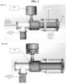
- the systems and methods herein employ a target station that allow different targets to be installed therein.
- An exemplary target station is shown in Figure 3 attached to a portion of an accelerator system.
- the beam when not irradiating a target, the beam will encounter a beam dump controlled by an air actuated linear feedthrough as shown in Figure 4A (e.g., 100% of the beam is collected into the Beam Dump and current is measured).
- the Beam Dump is able to retract and allow the beam to continue (e.g., to the four finger collimator as shown in Figure 4B ).
- the target station design employs one beamline impinging on a single target to produce the desired reaction.
- the target can be swapped out with other targets for different reactions.
- the procedure for changing employs the following steps: 1) Close a standard gate valve between the target and a fast valve that isolates the pumping station from the target area; 2) Vent the target area; 3) Remove the back target flange, the 4-finger collimator remains in place unless it is being serviced; 4) Remove the target by loosening two VCR-type nuts that attach the water-cooling lines or by removing the target disk; 5) Install new target into the back flange by tightening two VCR-type nuts; 6) Reinstall the back target flange onto the 4-finger collimator flange; 7) Open Valve to roughing pump, rough target chamber, close the valve to rough pump; and 8) Open a gate valve to the pumping stage (interlocked can only be performed when adequate pressure is achieved, and the rough pump valve is closed).
Landscapes
- Physics & Mathematics (AREA)
- High Energy & Nuclear Physics (AREA)
- Spectroscopy & Molecular Physics (AREA)
- Engineering & Computer Science (AREA)
- Chemical & Material Sciences (AREA)
- General Engineering & Computer Science (AREA)
- Health & Medical Sciences (AREA)
- Life Sciences & Earth Sciences (AREA)
- General Physics & Mathematics (AREA)
- Chemical Kinetics & Catalysis (AREA)
- General Chemical & Material Sciences (AREA)
- Plasma & Fusion (AREA)
- General Health & Medical Sciences (AREA)
- Pathology (AREA)
- Immunology (AREA)
- Biochemistry (AREA)
- Analytical Chemistry (AREA)
- Molecular Biology (AREA)
- Particle Accelerators (AREA)
- Analysing Materials By The Use Of Radiation (AREA)
- Optics & Photonics (AREA)
Claims (15)
- Verfahren, umfassend:Einführen eines ersten Ziels aus einem Satz von mindestens zwei Ionenstrahlzielen in einen Ionenstrahlbeschleuniger (30), der einen beschleunigten Ionenstrahl erzeugt;Aktivieren des Ionenstrahlbeschleunigers (30) für eine Zeitdauer, sodass ein beschleunigter Ionenstrahl auf das erste Ziel trifft, wodurch Neutronen mit einem ersten monoenergetischen Neutronenenergiewert erzeugt werden;Entfernen des ersten Ziels aus dem Ionenstrahlbeschleuniger (30); das Verfahren dadurch gekennzeichnet, dass es ferner Folgendes umfasst:Einführen eines zweiten Ziels aus dem Satz von mindestens zwei Zielen in den Ionenstrahlbeschleuniger (30); undAktivieren des Ionenstrahlbeschleunigers (30) für eine Zeitdauer, sodass ein Ionenstrahl auf das zweite Ziel trifft, wodurch Neutronen mit einem zweiten monoenergetischen Neutronenenergiewert erzeugt werden, der sich mindestens um 100 Kiloelektronenvolt (keV) von dem ersten monoenergetischen Neutronenenergiewert unterscheidet.
- Verfahren nach Anspruch 1, wobei sich der zweite monoenergetische Neutronenenergiewert um mindestens 500 Kiloelektronenvolt von dem ersten monoenergetischen Neutronenenergiewert unterscheidet.
- Verfahren nach Anspruch 1, ferner umfassend einen Schritt des Verwendens der Neutronen mit dem ersten monoenergetischen Neutronenenergiewert zum Scannen eines Elements.
- Verfahren nach Anspruch 3, ferner umfassend einen Schritt des Verwendens der Neutronen mit dem zweiten monoenergetischen Neutronenenergiewert zum Scannen eines Elements.
- Verfahren nach Anspruch 3, wobei das Element aus der Gruppe ausgewählt ist, bestehend aus: einem Raumsystem, einer Raumausrüstung, einer Flugzeugkomponente, einer Infrastruktur, Materialien und Komponenten, die einer möglichen Strahlungsbeschädigung ausgesetzt sind, und einer Komponente eines Transportsystems.
- Verfahren nach Anspruch 1, wobei die mindestens zwei Ionenstrahlziele mindestens drei Ionenstrahlziele umfassen, und das Verfahren ferner Folgendes umfasst:Entfernen des zweiten Ziels aus dem Ionenstrahlbeschleuniger (30);Einführen eines dritten Ziels aus dem Satz von mindestens drei Zielen in den Ionenstrahlbeschleuniger (30); undAktivieren des Ionenstrahlbeschleunigers (30) für eine Zeitdauer, sodass ein Ionenstrahl auf das dritte Ziel trifft, wodurch Neutronen mit einem dritten monoenergetischen Neutronenenergiewert erzeugt werden, der sich mindestens um 100 Kiloelektronenvolt (keV) von sowohl den ersten als auch zweiten monoenergetischen Neutronenenergiewerten unterscheidet.
- Verfahren nach Anspruch 6, wobei sich der dritte monoenergetische Neutronenenergiewert um mindestens 500 Kiloelektronenvolt von den ersten und zweiten monoenergetischen Neutronenenergiewerten unterscheidet.
- Verfahren nach Anspruch 6, wobei die mindestens drei Ionenstrahlziele mindestens vier Ionenstrahlziele umfassen, und das Verfahren ferner Folgendes umfasst:Entfernen des dritten Ziels aus dem Ionenstrahlbeschleuniger (30);Einführen eines vierten Ziels aus dem Satz von mindestens vier Zielen in den Ionenstrahlbeschleuniger (30); undAktivieren des Ionenstrahlbeschleunigers (30) für eine Zeitdauer, sodass ein Ionenstrahl auf das vierte Ziel trifft, wodurch Neutronen mit einem vierten monoenergetischen Neutronenenergiewert erzeugt werden, der sich mindestens um 100 Kiloelektronenvolt (keV) von allen ersten, zweiten und dritten monoenergetischen Neutronenenergiewerten unterscheidet.
- Verfahren nach Anspruch 8, wobei sich der vierte monoenergetische Neutronenenergiewert um mindestens 500 Kiloelektronenvolt von den ersten, zweiten und dritten monoenergetischen Neutronenenergiewerten unterscheidet, und/oderwobei jedes der mindestens vier Ionenstrahlziele Folgendes umfasst, daraus besteht oder im Wesentlichen daraus besteht: LiF, TiD1.5-1.8, TiT1-2, ErD1.5, ErT, oder Li, und/oderwobei jedes der mindestens vier Ionenstrahlziele eine Dicke aufweist, die einzigartig unter den ersten, zweiten, dritten und vierten Ionenstrahlzielen ist.
- Verfahren nach Anspruch 1, ferner umfassend das Richten des Ionenstrahls auf einen Kollimator, der vier Finger aufweist.
- Verfahren nach Anspruch 10, wobei ein erster Abschnitt des Ionenstrahls auf den Kollimator trifft und ein zweiter Abschnitt des Ionenstrahls durch eine zentrale Öffnung des Kollimators hindurchgeht.
- Verfahren nach Anspruch 11, ferner umfassend das Messen eines Strahlstroms des ersten Abschnitts des Ionenstrahls unter Verwendung des Kollimators, und optional,
ferner umfassend das Bestimmen eines Strahlstroms des zweiten Abschnitts des Ionenstrahls. - Verfahren nach Anspruch 11, ferner umfassend, vor dem Richten des Ionenstrahls auf den Kollimator, das Richten des ersten Abschnitts und des zweiten Abschnitts des Ionenstrahls in einen Strahlenkanal, das Messen eines Gesamtstrahlstroms des Ionenstrahls unter Verwendung des Strahlenkanals und das Zurückziehen des Strahlenkanals weg von einem Weg des Ionenstrahls, und, optional, ferner umfassend das Bestimmen eines Strahlstroms des zweiten Abschnitts des Ionenstrahls unter Verwendung des Strahlstroms des ersten Abschnitts des Ionenstrahls, der unter Verwendung des Kollimators gemessen wurde, und des Gesamtstrahlstroms des Ionenstrahls, der unter Verwendung des Strahlenkanals gemessen wurde.
- Verfahren nach Anspruch 10, wobei die Vielzahl von Fingern kollektiv ein Ringraum bildet, der eine zentrale Öffnung aufweist, und wobei jede der Vielzahl von Fingern Folgendes umfasst:eine Protonensenke, die an einer inneren Umrandung des Ringraums radial benachbart zur zentralen Öffnung positioniert ist;einen Kühlkörper, der an einer äußeren Umrandung des Ringraums positioniert ist; undeinen isolierten Kühlkreislauf, wobei jeder jeweilige Kühlkreislauf voneinander isoliert und konfiguriert ist, eine Kalorimetrie durchzuführen.
- Verfahren nach Anspruch 14, wobei jede Protonensenke Tantal umfasst, oder wobei jeder Kühlkörper Kupfer umfasst.
Applications Claiming Priority (3)
| Application Number | Priority Date | Filing Date | Title |
|---|---|---|---|
| US201962869337P | 2019-07-01 | 2019-07-01 | |
| EP20834138.8A EP3994500B1 (de) | 2019-07-01 | 2020-06-29 | Systeme und verfahren mit einsatz von austauschbaren ionenstrahlzielen |
| PCT/US2020/040150 WO2021003107A2 (en) | 2019-07-01 | 2020-06-29 | Systems and methods employing interchangeable ion beam targets |
Related Parent Applications (2)
| Application Number | Title | Priority Date | Filing Date |
|---|---|---|---|
| EP20834138.8A Division-Into EP3994500B1 (de) | 2019-07-01 | 2020-06-29 | Systeme und verfahren mit einsatz von austauschbaren ionenstrahlzielen |
| EP20834138.8A Division EP3994500B1 (de) | 2019-07-01 | 2020-06-29 | Systeme und verfahren mit einsatz von austauschbaren ionenstrahlzielen |
Publications (3)
| Publication Number | Publication Date |
|---|---|
| EP4329435A2 EP4329435A2 (de) | 2024-02-28 |
| EP4329435A3 EP4329435A3 (de) | 2024-06-05 |
| EP4329435B1 true EP4329435B1 (de) | 2025-03-05 |
Family
ID=74101263
Family Applications (2)
| Application Number | Title | Priority Date | Filing Date |
|---|---|---|---|
| EP23220718.3A Active EP4329435B1 (de) | 2019-07-01 | 2020-06-29 | Verfahren mit austauschbaren ionenstrahlzielen |
| EP20834138.8A Active EP3994500B1 (de) | 2019-07-01 | 2020-06-29 | Systeme und verfahren mit einsatz von austauschbaren ionenstrahlzielen |
Family Applications After (1)
| Application Number | Title | Priority Date | Filing Date |
|---|---|---|---|
| EP20834138.8A Active EP3994500B1 (de) | 2019-07-01 | 2020-06-29 | Systeme und verfahren mit einsatz von austauschbaren ionenstrahlzielen |
Country Status (4)
| Country | Link |
|---|---|
| US (3) | US11610697B2 (de) |
| EP (2) | EP4329435B1 (de) |
| JP (3) | JP7542018B2 (de) |
| WO (1) | WO2021003107A2 (de) |
Families Citing this family (3)
| Publication number | Priority date | Publication date | Assignee | Title |
|---|---|---|---|---|
| EP4329435B1 (de) | 2019-07-01 | 2025-03-05 | SHINE Technologies, LLC | Verfahren mit austauschbaren ionenstrahlzielen |
| CN116156729A (zh) * | 2023-02-07 | 2023-05-23 | 中国原子能科学研究院 | 一种基于质子加速器的准单能中子靶及中子束流调节方法 |
| WO2025122731A1 (en) * | 2023-12-05 | 2025-06-12 | Shine Technologies, Llc | Multi-beam spallation source for intense neutron generation |
Family Cites Families (29)
| Publication number | Priority date | Publication date | Assignee | Title |
|---|---|---|---|---|
| US2769096A (en) * | 1952-04-09 | 1956-10-30 | Schlumberger Well Surv Corp | Multiple-target sources of radioactive radiations and methods employing the same |
| US3287592A (en) * | 1961-12-14 | 1966-11-22 | High Voltage Engineering Corp | Particle accelerator assembly having a beryllium-tritium composite target |
| US4818468A (en) * | 1977-08-03 | 1989-04-04 | The Regents Of The University Of California | Continuous flow radioactive production |
| US4666651A (en) * | 1982-04-08 | 1987-05-19 | Commissariat A L'energie Atomique | High energy neutron generator |
| JPS60222000A (ja) * | 1984-02-29 | 1985-11-06 | 工業技術院長 | 中性子線発生用タ−ゲツト装置およびその冷却方法 |
| JPS60183599A (ja) * | 1984-03-02 | 1985-09-19 | キヤノン株式会社 | X線コリメ−タ |
| JPH08279624A (ja) * | 1995-04-07 | 1996-10-22 | Rikagaku Kenkyusho | 放射光位置モニター |
| WO1997041422A1 (en) | 1996-04-30 | 1997-11-06 | Radio Programmes Corp. | Substance detection device using monoenergetic neutrons |
| US5870447A (en) * | 1996-12-30 | 1999-02-09 | Brookhaven Science Associates | Method and apparatus for generating low energy nuclear particles |
| US6144032A (en) | 1998-05-07 | 2000-11-07 | Gazdzinski; Robert F. | Method and apparatus for measuring the condition of degradable components |
| JP2000056098A (ja) | 1998-08-07 | 2000-02-25 | Mitsubishi Heavy Ind Ltd | 低エネルギー中性子照射装置 |
| EP1321948A1 (de) * | 2001-12-21 | 2003-06-25 | Ion Beam Applications S.A. | Verfahren und Vorrichtung zur Erzeugung von Radioisotopen aus einem Ziel |
| ATE409946T1 (de) * | 2002-05-21 | 2008-10-15 | Univ Duke | Rezirkulierendes target und verfahren zur herstellung eines radionuklids |
| EP1720173A1 (de) * | 2005-05-06 | 2006-11-08 | Deutsches Krebsforschungszentrum Stiftung des öffentlichen Rechts | Kollimator zum Begrenzen eines Bündels energiereicher Strahlen |
| EP1883281B1 (de) | 2006-07-28 | 2012-09-05 | Sage Innovations, Inc. | Ein Verfahren zur Erzeugung eines Impuls-Strahles von energiereichen Teilchen, und Teilchenquelle dazu |
| JP4649580B2 (ja) | 2006-09-26 | 2011-03-09 | 独立行政法人 日本原子力研究開発機構 | 複合型廃棄体確認システム |
| US7397901B1 (en) * | 2007-02-28 | 2008-07-08 | Varian Medical Systems Technologies, Inc. | Multi-leaf collimator with leaves formed of different materials |
| JP5178238B2 (ja) * | 2008-02-27 | 2013-04-10 | 住友重機械工業株式会社 | ターゲット回収装置 |
| WO2013133342A1 (ja) * | 2012-03-06 | 2013-09-12 | 独立行政法人理化学研究所 | 中性子発生源および中性子発生装置 |
| JP2014044098A (ja) * | 2012-08-27 | 2014-03-13 | Natl Inst Of Radiological Sciences | 荷電粒子照射ターゲット冷却装置、荷電粒子照射ターゲット、および中性子発生方法 |
| US10101283B2 (en) * | 2012-08-31 | 2018-10-16 | Kyoto University | Nuclear material detection device and nuclear material detection method |
| JP2014099342A (ja) * | 2012-11-15 | 2014-05-29 | Japan Atomic Energy Agency | 医療用加速器駆動型小型中性子源用リチウムターゲットの製造方法 |
| US9330882B2 (en) * | 2014-08-04 | 2016-05-03 | Raytheon Company | Particle beam detector |
| WO2016035151A1 (ja) * | 2014-09-03 | 2016-03-10 | 三菱電機株式会社 | 可搬型線形加速器システムおよびそれを備えた可搬型中性子源 |
| JP6025227B2 (ja) * | 2015-04-28 | 2016-11-16 | 住友重機械工業株式会社 | 中性子捕捉療法用中性子線照射装置 |
| EP3291884B1 (de) | 2015-05-06 | 2021-02-17 | Neutron Therapeutics Inc. | Neutronentarget für bor-neutronen-einfangtherapie |
| JP2017176357A (ja) * | 2016-03-29 | 2017-10-05 | 住友重機械工業株式会社 | 中性子捕捉療法施設 |
| US10123406B1 (en) * | 2017-06-07 | 2018-11-06 | General Electric Company | Cyclotron and method for controlling the same |
| EP4329435B1 (de) | 2019-07-01 | 2025-03-05 | SHINE Technologies, LLC | Verfahren mit austauschbaren ionenstrahlzielen |
-
2020
- 2020-06-29 EP EP23220718.3A patent/EP4329435B1/de active Active
- 2020-06-29 JP JP2021578178A patent/JP7542018B2/ja active Active
- 2020-06-29 WO PCT/US2020/040150 patent/WO2021003107A2/en not_active Ceased
- 2020-06-29 US US16/915,510 patent/US11610697B2/en active Active
- 2020-06-29 EP EP20834138.8A patent/EP3994500B1/de active Active
-
2022
- 2022-12-16 US US18/082,913 patent/US12230412B2/en active Active
- 2022-12-16 US US18/082,909 patent/US20230326622A1/en active Pending
-
2024
- 2024-06-05 JP JP2024091523A patent/JP7676634B2/ja active Active
-
2025
- 2025-04-30 JP JP2025075328A patent/JP2025111732A/ja active Pending
Also Published As
| Publication number | Publication date |
|---|---|
| US20230326622A1 (en) | 2023-10-12 |
| JP2025111732A (ja) | 2025-07-30 |
| EP3994500A4 (de) | 2023-08-09 |
| EP3994500B1 (de) | 2024-10-09 |
| EP3994500A2 (de) | 2022-05-11 |
| EP4329435A3 (de) | 2024-06-05 |
| EP4329435A2 (de) | 2024-02-28 |
| US20230132458A1 (en) | 2023-05-04 |
| US20210059039A1 (en) | 2021-02-25 |
| WO2021003107A2 (en) | 2021-01-07 |
| JP7542018B2 (ja) | 2024-08-29 |
| JP2024107128A (ja) | 2024-08-08 |
| US12230412B2 (en) | 2025-02-18 |
| JP7676634B2 (ja) | 2025-05-14 |
| US11610697B2 (en) | 2023-03-21 |
| JP2022538474A (ja) | 2022-09-02 |
| WO2021003107A3 (en) | 2021-02-11 |
Similar Documents
| Publication | Publication Date | Title |
|---|---|---|
| US12230412B2 (en) | Systems and methods employing interchangeable ion beam targets | |
| US11937363B2 (en) | High power ion beam generator systems and methods | |
| Goebel et al. | Plasma surface interaction experimental facility (PISCES) for materials and edge physics studies | |
| Hartung et al. | In-situ measurements of the secondary electron yield in an accelerator environment: Instrumentation and methods | |
| Calvey et al. | Comparison of electron cloud mitigating coatings using retarding field analyzers | |
| US20260122758A1 (en) | High power ion beam generator systems and methods | |
| US20260122759A1 (en) | High power ion beam generator systems and methods |
Legal Events
| Date | Code | Title | Description |
|---|---|---|---|
| PUAI | Public reference made under article 153(3) epc to a published international application that has entered the european phase |
Free format text: ORIGINAL CODE: 0009012 |
|
| STAA | Information on the status of an ep patent application or granted ep patent |
Free format text: STATUS: THE APPLICATION HAS BEEN PUBLISHED |
|
| AC | Divisional application: reference to earlier application |
Ref document number: 3994500 Country of ref document: EP Kind code of ref document: P |
|
| AK | Designated contracting states |
Kind code of ref document: A2 Designated state(s): AL AT BE BG CH CY CZ DE DK EE ES FI FR GB GR HR HU IE IS IT LI LT LU LV MC MK MT NL NO PL PT RO RS SE SI SK SM TR |
|
| REG | Reference to a national code |
Ref country code: DE Ref legal event code: R079 Ref country code: DE Ref legal event code: R079 Ref document number: 602020047481 Country of ref document: DE Free format text: PREVIOUS MAIN CLASS: H05H0003060000 Ipc: G21G0004020000 |
|
| PUAL | Search report despatched |
Free format text: ORIGINAL CODE: 0009013 |
|
| AK | Designated contracting states |
Kind code of ref document: A3 Designated state(s): AL AT BE BG CH CY CZ DE DK EE ES FI FR GB GR HR HU IE IS IT LI LT LU LV MC MK MT NL NO PL PT RO RS SE SI SK SM TR |
|
| RIC1 | Information provided on ipc code assigned before grant |
Ipc: H05H 3/06 20060101ALI20240430BHEP Ipc: G01N 23/222 20060101ALI20240430BHEP Ipc: G21K 5/08 20060101ALI20240430BHEP Ipc: G01T 3/00 20060101ALI20240430BHEP Ipc: G21G 4/02 20060101AFI20240430BHEP |
|
| STAA | Information on the status of an ep patent application or granted ep patent |
Free format text: STATUS: REQUEST FOR EXAMINATION WAS MADE |
|
| 17P | Request for examination filed |
Effective date: 20240610 |
|
| RBV | Designated contracting states (corrected) |
Designated state(s): AL AT BE BG CH CY CZ DE DK EE ES FI FR GB GR HR HU IE IS IT LI LT LU LV MC MK MT NL NO PL PT RO RS SE SI SK SM TR |
|
| GRAP | Despatch of communication of intention to grant a patent |
Free format text: ORIGINAL CODE: EPIDOSNIGR1 |
|
| STAA | Information on the status of an ep patent application or granted ep patent |
Free format text: STATUS: GRANT OF PATENT IS INTENDED |
|
| INTG | Intention to grant announced |
Effective date: 20241204 |
|
| RIN1 | Information on inventor provided before grant (corrected) |
Inventor name: MOLL, ELI Inventor name: BARROWS, PRESTON Inventor name: SENGBUSCH, EVAN Inventor name: RADEL, ROSS Inventor name: GRIBB, TYE Inventor name: JACOBSON, LUCAS |
|
| GRAS | Grant fee paid |
Free format text: ORIGINAL CODE: EPIDOSNIGR3 |
|
| GRAA | (expected) grant |
Free format text: ORIGINAL CODE: 0009210 |
|
| STAA | Information on the status of an ep patent application or granted ep patent |
Free format text: STATUS: THE PATENT HAS BEEN GRANTED |
|
| AC | Divisional application: reference to earlier application |
Ref document number: 3994500 Country of ref document: EP Kind code of ref document: P |
|
| AK | Designated contracting states |
Kind code of ref document: B1 Designated state(s): AL AT BE BG CH CY CZ DE DK EE ES FI FR GB GR HR HU IE IS IT LI LT LU LV MC MK MT NL NO PL PT RO RS SE SI SK SM TR |
|
| REG | Reference to a national code |
Ref country code: GB Ref legal event code: FG4D |
|
| P01 | Opt-out of the competence of the unified patent court (upc) registered |
Free format text: CASE NUMBER: APP_5644/2025 Effective date: 20250203 |
|
| REG | Reference to a national code |
Ref country code: CH Ref legal event code: EP |
|
| REG | Reference to a national code |
Ref country code: DE Ref legal event code: R096 Ref document number: 602020047481 Country of ref document: DE |
|
| REG | Reference to a national code |
Ref country code: IE Ref legal event code: FG4D |
|
| REG | Reference to a national code |
Ref country code: NL Ref legal event code: FP |
|
| PG25 | Lapsed in a contracting state [announced via postgrant information from national office to epo] |
Ref country code: RS Free format text: LAPSE BECAUSE OF FAILURE TO SUBMIT A TRANSLATION OF THE DESCRIPTION OR TO PAY THE FEE WITHIN THE PRESCRIBED TIME-LIMIT Effective date: 20250605 |
|
| PG25 | Lapsed in a contracting state [announced via postgrant information from national office to epo] |
Ref country code: FI Free format text: LAPSE BECAUSE OF FAILURE TO SUBMIT A TRANSLATION OF THE DESCRIPTION OR TO PAY THE FEE WITHIN THE PRESCRIBED TIME-LIMIT Effective date: 20250305 |
|
| PGFP | Annual fee paid to national office [announced via postgrant information from national office to epo] |
Ref country code: DE Payment date: 20250627 Year of fee payment: 6 |
|
| PG25 | Lapsed in a contracting state [announced via postgrant information from national office to epo] |
Ref country code: ES Free format text: LAPSE BECAUSE OF FAILURE TO SUBMIT A TRANSLATION OF THE DESCRIPTION OR TO PAY THE FEE WITHIN THE PRESCRIBED TIME-LIMIT Effective date: 20250305 |
|
| PGFP | Annual fee paid to national office [announced via postgrant information from national office to epo] |
Ref country code: GB Payment date: 20250627 Year of fee payment: 6 |
|
| REG | Reference to a national code |
Ref country code: LT Ref legal event code: MG9D |
|
| PG25 | Lapsed in a contracting state [announced via postgrant information from national office to epo] |
Ref country code: NO Free format text: LAPSE BECAUSE OF FAILURE TO SUBMIT A TRANSLATION OF THE DESCRIPTION OR TO PAY THE FEE WITHIN THE PRESCRIBED TIME-LIMIT Effective date: 20250605 |
|
| PGFP | Annual fee paid to national office [announced via postgrant information from national office to epo] |
Ref country code: NL Payment date: 20250626 Year of fee payment: 6 Ref country code: BE Payment date: 20250627 Year of fee payment: 6 |
|
| PG25 | Lapsed in a contracting state [announced via postgrant information from national office to epo] |
Ref country code: HR Free format text: LAPSE BECAUSE OF FAILURE TO SUBMIT A TRANSLATION OF THE DESCRIPTION OR TO PAY THE FEE WITHIN THE PRESCRIBED TIME-LIMIT Effective date: 20250305 |
|
| PG25 | Lapsed in a contracting state [announced via postgrant information from national office to epo] |
Ref country code: LV Free format text: LAPSE BECAUSE OF FAILURE TO SUBMIT A TRANSLATION OF THE DESCRIPTION OR TO PAY THE FEE WITHIN THE PRESCRIBED TIME-LIMIT Effective date: 20250305 |
|
| PGFP | Annual fee paid to national office [announced via postgrant information from national office to epo] |
Ref country code: FR Payment date: 20250625 Year of fee payment: 6 |
|
| PG25 | Lapsed in a contracting state [announced via postgrant information from national office to epo] |
Ref country code: BG Free format text: LAPSE BECAUSE OF FAILURE TO SUBMIT A TRANSLATION OF THE DESCRIPTION OR TO PAY THE FEE WITHIN THE PRESCRIBED TIME-LIMIT Effective date: 20250305 Ref country code: GR Free format text: LAPSE BECAUSE OF FAILURE TO SUBMIT A TRANSLATION OF THE DESCRIPTION OR TO PAY THE FEE WITHIN THE PRESCRIBED TIME-LIMIT Effective date: 20250606 |
|
| REG | Reference to a national code |
Ref country code: AT Ref legal event code: MK05 Ref document number: 1773738 Country of ref document: AT Kind code of ref document: T Effective date: 20250305 |
|
| PG25 | Lapsed in a contracting state [announced via postgrant information from national office to epo] |
Ref country code: SE Free format text: LAPSE BECAUSE OF FAILURE TO SUBMIT A TRANSLATION OF THE DESCRIPTION OR TO PAY THE FEE WITHIN THE PRESCRIBED TIME-LIMIT Effective date: 20250305 |
|
| PG25 | Lapsed in a contracting state [announced via postgrant information from national office to epo] |
Ref country code: SM Free format text: LAPSE BECAUSE OF FAILURE TO SUBMIT A TRANSLATION OF THE DESCRIPTION OR TO PAY THE FEE WITHIN THE PRESCRIBED TIME-LIMIT Effective date: 20250305 |
|
| PG25 | Lapsed in a contracting state [announced via postgrant information from national office to epo] |
Ref country code: PT Free format text: LAPSE BECAUSE OF FAILURE TO SUBMIT A TRANSLATION OF THE DESCRIPTION OR TO PAY THE FEE WITHIN THE PRESCRIBED TIME-LIMIT Effective date: 20250707 |
|
| PG25 | Lapsed in a contracting state [announced via postgrant information from national office to epo] |
Ref country code: PL Free format text: LAPSE BECAUSE OF FAILURE TO SUBMIT A TRANSLATION OF THE DESCRIPTION OR TO PAY THE FEE WITHIN THE PRESCRIBED TIME-LIMIT Effective date: 20250305 Ref country code: IT Free format text: LAPSE BECAUSE OF FAILURE TO SUBMIT A TRANSLATION OF THE DESCRIPTION OR TO PAY THE FEE WITHIN THE PRESCRIBED TIME-LIMIT Effective date: 20250305 |
|
| PG25 | Lapsed in a contracting state [announced via postgrant information from national office to epo] |
Ref country code: AT Free format text: LAPSE BECAUSE OF FAILURE TO SUBMIT A TRANSLATION OF THE DESCRIPTION OR TO PAY THE FEE WITHIN THE PRESCRIBED TIME-LIMIT Effective date: 20250305 |
|
| PG25 | Lapsed in a contracting state [announced via postgrant information from national office to epo] |
Ref country code: EE Free format text: LAPSE BECAUSE OF FAILURE TO SUBMIT A TRANSLATION OF THE DESCRIPTION OR TO PAY THE FEE WITHIN THE PRESCRIBED TIME-LIMIT Effective date: 20250305 Ref country code: CZ Free format text: LAPSE BECAUSE OF FAILURE TO SUBMIT A TRANSLATION OF THE DESCRIPTION OR TO PAY THE FEE WITHIN THE PRESCRIBED TIME-LIMIT Effective date: 20250305 |
|
| PG25 | Lapsed in a contracting state [announced via postgrant information from national office to epo] |
Ref country code: RO Free format text: LAPSE BECAUSE OF FAILURE TO SUBMIT A TRANSLATION OF THE DESCRIPTION OR TO PAY THE FEE WITHIN THE PRESCRIBED TIME-LIMIT Effective date: 20250305 |
|
| PG25 | Lapsed in a contracting state [announced via postgrant information from national office to epo] |
Ref country code: SK Free format text: LAPSE BECAUSE OF FAILURE TO SUBMIT A TRANSLATION OF THE DESCRIPTION OR TO PAY THE FEE WITHIN THE PRESCRIBED TIME-LIMIT Effective date: 20250305 |
|
| PG25 | Lapsed in a contracting state [announced via postgrant information from national office to epo] |
Ref country code: IS Free format text: LAPSE BECAUSE OF FAILURE TO SUBMIT A TRANSLATION OF THE DESCRIPTION OR TO PAY THE FEE WITHIN THE PRESCRIBED TIME-LIMIT Effective date: 20250705 |
|
| REG | Reference to a national code |
Ref country code: DE Ref legal event code: R097 Ref document number: 602020047481 Country of ref document: DE |
|
| PLBE | No opposition filed within time limit |
Free format text: ORIGINAL CODE: 0009261 |
|
| STAA | Information on the status of an ep patent application or granted ep patent |
Free format text: STATUS: NO OPPOSITION FILED WITHIN TIME LIMIT |
|
| PG25 | Lapsed in a contracting state [announced via postgrant information from national office to epo] |
Ref country code: DK Free format text: LAPSE BECAUSE OF FAILURE TO SUBMIT A TRANSLATION OF THE DESCRIPTION OR TO PAY THE FEE WITHIN THE PRESCRIBED TIME-LIMIT Effective date: 20250305 |
|
| REG | Reference to a national code |
Ref country code: CH Ref legal event code: L10 Free format text: ST27 STATUS EVENT CODE: U-0-0-L10-L00 (AS PROVIDED BY THE NATIONAL OFFICE) Effective date: 20260114 |
|
| REG | Reference to a national code |
Ref country code: CH Ref legal event code: H13 Free format text: ST27 STATUS EVENT CODE: U-0-0-H10-H13 (AS PROVIDED BY THE NATIONAL OFFICE) Effective date: 20260127 |
|
| PG25 | Lapsed in a contracting state [announced via postgrant information from national office to epo] |
Ref country code: MC Free format text: LAPSE BECAUSE OF FAILURE TO SUBMIT A TRANSLATION OF THE DESCRIPTION OR TO PAY THE FEE WITHIN THE PRESCRIBED TIME-LIMIT Effective date: 20250305 |
|
| 26N | No opposition filed |
Effective date: 20251208 |
|
| PG25 | Lapsed in a contracting state [announced via postgrant information from national office to epo] |
Ref country code: LU Free format text: LAPSE BECAUSE OF NON-PAYMENT OF DUE FEES Effective date: 20250629 |
|
| PG25 | Lapsed in a contracting state [announced via postgrant information from national office to epo] |
Ref country code: IE Free format text: LAPSE BECAUSE OF NON-PAYMENT OF DUE FEES Effective date: 20250629 |