EP4329465B1 - Intermittierende betätigungsvorrichtung für landwirtschaftliches gerät - Google Patents
Intermittierende betätigungsvorrichtung für landwirtschaftliches gerät Download PDFInfo
- Publication number
- EP4329465B1 EP4329465B1 EP22723484.6A EP22723484A EP4329465B1 EP 4329465 B1 EP4329465 B1 EP 4329465B1 EP 22723484 A EP22723484 A EP 22723484A EP 4329465 B1 EP4329465 B1 EP 4329465B1
- Authority
- EP
- European Patent Office
- Prior art keywords
- tool
- agricultural
- shaft
- actuating device
- actuating
- Prior art date
- Legal status (The legal status is an assumption and is not a legal conclusion. Google has not performed a legal analysis and makes no representation as to the accuracy of the status listed.)
- Active
Links
Images

Classifications
-
- A—HUMAN NECESSITIES
- A01—AGRICULTURE; FORESTRY; ANIMAL HUSBANDRY; HUNTING; TRAPPING; FISHING
- A01B—SOIL WORKING IN AGRICULTURE OR FORESTRY; PARTS, DETAILS, OR ACCESSORIES OF AGRICULTURAL MACHINES OR IMPLEMENTS, IN GENERAL
- A01B39/00—Machines specially adapted for working soil on which crops are growing
- A01B39/12—Machines specially adapted for working soil on which crops are growing for special purposes, e.g. for special culture
- A01B39/16—Machines specially adapted for working soil on which crops are growing for special purposes, e.g. for special culture for working in vineyards, orchards, or the like
-
- A—HUMAN NECESSITIES
- A01—AGRICULTURE; FORESTRY; ANIMAL HUSBANDRY; HUNTING; TRAPPING; FISHING
- A01B—SOIL WORKING IN AGRICULTURE OR FORESTRY; PARTS, DETAILS, OR ACCESSORIES OF AGRICULTURAL MACHINES OR IMPLEMENTS, IN GENERAL
- A01B39/00—Machines specially adapted for working soil on which crops are growing
- A01B39/12—Machines specially adapted for working soil on which crops are growing for special purposes, e.g. for special culture
- A01B39/16—Machines specially adapted for working soil on which crops are growing for special purposes, e.g. for special culture for working in vineyards, orchards, or the like
- A01B39/163—Machines specially adapted for working soil on which crops are growing for special purposes, e.g. for special culture for working in vineyards, orchards, or the like comprising rotating tools
-
- A—HUMAN NECESSITIES
- A01—AGRICULTURE; FORESTRY; ANIMAL HUSBANDRY; HUNTING; TRAPPING; FISHING
- A01B—SOIL WORKING IN AGRICULTURE OR FORESTRY; PARTS, DETAILS, OR ACCESSORIES OF AGRICULTURAL MACHINES OR IMPLEMENTS, IN GENERAL
- A01B39/00—Machines specially adapted for working soil on which crops are growing
- A01B39/12—Machines specially adapted for working soil on which crops are growing for special purposes, e.g. for special culture
- A01B39/18—Machines specially adapted for working soil on which crops are growing for special purposes, e.g. for special culture for weeding
-
- A—HUMAN NECESSITIES
- A01—AGRICULTURE; FORESTRY; ANIMAL HUSBANDRY; HUNTING; TRAPPING; FISHING
- A01B—SOIL WORKING IN AGRICULTURE OR FORESTRY; PARTS, DETAILS, OR ACCESSORIES OF AGRICULTURAL MACHINES OR IMPLEMENTS, IN GENERAL
- A01B39/00—Machines specially adapted for working soil on which crops are growing
- A01B39/20—Tools; Details
- A01B39/26—Arrangements for protecting plants, e.g. fenders
Definitions
- the present invention relates to an intermittent actuation device for an agricultural tool for placing at least one agricultural tool in a work space interrupted by obstacles spaced apart from each other, comprising a housing connectable to the chassis of an agricultural vehicle, an actuation shaft for an agricultural tool, a motor and an obstacle detector to be bypassed.
- Environmentally friendly farming methods such as organic farming and fair trade farming, are becoming increasingly popular. Many labels of all kinds want to attract the attention of consumers who are increasingly attentive to the preservation of the environment and the quality of the products grown.
- One of the main contributors to this agriculture consists of replacing chemical herbicides with mechanical treatment of the soil using suitable tools, which are moved by a vehicle in order to carry out this work.
- a simple spring For example, in the case of a mechanical interceptor, the movements of the erasure and/or return of the tool are ensured by a simple spring.
- Some devices use a probe coupled to the tool. Under the effect of the displacement, when the probe approaches the plant, it is pushed back by it and the tool connected to the probe moves while avoiding the plant. After bypassing, a spring ensures that the tool is put back in place.
- the adjustment of these devices is particularly delicate. A high spring tension allows working on hard ground but the detection sensitivity is affected. Conversely, a low tension in the spring on hard ground does not allow the tool to return correctly after erasing.
- the document is also known FR3093273 which describes in particular an interceps, for working the soil, comprising a frame, a tool intended for working the soil, a feeler, placed in front of said tool, intended to detect the presence of an obstacle, said tool and said feeler being pivotally mounted between an engaged position and a disengaged position, an electric motor capable of driving the passage of said tool from said disengaged position to said engaged position, remarkable in that said feeler is associated with a pressure sensor, capable of measuring the pressure exerted on the feeler, the passage from said engaged position to said disengaged position being controlled by the detection of a predefined pressure by said pressure sensor and said interceps comprising a calculation means capable of processing the information coming from said pressure sensor and sending commands to said electric motor.
- the document is also known FR2953095 which describes a multifunctional inter-vine device essentially comprising a frame, an articulated parallelogram, a tool-holder base and a sensor intended for detecting stumps.
- the tool-holder base comprises two means adapted to operate the tool associated with it, either in "articulated parallelogram” mode or in "pivot” mode, depending on the type of vine to be worked or task to be performed.
- the detection sensor comprises a means for adjusting its rotational resistance and a cell capable of transmitting information intended for the automatic withdrawal of the tool and the hydraulic pressure-limiting cylinder comprises a means for detecting the attachment of a vine stock capable of transmitting information intended to trigger an alert signal.
- the document EP0399137 describes a device in which the soil working tool is controlled by a sensor and bypasses the root zone of the plant concerned, insofar as the soil working tool pivots backwards under the impulse of the sensor, when detecting an object in the direction of travel.
- the sensor consists of an ultrasonic sensor, an infrared sensor, a laser sensor, a radar sensor or a similar sensor, the radiation lobe of which is approximately parallel to the working edge of the soil working tool, and at a certain distance from the latter, in the direction of travel.
- the document DE3222503 describes a vineyard clearing apparatus for preventing the growth of weeds and grass between the vines of a vineyard, which can be attached laterally to a hydraulic lifting and lowering device and which consists of a motor connected to the tractor's hydraulic system and carrying a cutting disc for removing weeds.
- the document FR1390651 describes a hoeing-unhoeing device for a vineyard plough or other tool-carrying machine.
- the vehicle carries a rotating hoeing device, with a vertical axis, which, under the effect of a feeler rod acting by hydraulic control, works and disappears obliquely, to avoid touching the plantations, and immediately returns to the inter-row and inter-vine working position.
- Hydraulic devices are particularly heavy, to the point of making their disassembly impossible by a single person, energy-intensive and poorly suited to use with electrical energy.
- the invention provides various technical means.
- a first objective of the invention is to provide an intermittent actuation device for an agricultural tool which is compact and lightweight.
- Another object of the invention is to provide an intermittent actuation device for an agricultural tool which is inexpensive to construct.
- Another objective of the invention is to provide an intermittent actuation device for an agricultural tool allowing operation with an electrical power supply, with low consumption, to provide great autonomy.
- Another objective of the invention is to provide an intermittent actuation device for agricultural tools making it possible to fix heavy and/or offset tools reliably, without vibration, and without deformation.
- Such an architecture makes it possible to produce a device with reliable weight and size.
- the two free ends of the shaft make it possible to provide a particularly rigid tool fixing method.
- the drive chain comprises an electric servomotor driving a reducer and a driving pinion.
- the coupling of an electric servomotor and a reducer allows the use of a low-cost motor, the torque being obtained thanks to the reducer. Since the electrical consumption of such motors is low, the autonomy of the device is significant, allowing work to be carried out on large areas without interruption to recharge the batteries.
- the architecture with pinion drive arranged along the shaft allows the two ends to be freed up, which can thus serve as a double fixing point for tools.
- the obstacle detector comprises a probe, angularly movable and connected to an angular position detector of the probe.
- the position detector comprises a toothed wheel cooperating with a toothed crown. This arrangement is simple, lightweight, and reliable.
- the probe has a return spring. This means of returning the probe is simple and light. Since the spring is not used to move the tool, it is not subjected to high stresses.
- the agricultural tool is a curved disk having a plurality of teeth, connected to the drive shaft by two arms, each of the arms being connected to an opposite end of the drive shaft.
- the double fixation with arms spaced from each other provides excellent rigidity.
- the tool is fixed in a stable and durable manner. This allows the use of heavy tools and/or those that are significantly offset from the drive shaft.
- the intermittent actuation device 1 which carries the tool(s), makes it possible to position them either in the working position, in alignment with the row of plants, or in the plant avoidance position, out of the plant alignment path, to avoid contacting the plants as the vehicle advances.
- the tool(s) perform a movement resembling a sinusoidal curve.
- Such an intermittent actuation device 1 is often referred to as an “interceps”.
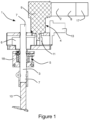
- FIG. 1 illustrates a front view of an example of an intermittent actuation device 1 for an agricultural tool 10.
- a housing 2 houses a mechanical drive chain 4 connected to a shaft 3 for actuating one or more agricultural tools 10.
- the housing 2 in addition to maintaining and protecting the elements of the mechanical drive chain, makes it possible to attach the intermittent actuation device 1 to the chassis of a vehicle or to an accessory of a vehicle by means of a fixing interface 13.
- the drive chain 4 makes it possible to produce angular movements of the shaft 3 in order to position the work tool(s) either in the working position or in the position for avoiding an obstacle, in particular a plant to be bypassed, such as for example a vine.
- the working position the tool(s) are aligned with a row of plants between which mechanical work of the earth must be carried out.
- the avoidance position the tool(s) are moved so as not to come into contact with the plants and thus avoid any damage to them.
- the mechanical drive chain 4 comprises an electric servomotor 8 provided with a control module 17.
- the servomotor 8 drives a reducer 9.
- This motor-reducer assembly makes it possible to use a motor inexpensive, using the reducer to generate sufficient torque to operate the tools being worked in the soil.
- a 600W servomotor rotating between 2500 and 6000 rpm, with a reduction of 100, allows very favorable results to be obtained with tools such as hoeing blades or weeding discs.
- the reducer 9 also serves as an angle transmission, preferably at 90°. It drives a driving pinion 11, cooperating with a driven pinion 6.
- the actuating shaft 3 passes through the driven pinion 6 at its center and remains integral with the latter, with an assembly by keying, gluing or tightening or using axial splines preventing the shaft from rotating without the driven pinion 6.
- the two ends 7 of the actuating shaft extend beyond the housing 2 and are thus accessible to provide two connection points with one or more agricultural tools 10.
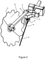
- FIG 2 illustrates an example of an agricultural tool 10 comprising two arms 16 for connection with each of the ends 7 of the drive shaft 3.
- the two attachment points of the tool at the two ends 7 of the shaft 3 ensure a high level of rigidity and an assembly resistant to the often very high forces generated when working in the ground.
- the agricultural tool 10 comprises a preferably curved disc 14, provided with peripheral teeth 15.
- the two arms 16 serve as a tool holder.
- the actuating shaft 3 makes it possible to position the tool in the working position or in the obstacle avoidance position as previously described.
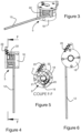
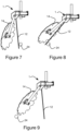
- Obstacle avoidance management is performed by means of an obstacle detector 5, connected to the control module 17 of the servomotor. Depending on the detection of obstacles, the control module actuates the servomotor in one direction to place the tool in the working position, or in the opposite direction, to place the tool in the obstacle avoidance position, as shown in the examples of Figures 7, 8 and 9 .
- detectors such as one or more cameras, one or more radars or lidars, etc.
- the control module When the probe contacts a plant and moves angularly while advancing towards the plant, the control module is designed to control a movement of the tool(s) away from the plant, in the avoidance position. Once the plant has been passed, the probe is free and a return spring 23 allows it to return to its default position. The control module is then designed to control movement of the tool(s) into the working position.
- Two arrangements can be used for the ring 18. It can be fixed relative to the actuating shaft, thus creating a differential control. It can be fixed relative to the housing, which creates an absolute control.
- FIGs 7, 8 and 9 illustrate an example of a work sequence.
- the sensor 12 comes into contact with the plant and begins to move angularly.
- the sensor is angularly offset, the movement information has been transmitted to the control module which sends an instruction to move the tool in the avoidance position to the drive mechanical chain.
- the probe is released and returns to its initial position, the movement information is transmitted to the control module which sends an instruction to move the tool to the working position to the mechanical drive chain.
- FIG 10 illustrates a variant of use of the actuating device 1 in which the tool 10 is a simple blade arranged at the lower end of the shaft 3.
- An opening tooth 25 is also fixed to the housing 2.
- the opening blade is fixed and arranged so as to be offset with respect to the alignment of plants.
Landscapes
- Life Sciences & Earth Sciences (AREA)
- Engineering & Computer Science (AREA)
- Mechanical Engineering (AREA)
- Soil Sciences (AREA)
- Environmental Sciences (AREA)
- Soil Working Implements (AREA)
- Agricultural Machines (AREA)
Claims (7)
- Intermittierende Betätigungsvorrichtung (1) für ein landwirtschaftliches Gerät (10) zum Positionieren mindestens eines landwirtschaftlichen Geräts (10) in einem Arbeitsraum, der durch voneinander beabstandete Hindernisse (24) unterbrochen ist, mit:- ein Gehäuse (2), das mit einem Fahrgestell eines landwirtschaftlichen Fahrzeugs verbunden werden kann;- eine Antriebswelle (3) für mindestens ein landwirtschaftliches Gerät;- eine Antriebskette (4) für die Antriebswelle (3), die in dem Gehäuse angeordnet ist und eine intermittierende Positionierung des mindestens einen landwirtschaftlichen Geräts (10) im Arbeitsraum ermöglicht, wobei die Antriebskette (4) ein Steuermodul (17) umfasst;- einen Detektor (5) für zu umfahrende Hindernisse, der mit dem Steuermodul (17) verbunden ist;- wobei die Antriebswelle (3) durch ein angetriebenes Ritzel (6) verläuft, das mit der Antriebskette (4) verbunden und in dem Gehäuse angeordnet ist;- wobei die Antriebswelle (3) zwei Enden (7) aufweist, wobei sich jedes der beiden Enden aus dem Gehäuse (2) heraus erstreckt, um den Anschluss von landwirtschaftlichen Geräten (10) an jedes der beiden Enden zu ermöglichen.
- Betätigungsvorrichtung nach Anspruch 1, bei der die Antriebskette (4) einen elektrischen Servomotor (8) umfasst, der ein Untersetzungsgetriebe (9) und ein Antriebsritzel (11) antreibt.
- Betätigungsvorrichtung nach Anspruch 2, wobei das Untersetzungsgetriebe (9) auch als Winkelgetriebe zur Betätigung des angetriebenen Ritzels (6) durch das treibende Ritzel (11) dient, wobei das treibende Ritzel (11) und die Antriebswelle (3) koaxial angeordnet sind.
- Betätigungsvorrichtung nach Anspruch 1, bei der der Hindernisdetektor (5) einen Taster (12) umfasst, der winkelbeweglich und mit einem Detektor (19) für die Winkelposition des Tasters verbunden ist.
- Betätigungsvorrichtung nach Anspruch 4, bei der der Positionsdetektor (19) ein Zahnrad (20) aufweist, das mit einem Zahnkranz (21) zusammenwirkt.
- Betätigungsvorrichtung nach Anspruch 4, bei der der Taster (12) eine Rückstellfeder (23) aufweist.
- Betätigungsvorrichtung nach einem der Ansprüche 1 bis 6, wobei das landwirtschaftliche Gerät (10) eine gekrümmte Scheibe (14) mit einer Vielzahl von Zähnen (15) ist, die über zwei Arme (16) mit der Antriebswelle (3) verbunden ist, wobei jeder der Arme mit einem gegenüberliegenden Ende (7) der Antriebswelle (3) verbunden ist.
Applications Claiming Priority (2)
| Application Number | Priority Date | Filing Date | Title |
|---|---|---|---|
| FR2106688A FR3124349B1 (fr) | 2021-06-23 | 2021-06-23 | Dispositif d’actionnement intermittent pour outil agricole |
| PCT/IB2022/054101 WO2022269375A1 (fr) | 2021-06-23 | 2022-05-04 | Dispositif d'actionnement intermittent pour outil agricole |
Publications (3)
| Publication Number | Publication Date |
|---|---|
| EP4329465A1 EP4329465A1 (de) | 2024-03-06 |
| EP4329465C0 EP4329465C0 (de) | 2025-01-01 |
| EP4329465B1 true EP4329465B1 (de) | 2025-01-01 |
Family
ID=76807900
Family Applications (1)
| Application Number | Title | Priority Date | Filing Date |
|---|---|---|---|
| EP22723484.6A Active EP4329465B1 (de) | 2021-06-23 | 2022-05-04 | Intermittierende betätigungsvorrichtung für landwirtschaftliches gerät |
Country Status (3)
| Country | Link |
|---|---|
| EP (1) | EP4329465B1 (de) |
| FR (1) | FR3124349B1 (de) |
| WO (1) | WO2022269375A1 (de) |
Families Citing this family (2)
| Publication number | Priority date | Publication date | Assignee | Title |
|---|---|---|---|---|
| FR3146257B1 (fr) | 2023-03-03 | 2025-03-07 | Etablissement Boisselet | Procede et dispositif pour le travail mecanique du sol entre les plants d'une meme rangee |
| WO2025190461A1 (de) * | 2024-03-14 | 2025-09-18 | Clemens Gmbh & Co. Kg | Bearbeitungsgerät und verfahren zum betreiben eines bearbeitungsgerätes |
Family Cites Families (8)
| Publication number | Priority date | Publication date | Assignee | Title |
|---|---|---|---|---|
| US3177950A (en) * | 1963-02-18 | 1965-04-13 | Laikam Plow Co Inc | Vineyard plow |
| FR1390651A (fr) * | 1964-03-31 | 1965-02-26 | Dispositif bineur-décavaillonneur | |
| DE3222503A1 (de) * | 1982-06-16 | 1983-12-22 | Erwin 6741 Billigheim-Ingenheim Fehrenbach | Stockraeumgeraet |
| SU1436899A1 (ru) * | 1985-02-11 | 1988-11-15 | Грузинский Научно-Исследовательский Институт Механизации И Электрификации Сельского Хозяйства Им.К.М.Амираджиби | Устройство дл обработки почвы в р дах растений |
| DE3916852C1 (de) | 1989-05-24 | 1990-03-15 | Clemens Und Co Kg, 5560 Wittlich, De | |
| FR2953095B1 (fr) | 2009-11-30 | 2012-02-10 | Gard Ets | Dispositif interceps multifonctions |
| ITBA20130057A1 (it) * | 2013-07-16 | 2013-10-16 | Paparella Domenico Autorimessaggi O | Meccanismo scavallatore interceppo |
| FR3093273B1 (fr) | 2019-02-28 | 2021-06-11 | Vitibot | Outils pour le travail du sol entre les ceps |
-
2021
- 2021-06-23 FR FR2106688A patent/FR3124349B1/fr active Active
-
2022
- 2022-05-04 WO PCT/IB2022/054101 patent/WO2022269375A1/fr not_active Ceased
- 2022-05-04 EP EP22723484.6A patent/EP4329465B1/de active Active
Also Published As
| Publication number | Publication date |
|---|---|
| FR3124349B1 (fr) | 2023-05-26 |
| FR3124349A1 (fr) | 2022-12-30 |
| EP4329465A1 (de) | 2024-03-06 |
| WO2022269375A1 (fr) | 2022-12-29 |
| EP4329465C0 (de) | 2025-01-01 |
Similar Documents
| Publication | Publication Date | Title |
|---|---|---|
| EP3645376B1 (de) | Karosserie eines landwirtschaftlichen fahrzeugs mit verstellbarer breite und landwirtschaftliches fahrzeug | |
| WO2022269375A1 (fr) | Dispositif d'actionnement intermittent pour outil agricole | |
| EP2852521B1 (de) | Anhänger mit einer deportierten anspannenvorrichtung | |
| EP3259970B1 (de) | Landwirtschaftliche werkzeughalterungsvorrichtung, die die einhaltung der reihen erleichtert, entsprechendes montageverfahren und entsprechendes landwirtschaftliches system | |
| FR2957220A1 (fr) | Tracteur enjambeur | |
| FR2557193A1 (fr) | Dispositif a tariere automoteur de forage du sol | |
| EP3118378B1 (de) | Motorisierte und mobile arbeitsmaschine | |
| FR3063969A1 (fr) | Tracteur multitache electrique | |
| FR2617366A1 (fr) | Herse rotative | |
| FR2687532A1 (fr) | Appareil de binage mecanique inter plants. | |
| FR3081282A1 (fr) | Dispositif de desherbage combinant deux elements de desherbage mecanique | |
| FR2953365A1 (fr) | Tracteur enjambeur | |
| FR3091462A1 (fr) | Dispositif de faucheuse-débroussailleuse et engin roulant motorisé équipé d’un tel dispositif | |
| FR2979519A1 (fr) | Procede et machine de travail du sol entre des plantations | |
| WO1997024025A1 (fr) | Dispositif d'ameublissement du sol | |
| EP0226585B1 (de) | Anbauvorrichtung | |
| EP0019505A1 (de) | Anbaugerät zum Beschneiden und Entfernen von Gestrüpp | |
| FR3002109A3 (fr) | Machine interceps pour le travail de la terre | |
| FR3155408A1 (fr) | Système d’entretien inter-plantes pour plantations en ligne | |
| FR3126844A1 (fr) | Dispositif de contrôle de l’enherbement sous un rang de plantes | |
| FR2861532A1 (fr) | Machine de travail du sol a bati ameliore | |
| FR2917266A1 (fr) | Dispositif de traitement des sols muni d'un systeme a dents a mouvement alternatif angulaire | |
| FR3055510B1 (fr) | Vehicule autoporte de coupe et de broyage de vegetaux | |
| EP1523233B1 (de) | Heumaschine | |
| EP4415509A1 (de) | Vorrichtung und verfahren zur mechanischen pflege eines rasens zur begrenzung des wachstums von unkraut |
Legal Events
| Date | Code | Title | Description |
|---|---|---|---|
| STAA | Information on the status of an ep patent application or granted ep patent |
Free format text: STATUS: UNKNOWN |
|
| STAA | Information on the status of an ep patent application or granted ep patent |
Free format text: STATUS: THE INTERNATIONAL PUBLICATION HAS BEEN MADE |
|
| PUAI | Public reference made under article 153(3) epc to a published international application that has entered the european phase |
Free format text: ORIGINAL CODE: 0009012 |
|
| STAA | Information on the status of an ep patent application or granted ep patent |
Free format text: STATUS: REQUEST FOR EXAMINATION WAS MADE |
|
| 17P | Request for examination filed |
Effective date: 20231201 |
|
| AK | Designated contracting states |
Kind code of ref document: A1 Designated state(s): AL AT BE BG CH CY CZ DE DK EE ES FI FR GB GR HR HU IE IS IT LI LT LU LV MC MK MT NL NO PL PT RO RS SE SI SK SM TR |
|
| GRAP | Despatch of communication of intention to grant a patent |
Free format text: ORIGINAL CODE: EPIDOSNIGR1 |
|
| STAA | Information on the status of an ep patent application or granted ep patent |
Free format text: STATUS: GRANT OF PATENT IS INTENDED |
|
| INTG | Intention to grant announced |
Effective date: 20240925 |
|
| GRAS | Grant fee paid |
Free format text: ORIGINAL CODE: EPIDOSNIGR3 |
|
| GRAA | (expected) grant |
Free format text: ORIGINAL CODE: 0009210 |
|
| STAA | Information on the status of an ep patent application or granted ep patent |
Free format text: STATUS: THE PATENT HAS BEEN GRANTED |
|
| AK | Designated contracting states |
Kind code of ref document: B1 Designated state(s): AL AT BE BG CH CY CZ DE DK EE ES FI FR GB GR HR HU IE IS IT LI LT LU LV MC MK MT NL NO PL PT RO RS SE SI SK SM TR |
|
| REG | Reference to a national code |
Ref country code: GB Ref legal event code: FG4D Free format text: NOT ENGLISH |
|
| REG | Reference to a national code |
Ref country code: CH Ref legal event code: EP |
|
| REG | Reference to a national code |
Ref country code: DE Ref legal event code: R096 Ref document number: 602022009396 Country of ref document: DE |
|
| REG | Reference to a national code |
Ref country code: IE Ref legal event code: FG4D Free format text: LANGUAGE OF EP DOCUMENT: FRENCH |
|
| U01 | Request for unitary effect filed |
Effective date: 20250128 |
|
| U07 | Unitary effect registered |
Designated state(s): AT BE BG DE DK EE FI FR IT LT LU LV MT NL PT RO SE SI Effective date: 20250203 |
|
| U20 | Renewal fee for the european patent with unitary effect paid |
Year of fee payment: 4 Effective date: 20250303 |
|
| PG25 | Lapsed in a contracting state [announced via postgrant information from national office to epo] |
Ref country code: PL Free format text: LAPSE BECAUSE OF FAILURE TO SUBMIT A TRANSLATION OF THE DESCRIPTION OR TO PAY THE FEE WITHIN THE PRESCRIBED TIME-LIMIT Effective date: 20250101 |
|
| PG25 | Lapsed in a contracting state [announced via postgrant information from national office to epo] |
Ref country code: ES Free format text: LAPSE BECAUSE OF FAILURE TO SUBMIT A TRANSLATION OF THE DESCRIPTION OR TO PAY THE FEE WITHIN THE PRESCRIBED TIME-LIMIT Effective date: 20250101 |
|
| PG25 | Lapsed in a contracting state [announced via postgrant information from national office to epo] |
Ref country code: NO Free format text: LAPSE BECAUSE OF FAILURE TO SUBMIT A TRANSLATION OF THE DESCRIPTION OR TO PAY THE FEE WITHIN THE PRESCRIBED TIME-LIMIT Effective date: 20250401 Ref country code: IS Free format text: LAPSE BECAUSE OF FAILURE TO SUBMIT A TRANSLATION OF THE DESCRIPTION OR TO PAY THE FEE WITHIN THE PRESCRIBED TIME-LIMIT Effective date: 20250501 |
|
| PG25 | Lapsed in a contracting state [announced via postgrant information from national office to epo] |
Ref country code: HR Free format text: LAPSE BECAUSE OF FAILURE TO SUBMIT A TRANSLATION OF THE DESCRIPTION OR TO PAY THE FEE WITHIN THE PRESCRIBED TIME-LIMIT Effective date: 20250101 |
|
| PG25 | Lapsed in a contracting state [announced via postgrant information from national office to epo] |
Ref country code: GR Free format text: LAPSE BECAUSE OF FAILURE TO SUBMIT A TRANSLATION OF THE DESCRIPTION OR TO PAY THE FEE WITHIN THE PRESCRIBED TIME-LIMIT Effective date: 20250402 |
|
| PG25 | Lapsed in a contracting state [announced via postgrant information from national office to epo] |
Ref country code: CZ Free format text: LAPSE BECAUSE OF FAILURE TO SUBMIT A TRANSLATION OF THE DESCRIPTION OR TO PAY THE FEE WITHIN THE PRESCRIBED TIME-LIMIT Effective date: 20250101 |
|
| PG25 | Lapsed in a contracting state [announced via postgrant information from national office to epo] |
Ref country code: SM Free format text: LAPSE BECAUSE OF FAILURE TO SUBMIT A TRANSLATION OF THE DESCRIPTION OR TO PAY THE FEE WITHIN THE PRESCRIBED TIME-LIMIT Effective date: 20250101 |
|
| PG25 | Lapsed in a contracting state [announced via postgrant information from national office to epo] |
Ref country code: SK Free format text: LAPSE BECAUSE OF FAILURE TO SUBMIT A TRANSLATION OF THE DESCRIPTION OR TO PAY THE FEE WITHIN THE PRESCRIBED TIME-LIMIT Effective date: 20250101 |
|
| PLBE | No opposition filed within time limit |
Free format text: ORIGINAL CODE: 0009261 |
|
| STAA | Information on the status of an ep patent application or granted ep patent |
Free format text: STATUS: NO OPPOSITION FILED WITHIN TIME LIMIT |
|
| REG | Reference to a national code |
Ref country code: CH Ref legal event code: L10 Free format text: ST27 STATUS EVENT CODE: U-0-0-L10-L00 (AS PROVIDED BY THE NATIONAL OFFICE) Effective date: 20251112 |
|
| 26N | No opposition filed |
Effective date: 20251002 |
|
| REG | Reference to a national code |
Ref country code: CH Ref legal event code: H13 Free format text: ST27 STATUS EVENT CODE: U-0-0-H10-H13 (AS PROVIDED BY THE NATIONAL OFFICE) Effective date: 20251223 |
|
| PG25 | Lapsed in a contracting state [announced via postgrant information from national office to epo] |
Ref country code: CH Free format text: LAPSE BECAUSE OF NON-PAYMENT OF DUE FEES Effective date: 20250531 |
|
| PG25 | Lapsed in a contracting state [announced via postgrant information from national office to epo] |
Ref country code: MC Free format text: LAPSE BECAUSE OF FAILURE TO SUBMIT A TRANSLATION OF THE DESCRIPTION OR TO PAY THE FEE WITHIN THE PRESCRIBED TIME-LIMIT Effective date: 20250101 |
|
| PG25 | Lapsed in a contracting state [announced via postgrant information from national office to epo] |
Ref country code: IE Free format text: LAPSE BECAUSE OF NON-PAYMENT OF DUE FEES Effective date: 20250504 |
|
| U20 | Renewal fee for the european patent with unitary effect paid |
Year of fee payment: 5 Effective date: 20260407 |