EP4329677B1 - Systèmes d'implant orthopédique comprenant des caractéristiques de transfert de plan - Google Patents
Systèmes d'implant orthopédique comprenant des caractéristiques de transfert de plan Download PDFInfo
- Publication number
- EP4329677B1 EP4329677B1 EP22720870.9A EP22720870A EP4329677B1 EP 4329677 B1 EP4329677 B1 EP 4329677B1 EP 22720870 A EP22720870 A EP 22720870A EP 4329677 B1 EP4329677 B1 EP 4329677B1
- Authority
- EP
- European Patent Office
- Prior art keywords
- implant
- transfer
- guide
- bone
- transfer members
- Prior art date
- Legal status (The legal status is an assumption and is not a legal conclusion. Google has not performed a legal analysis and makes no representation as to the accuracy of the status listed.)
- Active
Links
Images













Classifications
-
- A—HUMAN NECESSITIES
- A61—MEDICAL OR VETERINARY SCIENCE; HYGIENE
- A61F—FILTERS IMPLANTABLE INTO BLOOD VESSELS; PROSTHESES; DEVICES PROVIDING PATENCY TO, OR PREVENTING COLLAPSING OF, TUBULAR STRUCTURES OF THE BODY, e.g. STENTS; ORTHOPAEDIC, NURSING OR CONTRACEPTIVE DEVICES; FOMENTATION; TREATMENT OR PROTECTION OF EYES OR EARS; BANDAGES, DRESSINGS OR ABSORBENT PADS; FIRST-AID KITS
- A61F2/00—Filters implantable into blood vessels; Prostheses, i.e. artificial substitutes or replacements for parts of the body; Appliances for connecting them with the body; Devices providing patency to, or preventing collapsing of, tubular structures of the body, e.g. stents
- A61F2/02—Prostheses implantable into the body
- A61F2/30—Joints
- A61F2/46—Special tools for implanting artificial joints
- A61F2/4603—Special tools for implanting artificial joints for insertion or extraction of endoprosthetic joints or of accessories thereof
- A61F2/4612—Special tools for implanting artificial joints for insertion or extraction of endoprosthetic joints or of accessories thereof of shoulders
-
- A—HUMAN NECESSITIES
- A61—MEDICAL OR VETERINARY SCIENCE; HYGIENE
- A61B—DIAGNOSIS; SURGERY; IDENTIFICATION
- A61B17/00—Surgical instruments, devices or methods
- A61B17/16—Instruments for performing osteoclasis; Drills or chisels for bones; Trepans
- A61B17/17—Guides or aligning means for drills, mills, pins or wires
- A61B17/1725—Guides or aligning means for drills, mills, pins or wires for applying transverse screws or pins through intramedullary nails or pins
-
- A—HUMAN NECESSITIES
- A61—MEDICAL OR VETERINARY SCIENCE; HYGIENE
- A61B—DIAGNOSIS; SURGERY; IDENTIFICATION
- A61B17/00—Surgical instruments, devices or methods
- A61B17/16—Instruments for performing osteoclasis; Drills or chisels for bones; Trepans
- A61B17/17—Guides or aligning means for drills, mills, pins or wires
- A61B17/1739—Guides or aligning means for drills, mills, pins or wires specially adapted for particular parts of the body
- A61B17/1778—Guides or aligning means for drills, mills, pins or wires specially adapted for particular parts of the body for the shoulder
-
- A—HUMAN NECESSITIES
- A61—MEDICAL OR VETERINARY SCIENCE; HYGIENE
- A61B—DIAGNOSIS; SURGERY; IDENTIFICATION
- A61B17/00—Surgical instruments, devices or methods
- A61B17/56—Surgical instruments or methods for treatment of bones or joints; Devices specially adapted therefor
-
- A—HUMAN NECESSITIES
- A61—MEDICAL OR VETERINARY SCIENCE; HYGIENE
- A61B—DIAGNOSIS; SURGERY; IDENTIFICATION
- A61B34/00—Computer-aided surgery; Manipulators or robots specially adapted for use in surgery
- A61B34/10—Computer-aided planning, simulation or modelling of surgical operations
-
- A—HUMAN NECESSITIES
- A61—MEDICAL OR VETERINARY SCIENCE; HYGIENE
- A61F—FILTERS IMPLANTABLE INTO BLOOD VESSELS; PROSTHESES; DEVICES PROVIDING PATENCY TO, OR PREVENTING COLLAPSING OF, TUBULAR STRUCTURES OF THE BODY, e.g. STENTS; ORTHOPAEDIC, NURSING OR CONTRACEPTIVE DEVICES; FOMENTATION; TREATMENT OR PROTECTION OF EYES OR EARS; BANDAGES, DRESSINGS OR ABSORBENT PADS; FIRST-AID KITS
- A61F2/00—Filters implantable into blood vessels; Prostheses, i.e. artificial substitutes or replacements for parts of the body; Appliances for connecting them with the body; Devices providing patency to, or preventing collapsing of, tubular structures of the body, e.g. stents
- A61F2/02—Prostheses implantable into the body
- A61F2/30—Joints
- A61F2/30721—Accessories
- A61F2/30734—Modular inserts, sleeves or augments, e.g. placed on proximal part of stem for fixation purposes or wedges for bridging a bone defect
-
- A—HUMAN NECESSITIES
- A61—MEDICAL OR VETERINARY SCIENCE; HYGIENE
- A61F—FILTERS IMPLANTABLE INTO BLOOD VESSELS; PROSTHESES; DEVICES PROVIDING PATENCY TO, OR PREVENTING COLLAPSING OF, TUBULAR STRUCTURES OF THE BODY, e.g. STENTS; ORTHOPAEDIC, NURSING OR CONTRACEPTIVE DEVICES; FOMENTATION; TREATMENT OR PROTECTION OF EYES OR EARS; BANDAGES, DRESSINGS OR ABSORBENT PADS; FIRST-AID KITS
- A61F2/00—Filters implantable into blood vessels; Prostheses, i.e. artificial substitutes or replacements for parts of the body; Appliances for connecting them with the body; Devices providing patency to, or preventing collapsing of, tubular structures of the body, e.g. stents
- A61F2/02—Prostheses implantable into the body
- A61F2/30—Joints
- A61F2/30721—Accessories
- A61F2/30744—End caps, e.g. for closing an endoprosthetic cavity
-
- A—HUMAN NECESSITIES
- A61—MEDICAL OR VETERINARY SCIENCE; HYGIENE
- A61F—FILTERS IMPLANTABLE INTO BLOOD VESSELS; PROSTHESES; DEVICES PROVIDING PATENCY TO, OR PREVENTING COLLAPSING OF, TUBULAR STRUCTURES OF THE BODY, e.g. STENTS; ORTHOPAEDIC, NURSING OR CONTRACEPTIVE DEVICES; FOMENTATION; TREATMENT OR PROTECTION OF EYES OR EARS; BANDAGES, DRESSINGS OR ABSORBENT PADS; FIRST-AID KITS
- A61F2/00—Filters implantable into blood vessels; Prostheses, i.e. artificial substitutes or replacements for parts of the body; Appliances for connecting them with the body; Devices providing patency to, or preventing collapsing of, tubular structures of the body, e.g. stents
- A61F2/02—Prostheses implantable into the body
- A61F2/30—Joints
- A61F2/3094—Designing or manufacturing processes
- A61F2/30942—Designing or manufacturing processes for designing or making customized prostheses, e.g. using templates, CT or NMR scans, finite-element analysis or CAD-CAM techniques
-
- A—HUMAN NECESSITIES
- A61—MEDICAL OR VETERINARY SCIENCE; HYGIENE
- A61F—FILTERS IMPLANTABLE INTO BLOOD VESSELS; PROSTHESES; DEVICES PROVIDING PATENCY TO, OR PREVENTING COLLAPSING OF, TUBULAR STRUCTURES OF THE BODY, e.g. STENTS; ORTHOPAEDIC, NURSING OR CONTRACEPTIVE DEVICES; FOMENTATION; TREATMENT OR PROTECTION OF EYES OR EARS; BANDAGES, DRESSINGS OR ABSORBENT PADS; FIRST-AID KITS
- A61F2/00—Filters implantable into blood vessels; Prostheses, i.e. artificial substitutes or replacements for parts of the body; Appliances for connecting them with the body; Devices providing patency to, or preventing collapsing of, tubular structures of the body, e.g. stents
- A61F2/02—Prostheses implantable into the body
- A61F2/30—Joints
- A61F2/40—Joints for shoulders
- A61F2/4081—Glenoid components, e.g. cups
-
- A—HUMAN NECESSITIES
- A61—MEDICAL OR VETERINARY SCIENCE; HYGIENE
- A61B—DIAGNOSIS; SURGERY; IDENTIFICATION
- A61B17/00—Surgical instruments, devices or methods
- A61B17/56—Surgical instruments or methods for treatment of bones or joints; Devices specially adapted therefor
- A61B2017/568—Surgical instruments or methods for treatment of bones or joints; Devices specially adapted therefor produced with shape and dimensions specific for an individual patient
-
- A—HUMAN NECESSITIES
- A61—MEDICAL OR VETERINARY SCIENCE; HYGIENE
- A61B—DIAGNOSIS; SURGERY; IDENTIFICATION
- A61B34/00—Computer-aided surgery; Manipulators or robots specially adapted for use in surgery
- A61B34/10—Computer-aided planning, simulation or modelling of surgical operations
- A61B2034/101—Computer-aided simulation of surgical operations
- A61B2034/102—Modelling of surgical devices, implants or prosthesis
-
- A—HUMAN NECESSITIES
- A61—MEDICAL OR VETERINARY SCIENCE; HYGIENE
- A61B—DIAGNOSIS; SURGERY; IDENTIFICATION
- A61B34/00—Computer-aided surgery; Manipulators or robots specially adapted for use in surgery
- A61B34/10—Computer-aided planning, simulation or modelling of surgical operations
- A61B2034/101—Computer-aided simulation of surgical operations
- A61B2034/105—Modelling of the patient, e.g. for ligaments or bones
-
- A—HUMAN NECESSITIES
- A61—MEDICAL OR VETERINARY SCIENCE; HYGIENE
- A61B—DIAGNOSIS; SURGERY; IDENTIFICATION
- A61B34/00—Computer-aided surgery; Manipulators or robots specially adapted for use in surgery
- A61B34/10—Computer-aided planning, simulation or modelling of surgical operations
- A61B2034/107—Visualisation of planned trajectories or target regions
-
- A—HUMAN NECESSITIES
- A61—MEDICAL OR VETERINARY SCIENCE; HYGIENE
- A61B—DIAGNOSIS; SURGERY; IDENTIFICATION
- A61B34/00—Computer-aided surgery; Manipulators or robots specially adapted for use in surgery
- A61B34/10—Computer-aided planning, simulation or modelling of surgical operations
- A61B2034/108—Computer aided selection or customisation of medical implants or cutting guides
-
- A—HUMAN NECESSITIES
- A61—MEDICAL OR VETERINARY SCIENCE; HYGIENE
- A61B—DIAGNOSIS; SURGERY; IDENTIFICATION
- A61B34/00—Computer-aided surgery; Manipulators or robots specially adapted for use in surgery
- A61B34/25—User interfaces for surgical systems
-
- A—HUMAN NECESSITIES
- A61—MEDICAL OR VETERINARY SCIENCE; HYGIENE
- A61F—FILTERS IMPLANTABLE INTO BLOOD VESSELS; PROSTHESES; DEVICES PROVIDING PATENCY TO, OR PREVENTING COLLAPSING OF, TUBULAR STRUCTURES OF THE BODY, e.g. STENTS; ORTHOPAEDIC, NURSING OR CONTRACEPTIVE DEVICES; FOMENTATION; TREATMENT OR PROTECTION OF EYES OR EARS; BANDAGES, DRESSINGS OR ABSORBENT PADS; FIRST-AID KITS
- A61F2/00—Filters implantable into blood vessels; Prostheses, i.e. artificial substitutes or replacements for parts of the body; Appliances for connecting them with the body; Devices providing patency to, or preventing collapsing of, tubular structures of the body, e.g. stents
- A61F2/02—Prostheses implantable into the body
- A61F2/30—Joints
- A61F2002/30001—Additional features of subject-matter classified in A61F2/28, A61F2/30 and subgroups thereof
- A61F2002/30316—The prosthesis having different structural features at different locations within the same prosthesis; Connections between prosthetic parts; Special structural features of bone or joint prostheses not otherwise provided for
- A61F2002/30329—Connections or couplings between prosthetic parts, e.g. between modular parts; Connecting elements
- A61F2002/30331—Connections or couplings between prosthetic parts, e.g. between modular parts; Connecting elements made by longitudinally pushing a protrusion into a complementarily-shaped recess, e.g. held by friction fit
- A61F2002/30354—Cylindrically-shaped protrusion and recess, e.g. cylinder of circular basis
-
- A—HUMAN NECESSITIES
- A61—MEDICAL OR VETERINARY SCIENCE; HYGIENE
- A61F—FILTERS IMPLANTABLE INTO BLOOD VESSELS; PROSTHESES; DEVICES PROVIDING PATENCY TO, OR PREVENTING COLLAPSING OF, TUBULAR STRUCTURES OF THE BODY, e.g. STENTS; ORTHOPAEDIC, NURSING OR CONTRACEPTIVE DEVICES; FOMENTATION; TREATMENT OR PROTECTION OF EYES OR EARS; BANDAGES, DRESSINGS OR ABSORBENT PADS; FIRST-AID KITS
- A61F2/00—Filters implantable into blood vessels; Prostheses, i.e. artificial substitutes or replacements for parts of the body; Appliances for connecting them with the body; Devices providing patency to, or preventing collapsing of, tubular structures of the body, e.g. stents
- A61F2/02—Prostheses implantable into the body
- A61F2/30—Joints
- A61F2002/30001—Additional features of subject-matter classified in A61F2/28, A61F2/30 and subgroups thereof
- A61F2002/30316—The prosthesis having different structural features at different locations within the same prosthesis; Connections between prosthetic parts; Special structural features of bone or joint prostheses not otherwise provided for
- A61F2002/30329—Connections or couplings between prosthetic parts, e.g. between modular parts; Connecting elements
- A61F2002/30383—Connections or couplings between prosthetic parts, e.g. between modular parts; Connecting elements made by laterally inserting a protrusion, e.g. a rib into a complementarily-shaped groove
- A61F2002/3039—Connections or couplings between prosthetic parts, e.g. between modular parts; Connecting elements made by laterally inserting a protrusion, e.g. a rib into a complementarily-shaped groove with possibility of relative movement of the rib within the groove
- A61F2002/30398—Sliding
-
- A—HUMAN NECESSITIES
- A61—MEDICAL OR VETERINARY SCIENCE; HYGIENE
- A61F—FILTERS IMPLANTABLE INTO BLOOD VESSELS; PROSTHESES; DEVICES PROVIDING PATENCY TO, OR PREVENTING COLLAPSING OF, TUBULAR STRUCTURES OF THE BODY, e.g. STENTS; ORTHOPAEDIC, NURSING OR CONTRACEPTIVE DEVICES; FOMENTATION; TREATMENT OR PROTECTION OF EYES OR EARS; BANDAGES, DRESSINGS OR ABSORBENT PADS; FIRST-AID KITS
- A61F2/00—Filters implantable into blood vessels; Prostheses, i.e. artificial substitutes or replacements for parts of the body; Appliances for connecting them with the body; Devices providing patency to, or preventing collapsing of, tubular structures of the body, e.g. stents
- A61F2/02—Prostheses implantable into the body
- A61F2/30—Joints
- A61F2002/30001—Additional features of subject-matter classified in A61F2/28, A61F2/30 and subgroups thereof
- A61F2002/30316—The prosthesis having different structural features at different locations within the same prosthesis; Connections between prosthetic parts; Special structural features of bone or joint prostheses not otherwise provided for
- A61F2002/30535—Special structural features of bone or joint prostheses not otherwise provided for
- A61F2002/30561—Special structural features of bone or joint prostheses not otherwise provided for breakable or frangible
-
- A—HUMAN NECESSITIES
- A61—MEDICAL OR VETERINARY SCIENCE; HYGIENE
- A61F—FILTERS IMPLANTABLE INTO BLOOD VESSELS; PROSTHESES; DEVICES PROVIDING PATENCY TO, OR PREVENTING COLLAPSING OF, TUBULAR STRUCTURES OF THE BODY, e.g. STENTS; ORTHOPAEDIC, NURSING OR CONTRACEPTIVE DEVICES; FOMENTATION; TREATMENT OR PROTECTION OF EYES OR EARS; BANDAGES, DRESSINGS OR ABSORBENT PADS; FIRST-AID KITS
- A61F2/00—Filters implantable into blood vessels; Prostheses, i.e. artificial substitutes or replacements for parts of the body; Appliances for connecting them with the body; Devices providing patency to, or preventing collapsing of, tubular structures of the body, e.g. stents
- A61F2/02—Prostheses implantable into the body
- A61F2/30—Joints
- A61F2002/30001—Additional features of subject-matter classified in A61F2/28, A61F2/30 and subgroups thereof
- A61F2002/30316—The prosthesis having different structural features at different locations within the same prosthesis; Connections between prosthetic parts; Special structural features of bone or joint prostheses not otherwise provided for
- A61F2002/30535—Special structural features of bone or joint prostheses not otherwise provided for
- A61F2002/30617—Visible markings for adjusting, locating or measuring
-
- A—HUMAN NECESSITIES
- A61—MEDICAL OR VETERINARY SCIENCE; HYGIENE
- A61F—FILTERS IMPLANTABLE INTO BLOOD VESSELS; PROSTHESES; DEVICES PROVIDING PATENCY TO, OR PREVENTING COLLAPSING OF, TUBULAR STRUCTURES OF THE BODY, e.g. STENTS; ORTHOPAEDIC, NURSING OR CONTRACEPTIVE DEVICES; FOMENTATION; TREATMENT OR PROTECTION OF EYES OR EARS; BANDAGES, DRESSINGS OR ABSORBENT PADS; FIRST-AID KITS
- A61F2/00—Filters implantable into blood vessels; Prostheses, i.e. artificial substitutes or replacements for parts of the body; Appliances for connecting them with the body; Devices providing patency to, or preventing collapsing of, tubular structures of the body, e.g. stents
- A61F2/02—Prostheses implantable into the body
- A61F2/30—Joints
- A61F2/30721—Accessories
- A61F2/30734—Modular inserts, sleeves or augments, e.g. placed on proximal part of stem for fixation purposes or wedges for bridging a bone defect
- A61F2002/30736—Augments or augmentation pieces, e.g. wedges or blocks for bridging a bone defect
-
- A—HUMAN NECESSITIES
- A61—MEDICAL OR VETERINARY SCIENCE; HYGIENE
- A61F—FILTERS IMPLANTABLE INTO BLOOD VESSELS; PROSTHESES; DEVICES PROVIDING PATENCY TO, OR PREVENTING COLLAPSING OF, TUBULAR STRUCTURES OF THE BODY, e.g. STENTS; ORTHOPAEDIC, NURSING OR CONTRACEPTIVE DEVICES; FOMENTATION; TREATMENT OR PROTECTION OF EYES OR EARS; BANDAGES, DRESSINGS OR ABSORBENT PADS; FIRST-AID KITS
- A61F2/00—Filters implantable into blood vessels; Prostheses, i.e. artificial substitutes or replacements for parts of the body; Appliances for connecting them with the body; Devices providing patency to, or preventing collapsing of, tubular structures of the body, e.g. stents
- A61F2/02—Prostheses implantable into the body
- A61F2/30—Joints
- A61F2/3094—Designing or manufacturing processes
- A61F2002/30985—Designing or manufacturing processes using three dimensional printing [3DP]
-
- A—HUMAN NECESSITIES
- A61—MEDICAL OR VETERINARY SCIENCE; HYGIENE
- A61F—FILTERS IMPLANTABLE INTO BLOOD VESSELS; PROSTHESES; DEVICES PROVIDING PATENCY TO, OR PREVENTING COLLAPSING OF, TUBULAR STRUCTURES OF THE BODY, e.g. STENTS; ORTHOPAEDIC, NURSING OR CONTRACEPTIVE DEVICES; FOMENTATION; TREATMENT OR PROTECTION OF EYES OR EARS; BANDAGES, DRESSINGS OR ABSORBENT PADS; FIRST-AID KITS
- A61F2/00—Filters implantable into blood vessels; Prostheses, i.e. artificial substitutes or replacements for parts of the body; Appliances for connecting them with the body; Devices providing patency to, or preventing collapsing of, tubular structures of the body, e.g. stents
- A61F2/02—Prostheses implantable into the body
- A61F2/30—Joints
- A61F2/40—Joints for shoulders
- A61F2/4081—Glenoid components, e.g. cups
- A61F2002/4085—Glenoid components, e.g. cups having a convex shape, e.g. hemispherical heads
-
- A—HUMAN NECESSITIES
- A61—MEDICAL OR VETERINARY SCIENCE; HYGIENE
- A61F—FILTERS IMPLANTABLE INTO BLOOD VESSELS; PROSTHESES; DEVICES PROVIDING PATENCY TO, OR PREVENTING COLLAPSING OF, TUBULAR STRUCTURES OF THE BODY, e.g. STENTS; ORTHOPAEDIC, NURSING OR CONTRACEPTIVE DEVICES; FOMENTATION; TREATMENT OR PROTECTION OF EYES OR EARS; BANDAGES, DRESSINGS OR ABSORBENT PADS; FIRST-AID KITS
- A61F2/00—Filters implantable into blood vessels; Prostheses, i.e. artificial substitutes or replacements for parts of the body; Appliances for connecting them with the body; Devices providing patency to, or preventing collapsing of, tubular structures of the body, e.g. stents
- A61F2/02—Prostheses implantable into the body
- A61F2/30—Joints
- A61F2/46—Special tools for implanting artificial joints
- A61F2/4603—Special tools for implanting artificial joints for insertion or extraction of endoprosthetic joints or of accessories thereof
- A61F2002/4629—Special tools for implanting artificial joints for insertion or extraction of endoprosthetic joints or of accessories thereof connected to the endoprosthesis or implant via a threaded connection
-
- A—HUMAN NECESSITIES
- A61—MEDICAL OR VETERINARY SCIENCE; HYGIENE
- A61F—FILTERS IMPLANTABLE INTO BLOOD VESSELS; PROSTHESES; DEVICES PROVIDING PATENCY TO, OR PREVENTING COLLAPSING OF, TUBULAR STRUCTURES OF THE BODY, e.g. STENTS; ORTHOPAEDIC, NURSING OR CONTRACEPTIVE DEVICES; FOMENTATION; TREATMENT OR PROTECTION OF EYES OR EARS; BANDAGES, DRESSINGS OR ABSORBENT PADS; FIRST-AID KITS
- A61F2/00—Filters implantable into blood vessels; Prostheses, i.e. artificial substitutes or replacements for parts of the body; Appliances for connecting them with the body; Devices providing patency to, or preventing collapsing of, tubular structures of the body, e.g. stents
- A61F2/02—Prostheses implantable into the body
- A61F2/30—Joints
- A61F2/46—Special tools for implanting artificial joints
- A61F2002/4687—Mechanical guides for implantation instruments
Definitions
- This disclosure relates to orthopaedic procedures and, more particularly, to systems for planning and implementing the repair of bone defects and restoration of functionality to a joint, including positioning implants at a surgical site based on a surgical plan.
- articular surfaces articulate relative to other bones to facilitate different types and degrees of joint movement.
- the articular surfaces can erode or experience bone loss over time due to repeated use or wear or can fracture as a result of a traumatic impact. These types of bone defects can cause joint instability and pain.
- Bone deficiencies may occur along the articular surfaces.
- Some techniques utilize a bone graft and/or implant to repair a defect adjacent the articular surfaces.
- the surgeon may utilize a guide pin to position the implant.
- WO 2014/089291 A1 discloses orthopedic guide systems and methods.
- US 2019/0015116 A1 discloses guides and instruments for improving accuracy of glenoid implant placement.
- US 2018/0125509 A1 discloses a system and method for assisting with attachment of a stock implant to a patient tissue.
- US 2018/0333263 A1 discloses implant assembly tools and methods.
- US 10,433,983 B1 discloses an adjustable pin setting targeter device.
- WO 2012/024288 A2 discloses a patient-matched acetabular alignment tool and defines the preamble of claim 1.
- This disclosure relates to planning systems, assemblies and methods.
- Implants may be positioned utilizing one or more transfer members associated with a surgical plan.
- a transfer guide for an orthopaedic procedure according to the invention is defined in claim 1.
- An orthopaedic implant may include, inter alia, a baseplate and an augment that may extend outwardly from the baseplate.
- the augment may be dimensioned to contact bone.
- the implant may include one or more transfer members that may extend from the augment.
- the one or more transfer members may be configured to contact bone.
- Each of the one or more transfer members may be coupled to the augment at a respective breakable connection.
- Transfer members may be associated with a predetermined surgical plan.
- One or more parameters of the surgical plan may be transferred to or by the transfer members for implementing a predetermined position of the respective implant.
- the surgical plan may be tailored to the individual patient, which may improve healing.
- the transfer members may be coupled directly to the implant or may be incorporated into a transfer guide or device, which may improve accuracy in positioning implants according to surgical plans.
- the disclosed techniques may reduce complexity in implementing the surgical plans, including reduced packaging and instrumentation.
- the transfer members may be single use and/or reusable, which may provide the surgeon flexibility in implementing the surgical plans.
- the one or more transfer members may be dimensioned to be at least partially axially aligned with the augment relative to the axis.
- the baseplate may include a central aperture and a plurality of peripheral apertures circumferentially distributed about the central aperture. Each of the peripheral apertures may be dimensioned to receive a respective fastener to secure the implant to bone.
- the transfer guide may include an alignment member. The alignment member may be dimensioned to be insertable into an aperture along the baseplate to limit relative rotation between the transfer guide and the implant.
- the guide body may include a passage configured to be aligned with the central aperture in an installed position.
- the passage may be dimensioned to at least partially receive a guide pin insertable through the central aperture and into bone to set a position of the implant.
- each of the transfer members is moveable axially between a first position and a second position.
- each of the transfer members includes a first portion extending radially outward from the guide body and a second portion extending axially from the first portion.
- the second portion is configured to abut tissue adjacent the implant.
- the implant may include a baseplate and an augment that may extend from the baseplate relative to an axis.
- the augment may be dimensioned to contact bone.
- the baseplate may include a central aperture and a plurality of peripheral apertures circumferentially distributed about the central aperture. Each of the peripheral apertures may be dimensioned to receive a respective fastener to secure the implant to bone.
- the guide body may include a coupling feature at least partially receivable in the central aperture to secure the transfer guide to the implant.
- the transfer guide may include an alignment member that may be dimensioned to be insertable into an aperture in the baseplate to limit relative rotation between the transfer guide and the implant.
- the coupling feature may include first threads that may mate with second threads along the central aperture to mechanically attach the transfer guide to the implant.
- the one or more transfer members may be integrally formed with the guide body.
- the coupling member may include a passage.
- the passage may be dimensioned to receive a guide pin insertable through the central aperture and into bone to set a position of the implant.
- the implant may include a baseplate and an augment that may extend outwardly from the baseplate.
- the augment may be dimensioned to contact bone.
- the transfer guide may include an abutment member that may extend outwardly from the guide body. The abutment member may be dimensioned to at least partially follow a periphery of the baseplate.
- each of the one or more transfer members may extend from the guide body to a terminal end portion.
- the one or more transfer members may include a first transfer member and a second transfer member.
- the terminal end portion of the first transfer member may have has a geometry that may differ from a geometry of the terminal end portion of the second transfer member.
- each terminal end portion may be dimensioned with respect to a predetermined surface contour of the bone.
- the one or more transfer members may include a transfer body and a transfer arm that may interconnect the guide body and the transfer body.
- the transfer body may include a contact surface that may be dimensioned with respect to a predetermined surface contour of the bone.
- the implant may include a baseplate and an augment that may extend outwardly from the baseplate.
- the augment may be dimensioned to contact bone.
- the guide body may be dimensioned to follow a periphery of the baseplate.
- the one or more transfer members may be integrally formed with the guide body.
- the transfer guide may include a plurality of fixation members that may be dimensioned to interface with a circumferential rim of the baseplate to establish a snap-fit connection.
- the baseplate may include a central aperture and a plurality of peripheral apertures circumferentially distributed about the central aperture.
- Each of the peripheral apertures may be dimensioned to receive a respective fastener to secure the implant to bone.
- the transfer guide may include one or more alignment members that may extend inwardly from the guide body. Each of the one or more alignment members may be dimensioned to be insertable into a respective one of the peripheral apertures to limit relative rotation between the transfer guide and the implant.
- the central aperture may be dimensioned to receive a coupling member.
- the coupling member may include a passage.
- the passage may be dimensioned to receive a guide pin insertable through the central aperture and into bone to set a position of the implant.
- the coupling member may be spaced apart from the transfer members in an installed position.
- the guide body may be dimensioned to encircle and at least partially receive the periphery of the baseplate.
- the implant may include a baseplate and an augment that may extend outwardly from the baseplate. The step of positioning the implant may occurs such that a surface of the augment may contact the bone.
- the method may include integrally forming the one or more transfer members with the guide body based on the at least one dimension subsequent to the step of establishing the surgical plan.
- a surgeon or user may position and orient the implant 152 based on a position of the transfer members 154 and/or transfer guide 156 relative to tissue such as bone B (see, e.g., Figures 10-12 ).
- the bone B may be a portion of a glenoid or another bone associated with a joint of a patient.
- implementing the surgical plan may include installing one or more orthopaedic implants such as the implant 152.
- the implant 152 may be installed along bone B or other tissue at a surgical site S.
- the bone B may be associated with a respective bone model 31 ( Figure 2 ).
- the implant 152 may be associated with a respective implant model 32 specified in the surgical plan 33 ( Figure 2 ).
- Step 198O may include positioning the transfer members 154 to contact tissue such as bone B at step 198Q.
- Step 198Q may occur during and/or subsequent to coupling the transfer members 154 and associated transfer guide 156 to the implant 152 at step 198P.
- Step 198O may include positioning the implant 152 together with the transfer members 154 and associated transfer guide 156 as a unit relative to the bone B or other tissue subsequent to coupling the transfer members 154 to the implant 152 at step 198P.
- Positioning the transfer member(s) 154 to contact the bone B or other tissue may occur at respective predetermined contact point(s) CP (see also Figures 10-12 and 13C ).
- the contact points CP may be defined according to the surgical plan 33 and may be distributed along a surface contour of the bone B, including along an articular surface or non-articular surface of a joint.
- the contact points CP may correspond to one or more landmarks defined by the patient anatomy, such as the glenoid rim.
- Each of the transfer members 154 may include a respective contact surface 154CS.
- the contact surface 154CS may be dimensioned with respect to one or more parameters of the surgical plan 33 determined at step 198G according to the respective contact points CP.
- One or more of the transfer members 154 may extend outwardly from the guide body 162 such that the contact surface 154CS contacts a surface contour of the bone B at the respective contact points CP.
- Each contact point CP may be a single point or a localized region along the tissue.
- the transfer members 154 may be dimensioned or configured according to the parameters or settings from the surgical plan 33 such that each of the contact surfaces 154CS of the transfer members 154 substantially mates with the bone B at only one predetermined position along the bone B to situate the implant 152 at the predetermined position and/or orientation specified in the surgical plan 33.
- Various indicia 165 may be utilized to establish the position of the transfer members 154.
- positioning the transfer members 154 at step 198Q may include aligning the marker 165M associated with the transfer member 154 and the adjacent ruler 165M to select a value along the ruler 165M (see Figure 5A ).
- the value may correspond to one or more settings determined in step 198G and/or otherwise included in the surgical plan established at step 198J.
- Step 198O may include moving the transfer members 154 in a direction DA between a first position and a second position relative to the guide body 162 and/or implant 152 based on the dimensions(s), setting(s) and/or other parameters determined at step 198G such that the transfer members 154 contact bone B at the respective contact points CP.
- Direction DA may be substantially parallel to the axis A of the transfer guide 156.
- One or more of the transfer members 154 may contact the bone B at the terminal end portion 154T, as illustrated by transfer member 154-1, and/or may contact the bone B along the periphery of the second portion 154B of the transfer member 154, as illustrated by transfer member 154-2 (see also Figures 10-12 ).
- the transfer member 154-2 may be dimensioned such that the terminal end portion 154T overhangs the bone B outwardly of the respective contact point CP (see, e.g., Figure 11 ).
- the terminal end portion 154T may overhang the bone B such that the contact point CP is established outwardly of, and is spaced apart from, an articular surface of the bone B or joint.
- the rear face 161B may be have a patient-specific geometry dimensioned to substantially follow a surface contour of a bone B associated with the articular surface of the bone B or joint (see, e.g., Figure 12 ).
- the transfer members may be established at fixed positions relative to the guide body and/or implant (see, e.g., assemblies 250, 350, 450, 55, 650, 750 and 950).
- Step 198V may include coupling an articulation member 167 to the baseplate 158, as illustrated in Figure 8 (shown in dashed lines for illustrative purposes).
- the articulation member 167 may include an articulation surface dimensioned to cooperate with an adjacent bone or implant.
- the articulation surface may have various geometries including a generally concave or convex geometry.
- Step 198V may include closing an incision made in the patient to situate the implant 152.
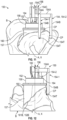
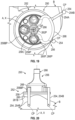
- each of the transfer members 254 may be integrally formed with the guide body 262 such that a position of each of the transfer members 254 is fixed relative to the guide body 262.
- Each of the transfer members 254 may include a first portion 254A extending radially outward from the guide body 262 and a second portion 254B extending axially between the first portion 254A and a terminal end portion 254T.
- the terminal end portion 254T and/or another surface of the second portion 254B may be configured to abut bone B or other tissue adjacent the implant 252, as illustrated in Figures 19-20 .
- a surgeon or user may position the implant 252 based on a position of the transfer members 254 and/or transfer guide 256 relative to the bone B.
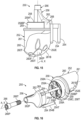
- the coupling member 266 may include threads 266T that are dimensioned to mate with threads 258T along the central aperture 258C ( Figure 16 ) to mechanically attach the transfer guide 256 to the implant 252.
- One or more of the transfer members 254 may be dimensioned to be at least partially axially aligned with the augment 260 relative to the axis X of the implant 152 and/or axis A of the transfer guide 256 in the installed position, as illustrated in Figures 15 and 20 .
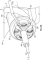
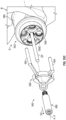
- FIGS 21A-21F illustrate various states of installing the implant 252 to bone B at a surgical site S utilizing the transfer members 254 and associated transfer guide 256. Any of the steps of the method 198 may be utilized to install the implant 252. Reference is made to the method 198 of Figure 14 for illustrative purposes.
- the method 198 may include integrally forming the transfer members 254 with the guide body 262 at step 198L based on one or more dimensions established at step 198G. Integrally forming the transfer members 254 with the guide body 262 may occur subsequent to the establishing a predetermined surgical plan at step 198J.
- the implant 252 may be positioned at the surgical site S according to positioning the transfer members 254 at step 198O.
- Step 198O may include positioning the transfer guide 256 relative to the implant 252.
- the coupling member 266 may be moved in a direction D1 to mechanically attach or otherwise secure the transfer guide 256 to the implant 252 at step 198P.
- Step 198R may include positioning the guide pin GP by moving the guide pin GP in the direction D1 and inserting the guide pin GP into the passage 266P of the coupling member 266, then through the central aperture 258P ( Figure 21C ) of the baseplate 258, and then into the bone B to set a position and orientation of the implant 252.
- the guide pin GP may enter the bone B at a position and/or orientation substantially equal to the predetermined virtual position VP and/or virtual axis VA associated with the surgical plan established at step 198J.
- the implant 252 may be secured to the surgical site S at step 198T.
- One or more fasteners F may be positioned in the peripheral apertures 258P to secure the implant 252 at step 198U.
- the guide pin GP may be removed from the implant 252 and moved in the direction D2 away from the surgical site S, as illustrated in Figures 21E-21F .
- the implant 352 may include a baseplate 358 and augment 360 extending outwardly from the baseplate 358.
- a rear face 361B of the augment 360 may establish an external surface 352E of the implant 352.
- the rear face 361B may have a patient-specific geometry dimensioned to substantially follow a surface contour of a bone B of a patient (bone B shown in dashed lines in Figure 22 for illustrative purposes).
- the transfer members 354 may be coupled to the implant 352.
- the implant 352 and each transfer member 354 may be configured to abut or contact bone B or other tissue (see, e.g., Figures 26 , 27A and 27C ).
- the implant 352 and transfer members 354 may be dimensioned utilizing any of the techniques disclosed herein, including dimensions based on a predetermined surgical plan.
- the predetermined surgical plan may be established by the planning system 20 and/or method 198.
- the assembly 350 may include a transfer guide 356 configured to interface with the implant 352.
- the transfer guide 356 may incorporate one or more of the transfer members 354.
- the terminal end portion 354T and/or another surface of the second portion 354B may be configured to abut bone B or other tissue adjacent the implant 352, as illustrated in Figure 26 .
- a surgeon or user may position the implant 352 based on a position of the transfer members 354 and/or transfer guide 356 relative to the bone B.
- Each of the transfer members 354 may be positioned relative to the guide body 362 based on a predetermined surgical plan, such as the surgical plan 33 ( Figure 2 ). In implementations, one or more surfaces of the transfer members 354 may be dimensioned based on the predetermined surgical plan.
- Each of the transfer members 354 may include a respective contact surface 354CS.
- the contact surface 354CS may extend along the terminal end portion 354T and may be dimensioned with respect to a predetermined surface contour of the bone B, as illustrated in Figure 26 .
- the predetermined surface contour may be associated with an articular surface of the bone B, a perimeter of the articular surface such as the glenoid rim of a patient, or another surface of the bone B.
- the contact surface 354CS may be dimensioned with respect to any of the techniques disclosed herein, including one or more parameters of the surgical plan 33, which may be determined at step 198G of method 198 according to respective contact points CP along the patient anatomy.
- the transfer members 354 may include a first transfer member 354-1 and a second transfer member 354-2.
- the terminal end portion 354T of the first transfer member 354-1 may have a geometry that differs from a geometry of the terminal end portion 354T of the second transfer member 354-2, including the respective the contact surfaces 354CS.
- the transfer members 354 may extend outwardly from the guide body 362 such that the contact surface 354CS contacts a surface contour of the bone B at the respective contact points CP.
- the implant 352 may be spaced apart from each of the contact points CP in response to positioning the guide pin GP in the bone B, as illustrated by Figures 27B-27C (guide pin GP shown in dashed lines in Figure 27B for illustrative purposes).
- Figures 27A-27G illustrate various states of installing the implant 352 to bone B at a surgical site S utilizing the transfer members 354 and associated transfer guide 356.
- the planning system 20 may be utilized to establish a surgical plan for installing the implant 352.
- the implant 352 may be installed utilizing any of the steps of the method 198 and/or in the same manner as the implant 252 and respective assembly 250 of Figures 21A-21F .
- the method 198 may include forming each of the contact surfaces 354CS to substantially follow the surface profile of the bone B at step 198L, which may be based on the surgical plan established at step 198J.
- the transfer members may have other geometries, as illustrated by the assembly 450 of Figures 28-30 .
- the assembly 450 may include an implant 452 and a transfer guide 456.
- At least one transfer member 454 may extend outwardly from a guide body 462 of the transfer guide 456.
- the transfer member 454 may be integrally formed with the guide body 462.
- the transfer member 454 may include a first portion (e.g., transfer arm) 454A and a second portion (e.g., transfer body) 454B extending from the first portion 454A.
- the first portion 454A may interconnect the guide body 462 and second portion 454B.
- the second portion 454B may be cantilevered from the first portion 454A such that the second portion 454B is spaced apart radially from the implant 352 relative to axes A, X.
- the second portion 454B of the transfer member 454 may include a contact surface 454CS dimensioned to contact bone B or other tissue.
- the contact surface 454CS may be dimensioned with respect to a predetermined surface contour of the bone B or other tissue.
- the contact surface 454CS may have a patient-specific geometry and may be dimensioned to substantially conform or follow a surface contour of the bone B associated with a respective patient at a respective contact point CP.
- the contact surface 454CS may be dimensioned according to a predetermined surgical plan utilizing any of the techniques disclosed herein.
- the implant 452 may be installed utilizing any of the steps of the method 198 and/or in the same manner as the implant 252 and respective assembly 250 of Figures 21A-21F .
- the transfer members and associated transfer guide may be coupled to the implant utilizing other techniques, as illustrated by the assembly 550 of Figure 31 .
- the assembly 550 may include an implant 552 and a transfer guide 556.
- One or more transfer members 554 may extend outwardly an abutment member 568 or another portion of a guide body 562 of the transfer guide 556, as illustrated by Figures 31-32 .
- the abutment member 568 may extend outwardly from the guide body 562.
- the transfer members 554 may be integrally formed with the guide body 562 and abutment member 568 of the transfer guide 556.
- the transfer members 554 may be dimensioned based on a predetermined surgical plan such as the surgical plan 33 ( Figure 2 ) utilizing any of the techniques disclosed herein.
- the implant 552 may be installed utilizing any of the steps of the method 198 and/or in the same manner as the implant 252 and respective assembly 250 of Figures 21A-21F .
- Figures 33A-33D illustrate various states of installing the implant 552 with the transfer guide 556 which may correspond to one or more steps of the method 198.
- Figure 34 illustrates another exemplary assembly 650 for an orthopaedic procedure that does not form part of the invention.
- the assembly 650 may be utilized to restore functionality to any of the joints and other anatomy according to any of the techniques disclosed herein.
- the assembly 650 may include an orthopaedic implant 652 and one or more transfer members 654.
- the transfer members 654 may extend outwardly from a guide body 662 of the transfer guide 656.
- the transfer members 654 may be integrally formed with the guide body 662.
- the transfer members 654 may be positioned and dimensioned relative to the guide body 662 based on a predetermined surgical plan utilizing any of the techniques disclosed herein.
- the transfer guide 656 may include one or more alignment members 664.
- the alignment members 664 may extending inwardly from the guide body 662 relative to axis A.
- Each of the alignment members 664 may be dimensioned to be insertable into a respective aperture 658A of the baseplate 658 to limit relative rotation between the transfer guide 656 and the implant 652.
- the transfer guide 656 may include one or more fixation members 670 configured to releasably secure the transfer guide 656 to the implant 652.
- the fixation members 670 may be dimensioned to interface with a circumferential rim 658R of the baseplate 658 to establish a snap-fit connection.
- the snap-fit connection may limit at least relative axial and/or radial movement between transfer guide 656 and implant 652 relative to the axes A, X.
- the transfer guide 656 may include at least one pair of the fixation members 670 that are substantially circumferentially opposed to each other relative to the axis A, as illustrated by fixation members 670-1, 670-2 of Figure 37 .
- Each of the fixation members 670 may include a flange 670F extending from an outer periphery 662PO of the guide body 662, as illustrated by Figures 35 and 38D .
- the flange 670F may have a generally C-shaped geometry dimensioned to establish a recess 670R.
- the recess 670R may be dimensioned to receive a portion of the circumferential rim 658R of the baseplate 658.
- Each of the flanges 670F may include a ramped surface 670RS dimensioned to cause the flanges 670F to deflect outwardly in response to contact with the circumferential rim 658R of the baseplate 658.
- the implant 652 may be installed utilizing any of the steps of the method 198 and/or in the same manner as the implant 252 and respective assembly 250 of Figures 21A-21F .
- Figures 38A-33E illustrate various states of installing the implant 652 with the transfer guide 656 which may correspond to one or more steps of the method 198.
- Coupling the transfer members 654 and associated transfer guide 656 to the implant 652 at step 198P may include positioning the fixation members 670 relative to the implant 652 to establish a snap-fit connection.
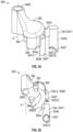
- the transfer members 754 may be attached to or integrally formed with a main body 757 of the implant 752.
- each of the transfer members 754 may be integrally formed with an augment body 761 of the augment 760 such that a position of each of the transfer members 654 is fixed relative to the augment body 761.
- Each of the transfer members 754 may include a first portion 754A and a second portion 754B.
- the first portion 754A may extend radially outward from a periphery of the augment body 761 relative to the axis X.
- the second portion 754B may extend axially between the first portion 754A and a terminal end portion 754T relative to the axis X.
- the terminal end portion 754T and/or another surface of the second portion 754B may be configured to abut bone B or other tissue adjacent the implant 752, as illustrated in Figure 47A .
- a surgeon or user may position the implant 752 based on a position of the transfer members 754 relative to the bone B such that the implant 752 is set at a fixed position and orientation specified in a predetermined surgical plan.
- Each of the transfer members 754 may be coupled to the augment 760 or another portion of the implant 752, such as the baseplate 758, at a respective breakable (e.g., frangible or severable) connection 772.
- Various techniques may be utilized to establish the breakable connection 772.
- the breakable connection 772 may be established such that the base portion 754D is positioned inwardly of an outer periphery of the baseplate 758, as illustrated in Figure 42 , which may reduce interaction between the base portion 754D and surrounding tissue subsequent to severing the breakable connection 772.
- Each transfer member 754 may include an interface 754I ( Figures 39-40 and 43-44 ).
- the interface 754I may be dimensioned to engage tooling T, as illustrated in Figure 47E .
- An interface axis IA may extend through the interface 754I.
- the second portion 754B may be dimensioned to extend along the interface axis IA.
- the breakable connection 772 may be configured to sever in response to movement of the second portion 754B of the transfer member 754 in a third direction D3 and/or a fourth direction D4 relative to axis X ( Figure 41 ).
- the third direction D3 may be in a direction generally towards the baseplate 658
- the fourth direction D4 may be in a direction generally away from the baseplate 658.
- a severed state of the breakable connections 722' is illustrated by the assembly 750' of Figures 45-46 .
- the transfer members 754 may be configured at step 198K.
- Step 198K may include integrally forming the transfer members 754 with the implant 652 based on one or more dimensions and other parameters established at step 198G subsequent to establishing the surgical plan at step 198J.
- Each of the transfer members 754 may be coupled to the implant 752 at a respective breakable connection 772.
- the implant 752 may be positioned according to the transfer members 754 at step 1980. Positioning the implant 752 may occur such that the rear face 761B or another surface of the augment 760 contacts the bone B or other tissue at the surgical site S. Step 1980 may occur such that the rear face 761B of the augment 760 substantially follows a surface contour of the bone B (see, e.g., Figures 47A and 47C ) based on a predetermined surgical plan, which may be established or updated at step 198J. The implant 752 may be positioned such that a portion of the transfer members 754 may overhang a periphery of the bone B, as illustrated in Figure 47C .
- one or more positioning objects such as a guide pin GP may be positioned to establish a predetermined position and/or orientation of the implant 752 based on the predetermined surgical plan.
- the guide pin GP may be positioned in the central aperture 758C by moving the guide pin GP in the direction D1, through the augment 760 and then into the bone B.
- Step 198S the transfer members 754 may be removed from the implant 752.
- Step 198S may include moving the tooling T along the respective interface axis IA and into engagement with each of the transfer members 754 at the interface 754I.
- Step 198S may include severing each of the breakable connections 772 in response to causing the tooling T to apply a predetermined quantity of torque or force to the respective transfer member 754 at the interface 754I, such as in the first rotational direction RD1 or one of the directions D3, D4 ( Figure 42 ).
- a severed state of the assembly 750' and breakable connections 772' is illustrated in Figures 45-46 and 47F .
- the tooling T may include a retention feature to secure the severed transfer member 754' for limiting separation of the transfer member 754' from the tooling T subsequent to the severing, which can improve removal of the transfer member 754' from the surgical site.
- exemplary retention features may include a grasper (e.g., a set of jaws) that interfaces with a periphery of the transfer member 754, a ball plunger configuration, or a ridge in a socket of the interface 754I that engages a protrusion along an end portion of the tooling T in response to rotation of the tooling T.
- Figures 48-52 illustrate a method of forming an orthopaedic implant assembly in a flowchart 896.
- the assembly may be utilized to perform an arthroplasty for restoring functionality to any of the joints disclosed herein.
- the method may be utilized with the planning system 20 to form any of the implant assemblies disclosed herein, including the assemblies 150, 250, 350, 450, 550, 650, 750 and/or 950, according to a predetermined (e.g., preoperative) surgical plan, which may be established according to any of the techniques disclosed herein.
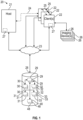
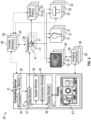
- the planning system 20 and any of associated modules may be configured to execute each of the steps of the method 896.
- a predetermined surgical plan may be established.
- the surgical plan may include one or more dimensions associated with one or more transfer members relative to a surface profile of tissue such as bone of a respective patient.
- the surgical plan may be established utilizing any of the techniques utilized herein, including the planning system 20 and step 198J of the method 198.
- Step 896A may include setting or determining one or more positioning parameters at step 896B.
- the positioning parameters may include any of the parameters disclosed herein, including a virtual position VP, virtual axis VA and/or contact point(s) CP determined at step 198G of the method 198.
- Step 896A may include accessing one or more records 41 in the database 29 associated with one or more transfer model(s) 48, implant model(s) 32 and/or surgical plan(s) 33 ( Figure 2 ).
- the method may utilize a printing assembly 990 to form the assembly 950.
- the printing assembly 990 may incorporate a three-dimensional (3D) printing head 990P coupled to a controller 990C.
- the printing head 990P may be positioned relative to a substrate 992 to form the assembly 950 (substrate 992 shown in dashed lines for illustrative purposes).
- the controller 990C may be operable to obtain coordinate information corresponding to a predetermined geometry of the assembly 950 and may be operable to command the printing head 990P to perform a series of passes to form successive layers of material on the substrate 992.
- the printing assembly 990 may be operable to form the assembly 950 utilizing any of the materials disclosed herein, including metallic and/or non-metallic materials. Three-dimensional printers are known, but utilization of three-dimensional printers to form the disclosed implant assemblies is not known.
- the printing assembly 990 may print or otherwise form a portion of a main body 957 of an implant 952 on the substrate 992 at step 896C.
- the main body 957 may include a baseplate 958 and augment 960 extending from the baseplate 958.
- the substrate 992 may be separate and distinct from the implant 952.
- the substrate 992 is a prefabricated portion of the implant 952, such as the baseplate 958.
- the baseplate 958 may include a plate body 959 extending between a first (e.g., front) face 959A and a second (e.g., rear) face 959B along a longitudinal (e.g., central) axis X of the implant 952.
- step 896C may include printing the plate body 959 of the baseplate 958 to establish one or more apertures.
- the apertures may include a central aperture 958C and one or more peripheral apertures 958P and other apertures 958A extending between the front face 959A and rear face 959B of the plate body 959.
- Step 896C may include printing or otherwise forming an augment 960 including an augment body 961 onto the rear face 959B of the baseplate 958. Step 896C may occur such that that the augment 960 may extend outwardly from the baseplate 958.
- the augment body 961 may include a second (e.g., rear) face 961B dimensioned to contact bone.
- the rear face 961B and/or another surface of the augment 960 may be dimensioned to substantially follow a surface contour of the bone based on a predetermined surgical plan.
- Step 896C may including printing or otherwise forming the portion of the main body 957 to establish one or more passages 960P.
- the passages 960P may extend through the augment body 961.
- the passages 960P may be at least partially axially aligned with a respective one of the central aperture 958C and peripheral apertures 958P and may be dimensioned to receive a respective fastener F to secure the implant 952 to bone, as illustrated in Figure 53 .
- Step 896C may include printing one or more tubular members 960T to establish the passages 960P (see Figure 53 ).
- Step 896C may include printing a portion of the augment body 961 to at least partially surround the tubular members 960T. In some implementations, the tubular members 960T are omitted and the augment body 961 establishes the passages 960P.
- the augment body 961 may be substantially solid or may include a porous scaffold that at least partially surrounds the tubular members 960T.
- the scaffold may establish an external surface of the augment 960.
- the method may include printing or otherwise forming one or more transfer members 954 such that the transfer members 954 are coupled to the implant 952.
- Step 896D may include integrally forming the transfer members 954 with the augment 960 or another portion of the main body 957 of the implant 952 based on the dimension(s) and/or other parameters associated with the surgical plan established at step 896A.
- Each of the transfer members 954 may include a respective contact surface 954CS.
- the contact surface 954CS may include any of the geometries disclosed herein, including a patient-specific or non-patient specific geometry.
- Step 896D may include forming the contact surface 954CS to substantially follow the surface profile of a bone based on the surgical plan (see, e.g., contact surface 354CS of Figure 26 ).
- the method may include printing or otherwise forming one or more breakable connections 972 to couple respective transfer members 954 to the implant 952 at step 896E.
- Step 896E may be separately performed, or may be concurrently performed with steps 896C and/or 986D.
- the breakable connections 972 can include any of the breakable connections disclosed herein.
- Each breakable connection 972 may be integrally formed with and interconnect the respective transfer members 954 to a wall of the main body 957 of the implant 952.
- Step 896D may include printing or otherwise forming an interface 954I associated with the transfer member 954.
- Each breakable connection 972 may be formed at step 896E such that the breakable connection 972 severs in response to a predetermined quantity of torque or force applied to the interface 954I of the respective transfer member 954.
- the predetermined quantity of torque or force may be established by one or more dimensions or parameters set or established at step 896B.
- Various techniques may be utilized to establish each breakable connection 972.
- the breakable connections 972 may be established by a reduced thickness, scoring, perforations, and/or different material compositions (e.g., different densities), etc., to facilitate severing the transfer members 954 from the main body 957 of the implant 952.
- a remainder of the implant 952 may be printed or otherwise formed at step 896F.
- Step 896F may include printing or otherwise forming a reminder of the main body 957 of the implant 952 including a remainder of the augment 960.
- Steps 896C-896F may be performed such that substantially all portions of the assembly 950 are printed or otherwise formed together to establish a monolithic or unitary component.
- steps 896C-896F may be performed such that at least the baseplate 958, augment 960 and transfer members 954 are printed or integrally formed together to establish a monolithic or unitary component.
Landscapes
- Health & Medical Sciences (AREA)
- Life Sciences & Earth Sciences (AREA)
- Engineering & Computer Science (AREA)
- Surgery (AREA)
- Public Health (AREA)
- General Health & Medical Sciences (AREA)
- Biomedical Technology (AREA)
- Heart & Thoracic Surgery (AREA)
- Veterinary Medicine (AREA)
- Animal Behavior & Ethology (AREA)
- Orthopedic Medicine & Surgery (AREA)
- Oral & Maxillofacial Surgery (AREA)
- Transplantation (AREA)
- Nuclear Medicine, Radiotherapy & Molecular Imaging (AREA)
- Molecular Biology (AREA)
- Medical Informatics (AREA)
- Cardiology (AREA)
- Vascular Medicine (AREA)
- Dentistry (AREA)
- Robotics (AREA)
- Physics & Mathematics (AREA)
- Geometry (AREA)
- Manufacturing & Machinery (AREA)
- Physical Education & Sports Medicine (AREA)
- Prostheses (AREA)
- Surgical Instruments (AREA)
Claims (13)
- Guide de transfert (56) pour une procédure orthopédique comprenant :un corps de guidage (62) configuré pour être couplé à un implant (52) ; etun ou plusieurs éléments de transfert (54) s'étendant depuis le corps de guidage (62), les un ou les plusieurs éléments de transfert (54) étant configurés pour être en contact avec le tissu,dans lequel les un ou plusieurs éléments de transfert (54) comportent une pluralité d'éléments de transfert (54) répartis circonférentiellement autour d'une périphérie du corps de guidage,caractérisé en ce que chacun des éléments de transfert (54) comporte une première portion (154A) s'étendant radialement vers l'extérieur à partir du corps de guidage (62) et une deuxième portion (154B) s'étendant axialement à partir de la première portion (154A), et la deuxième portion (154B) est configurée pour être en contact avec le tissu, dans lequel chacun des éléments de transfert (54) est mobile axialement par rapport au corps de guidage (62).
- Guide de transfert (56) selon la revendication 1, dans lequel le corps de guidage (62) comporte un passage (160P) dimensionné pour recevoir au moins partiellement une broche de guidage (GP) pouvant être insérée dans l'os.
- Guide de transfert (56) selon la revendication 1, dans lequel les un ou plusieurs éléments de transfert (54) peuvent être positionnés par rapport au corps de guidage (62) sur la base d'un plan chirurgical prédéterminé.
- Guide de transfert (56) selon la revendication 1, dans lequel chacun des éléments de transfert (54) comporte une troisième portion (154C) qui s'étend à partir de la première portion (154A), la troisième portion (154C) pouvant être déplacée en translation le long d'une fente respective établie dans la périphérie du corps de guidage (62) pour régler une position de la portion d'extrémité terminale (154T) par rapport au corps de guidage (62).
- Guide de transfert (56) selon la revendication 1, dans lequel la première portion (154A) et la deuxième portion (154B) établissent une géométrie essentiellement en forme de L.
- Ensemble pour une procédure orthopédique comprenant :un implant (52) configuré pour venir en butée contre l'os ; etun guide de transfert (56) selon la revendication 1,dans lequel les un ou plusieurs éléments de transfert (54) sont configurés pour être en contact avec l'os.
- Ensemble selon la revendication 6, dans lequel l'ensemble comporte l'une des options suivantes :a) le corps de guidage (62) comporte un passage (160P) dimensionné pour recevoir au moins partiellement une broche de guidage (GP) pouvant être insérée dans l'os pour régler une position de l'implant (52),b) les un ou plusieurs éléments de transfert (54) sont positionnés par rapport au corps de guidage (62) sur la base d'un plan chirurgical prédéterminé,
- Ensemble selon la revendication 6, dans lequel l'implant (52) comporte une plaque de base et un élément d'augmentation s'étendant depuis la plaque de base par rapport à un axe, et l'élément d'augmentation est dimensionné pour être en contact avec l'os.
- Ensemble selon la revendication 8, dans lequel l'ensemble comporte l'une des options suivantes :a) les un ou plusieurs éléments de transfert (54) sont dimensionnés pour être au moins partiellement alignés axialement avec l'élément d'augmentation par rapport à l'axe,b) l'élément d'augmentation comporte un corps d'augmentation s'étendant entre une première face et une deuxième face, la première face s'étendant le long de la plaque de base, et la deuxième face étant dimensionnée pour suivre essentiellement un contour de l'os,c) le corps de guidage (62) comporte des premiers filets qui s'accouplent avec des deuxièmes filets le long de la plaque de base pour fixer mécaniquement le guide de transfert (56) à l'implant (52).
- Ensemble selon la revendication 8, dans lequel :la plaque de base comporte une ouverture centrale et une pluralité d'ouvertures périphériques réparties circonférentiellement autour de l'ouverture centrale, chacune des ouvertures périphériques étant dimensionnée pour recevoir un élément de fixation respectif pour arrimer l'implant (52) à l'os ; etle guide de transfert (56) comporte un élément d'alignement, et l'élément d'alignement est dimensionné pour pouvoir être inséré dans une ouverture le long de la plaque de base afin de limiter la rotation relative entre le guide de transfert (56) et l'implant (52), etdans lequel le corps de guidage (62) peut comporter un passage (160P) configuré pour être aligné avec l'ouverture centrale dans une position installée, et le passage (160P) est dimensionné pour recevoir au moins partiellement une broche de guidage (GP) pouvant être insérée à travers l'ouverture centrale et jusque dans l'os pour régler une position de l'implant (52).
- Ensemble selon la revendication 6, dans lequel les un ou plusieurs éléments de transfert (54) sont mobiles entre une première position et une deuxième position.
- Ensemble selon la revendication 11, dans lequel :l'implant (52) comporte une plaque de base et un élément d'augmentation s'étendant depuis la plaque de base par rapport à un axe, et l'élément d'augmentation est dimensionné pour être en contact avec l'os ;la plaque de base comporte une ouverture centrale et une pluralité d'ouvertures périphériques réparties circonférentiellement autour de l'ouverture centrale, chacune des ouvertures périphériques étant dimensionnée pour recevoir un élément de fixation respectif pour arrimer l'implant (52) à l'os ;le corps de guidage (62) comporte une caractéristique de couplage au moins partiellement recevable dans l'ouverture centrale pour arrimer le guide de transfert (56) à l'implant (52) ; etle guide de transfert (56) comporte un élément d'alignement dimensionné pour pouvoir être inséré jusque dans une ouverture dans la plaque de base afin de limiter la rotation relative entre le guide de transfert (56) et l'implant (52).
- Ensemble selon la revendication 12,
dans lequel la caractéristique de couplage comporte des premiers filets qui s'accouplent avec des deuxièmes filets le long de l'ouverture centrale pour fixer mécaniquement le guide de transfert (56) à l'implant (52).
Priority Applications (1)
| Application Number | Priority Date | Filing Date | Title |
|---|---|---|---|
| EP25184707.5A EP4595929A3 (fr) | 2021-04-27 | 2022-04-14 | Systèmes d'implant orthopédique comprenant des éléments de transfert pour transfert de plan |
Applications Claiming Priority (2)
| Application Number | Priority Date | Filing Date | Title |
|---|---|---|---|
| US202163180239P | 2021-04-27 | 2021-04-27 | |
| PCT/US2022/024795 WO2022231853A1 (fr) | 2021-04-27 | 2022-04-14 | Systèmes d'implant orthopédique comprenant des caractéristiques de transfert et procédés de transfert de plan |
Related Child Applications (1)
| Application Number | Title | Priority Date | Filing Date |
|---|---|---|---|
| EP25184707.5A Division EP4595929A3 (fr) | 2021-04-27 | 2022-04-14 | Systèmes d'implant orthopédique comprenant des éléments de transfert pour transfert de plan |
Publications (3)
| Publication Number | Publication Date |
|---|---|
| EP4329677A1 EP4329677A1 (fr) | 2024-03-06 |
| EP4329677B1 true EP4329677B1 (fr) | 2025-07-02 |
| EP4329677C0 EP4329677C0 (fr) | 2025-07-02 |
Family
ID=81579814
Family Applications (2)
| Application Number | Title | Priority Date | Filing Date |
|---|---|---|---|
| EP22720870.9A Active EP4329677B1 (fr) | 2021-04-27 | 2022-04-14 | Systèmes d'implant orthopédique comprenant des caractéristiques de transfert de plan |
| EP25184707.5A Pending EP4595929A3 (fr) | 2021-04-27 | 2022-04-14 | Systèmes d'implant orthopédique comprenant des éléments de transfert pour transfert de plan |
Family Applications After (1)
| Application Number | Title | Priority Date | Filing Date |
|---|---|---|---|
| EP25184707.5A Pending EP4595929A3 (fr) | 2021-04-27 | 2022-04-14 | Systèmes d'implant orthopédique comprenant des éléments de transfert pour transfert de plan |
Country Status (6)
| Country | Link |
|---|---|
| US (2) | US12256997B2 (fr) |
| EP (2) | EP4329677B1 (fr) |
| JP (2) | JP7723115B2 (fr) |
| CN (1) | CN117279596A (fr) |
| CA (1) | CA3216633A1 (fr) |
| WO (1) | WO2022231853A1 (fr) |
Families Citing this family (5)
| Publication number | Priority date | Publication date | Assignee | Title |
|---|---|---|---|---|
| EP4553847A3 (fr) | 2013-10-10 | 2025-08-20 | Stryker European Operations Limited | Procédés, systèmes et dispositifs pour guides et implants chirurgicaux d'épaule pré-opératoires planifiés |
| WO2015068035A1 (fr) | 2013-11-08 | 2015-05-14 | Imascap | Méthodes, systèmes et dispositifs pour implants glénoïdiens adaptatifs à planification pré-opératoire |
| US10405993B2 (en) | 2013-11-13 | 2019-09-10 | Tornier Sas | Shoulder patient specific instrument |
| EP4629912A1 (fr) * | 2023-01-06 | 2025-10-15 | Arthrex, Inc. | Guides de transfert orthopédiques |
| US20250359874A1 (en) * | 2024-05-24 | 2025-11-27 | Arthrex, Inc. | Patient-specific orthopaedic transfer guides and associated methods of repair |
Citations (2)
| Publication number | Priority date | Publication date | Assignee | Title |
|---|---|---|---|---|
| WO2012024288A2 (fr) * | 2010-08-16 | 2012-02-23 | Smith & Nephew, Inc. | Outil d'alignement acétabulaire adapté à un patient |
| US10433983B1 (en) * | 2019-04-11 | 2019-10-08 | Arthrex, Inc. | Adjustable pin setting targeter device |
Family Cites Families (74)
| Publication number | Priority date | Publication date | Assignee | Title |
|---|---|---|---|---|
| JPH03261473A (ja) * | 1990-03-13 | 1991-11-21 | Yanmar Diesel Engine Co Ltd | 人工骨インプラント |
| FR2749753B1 (fr) | 1996-06-14 | 1998-12-24 | Mosseri Raphael | Prothese totale de hanche destinee a etre posee par voie endo-articulaire et son dispositif ancillaire |
| US7635390B1 (en) | 2000-01-14 | 2009-12-22 | Marctec, Llc | Joint replacement component having a modular articulating surface |
| US6395005B1 (en) | 2000-04-14 | 2002-05-28 | Howmedica Osteonics Corp. | Acetabular alignment apparatus and method |
| DE10129490A1 (de) | 2001-06-21 | 2003-01-02 | Helmut Mueckter | Implantierbare Schraube zur Stabilisierung einer Gelenkverbindung oder eines Knochenbruches |
| US8010180B2 (en) | 2002-03-06 | 2011-08-30 | Mako Surgical Corp. | Haptic guidance system and method |
| US8070820B2 (en) | 2003-10-08 | 2011-12-06 | Biomet Manufacturing Corp. | Shoulder implant assembly |
| US8303665B2 (en) | 2004-06-15 | 2012-11-06 | Tornier Sas | Glenoidal component, set of such components and shoulder prosthesis incorporating such a glenoidal component |
| EP2762107B1 (fr) | 2006-01-20 | 2017-11-29 | Zimmer Technology, Inc. | Système d'arthroplastie de l'épaule |
| US8603180B2 (en) | 2006-02-27 | 2013-12-10 | Biomet Manufacturing, Llc | Patient-specific acetabular alignment guides |
| JP5180953B2 (ja) | 2006-03-23 | 2013-04-10 | イグザクテック・インコーポレイテッド | 逆型肩関節用浅窩プレートおよびプロテーゼ |
| US8398645B2 (en) | 2007-09-30 | 2013-03-19 | DePuy Synthes Products, LLC | Femoral tibial customized patient-specific orthopaedic surgical instrumentation |
| US8267938B2 (en) | 2007-11-01 | 2012-09-18 | Murphy Stephen B | Method and apparatus for determining acetabular component positioning |
| US8801725B2 (en) | 2008-03-10 | 2014-08-12 | Zimmer Orthobiologics, Inc. | Instruments and methods used when repairing a defect on a tissue surface |
| US8864838B2 (en) * | 2008-03-14 | 2014-10-21 | The Cleveland Clinic Foundation | Acetabular cup buttress |
| US8747418B2 (en) | 2008-08-15 | 2014-06-10 | Monteris Medical Corporation | Trajectory guide |
| US8992538B2 (en) | 2008-09-30 | 2015-03-31 | DePuy Synthes Products, Inc. | Customized patient-specific acetabular orthopaedic surgical instrument and method of use and fabrication |
| US8632597B2 (en) | 2008-12-23 | 2014-01-21 | DePuy Synthes Products, LLC | Rotatable reverse metaglene |
| US9078755B2 (en) | 2009-02-25 | 2015-07-14 | Zimmer, Inc. | Ethnic-specific orthopaedic implants and custom cutting jigs |
| US8702717B2 (en) | 2009-07-31 | 2014-04-22 | Zimmer Gmbh | Glenoid alignment tool |
| US8696680B2 (en) | 2009-08-11 | 2014-04-15 | The Cleveland Clinic Foundation | Method and apparatus for insertion of an elongate pin into a surface |
| EP2525736A4 (fr) | 2010-01-22 | 2013-08-21 | Prec Through Imaging Llc | Système et procédé d'implantation dentaire |
| BR112012029287A2 (pt) * | 2010-05-18 | 2016-07-26 | Smith & Nephew Inc | sistemas de revisão de implantes e prótese de quadril |
| US20120276509A1 (en) | 2010-10-29 | 2012-11-01 | The Cleveland Clinic Foundation | System of preoperative planning and provision of patient-specific surgical aids |
| US9717508B2 (en) | 2010-10-29 | 2017-08-01 | The Cleveland Clinic Foundation | System of preoperative planning and provision of patient-specific surgical aids |
| US9877735B2 (en) * | 2010-10-29 | 2018-01-30 | The Cleveland Clinic Foundation | System and method for assisting with attachment of a stock implant to a patient tissue |
| US9226830B2 (en) | 2011-03-18 | 2016-01-05 | DePuy Synthes Products, Inc. | Device and method for retroversion correction for shoulder arthroplasty |
| WO2012154914A1 (fr) | 2011-05-11 | 2012-11-15 | The Cleveland Clinic Foundation | Génération d'instruments spécifiques pour un patient pour utilisation en tant qu'accessoires chirurgicaux |
| CA2837872A1 (fr) | 2011-06-03 | 2012-12-06 | Smith & Nephew, Inc. | Guide de prothese comprenant des caracteristiques appariees a un patient |
| US10925653B2 (en) | 2011-07-15 | 2021-02-23 | Globus Medical, Inc. | Screw implants for bone fusion |
| US20130245632A1 (en) | 2011-09-13 | 2013-09-19 | The Cleveland Clinic Foundation | Method and apparatus for insertion of an elongate pin into a surface |
| US8926627B2 (en) | 2011-09-13 | 2015-01-06 | The Cleveland Clinic Foundation | Apparatus and method for transferring predetermined spatial positioning information to an adjustable tool |
| WO2013103676A1 (fr) | 2012-01-04 | 2013-07-11 | The Cleveland Clinic Foundation | Appareil et procédé destinés à dicter au moins un parmi un emplacement souhaité et une trajectoire souhaitée pour associer un repère à des tissus de patient |
| US20130261751A1 (en) | 2012-03-27 | 2013-10-03 | Kyle E. Lappin | Reverse shoulder orthopaedic implant having an elliptical glenosphere component |
| AU2013243557A1 (en) | 2012-04-04 | 2014-10-09 | Smith & Nephew, Inc. | Surgical guide with intraoperative depth feedback |
| US9421103B2 (en) | 2012-04-05 | 2016-08-23 | Orthohelix Surgical Designs, Inc. | Lateral ankle fusion plate system and jig, and method for use therewith |
| US9033990B2 (en) | 2012-04-10 | 2015-05-19 | The Cleveland Clinic Foundation | Directed structure placement guide |
| US20150105696A1 (en) | 2012-05-23 | 2015-04-16 | Accelerated Orthopedic Technologies, Inc. | Instruments, Methods and Systems for Harvesting and Implanting Graft Materials |
| FR2997285B1 (fr) | 2012-10-26 | 2014-12-26 | Aston Medical | Gabarit de pose d'un 'implant d'articulation d'une prothese d'epaule sur une tete humerale |
| WO2014089291A1 (fr) * | 2012-12-05 | 2014-06-12 | Smith & Nephew, Inc. | Systèmes de guides orthopédiques et procédés |
| US9579107B2 (en) | 2013-03-12 | 2017-02-28 | Biomet Manufacturing, Llc | Multi-point fit for patient specific guide |
| US9498233B2 (en) | 2013-03-13 | 2016-11-22 | Biomet Manufacturing, Llc. | Universal acetabular guide and associated hardware |
| WO2014159984A1 (fr) | 2013-03-13 | 2014-10-02 | University Of Cincinnati | Ensembles spécifiques au patient, gabarits et procédés pour un système personnalisé d'arthroplastie de hanche totale |
| US9693785B2 (en) | 2013-07-02 | 2017-07-04 | Inova Health System | Device for a patient-specific acetabulum reaming and cup positioning guide |
| US10405993B2 (en) | 2013-11-13 | 2019-09-10 | Tornier Sas | Shoulder patient specific instrument |
| EP3777777B1 (fr) | 2014-01-03 | 2023-04-05 | Howmedica Osteonics Corp. | Implant glénoïde pour une prothèse d'épaule |
| US11026810B2 (en) | 2014-03-07 | 2021-06-08 | Biomet Manufacturing, Llc | Prosthesis alignment system |
| US10813774B2 (en) | 2014-03-07 | 2020-10-27 | Biomet Manufacturing, Llc | Subject contacting plate |
| US10357378B2 (en) | 2014-07-22 | 2019-07-23 | Zimmer, Inc. | Devices and methods for trochanteric osteotomy |
| US9844440B2 (en) | 2014-08-14 | 2017-12-19 | Biomet Manufacturing, Llc | Glenoid implant |
| US9826994B2 (en) | 2014-09-29 | 2017-11-28 | Biomet Manufacturing, Llc | Adjustable glenoid pin insertion guide |
| US9931168B2 (en) | 2015-01-12 | 2018-04-03 | Biomet Manufacuturing. LLC | Plan implementation |
| CN107205783B (zh) | 2015-02-02 | 2020-04-14 | 奥尔索夫特无限责任公司 | 髋臼边缘数字化装置和方法 |
| AU2016250842B2 (en) | 2015-04-24 | 2020-05-07 | Biomet Manufacturing, Llc | Patient-specific augmented glenoid systems |
| WO2016191725A1 (fr) | 2015-05-28 | 2016-12-01 | Zimmer, Inc. | Système et procédé de greffe osseuse spécifique au patient |
| US10070928B2 (en) | 2015-07-01 | 2018-09-11 | Mako Surgical Corp. | Implant placement planning |
| EP3319559B1 (fr) | 2015-07-08 | 2024-09-25 | Howmedica Osteonics Corp. | Systèmes d'épaule inversés |
| US10028803B2 (en) | 2015-09-17 | 2018-07-24 | Arthrex, Inc. | Tool setting device and method of transferring scaled setting information to a tool |
| US11090161B2 (en) | 2016-03-25 | 2021-08-17 | Howmedica Osteonics Corp. | Surgical instrumentation assembly, set and surgical shoulder repair method |
| KR102634074B1 (ko) | 2016-08-01 | 2024-02-05 | 이그잭테크, 인코포레이티드 | 초기 고정, 골절 재건, 및 관절 생체역학을 개선할 수 있는 모듈형 부착물들을 갖는 플랫폼 rtsa 관절와 보철물 |
| US10925755B2 (en) | 2016-08-17 | 2021-02-23 | Arizona Board Of Regents On Behalf Of Arizona State University | Osseointegratable prosthetic device and manufacturing method |
| US10945853B2 (en) | 2016-09-19 | 2021-03-16 | Smith & Nephew, Inc. | Glenoid implant and method of use thereof |
| US11033394B2 (en) | 2016-10-25 | 2021-06-15 | Institute for Musculoskeletal Science and Education, Ltd. | Implant with multi-layer bone interfacing lattice |
| US10925658B2 (en) | 2017-04-21 | 2021-02-23 | Zimmer, Inc. | Guide wire alignment |
| EP3624737B1 (fr) * | 2017-05-19 | 2021-08-04 | Biomet Manufacturing, LLC | Instruments d'assemblage d'implant |
| EP3403617B1 (fr) | 2017-05-19 | 2020-03-18 | Tornier | Insert d'augmentation, prothèse d'épaule et kit comprenant l'insert d'augmentation |
| US11399851B2 (en) | 2017-07-11 | 2022-08-02 | Howmedica Osteonics Corp. | Guides and instruments for improving accuracy of glenoid implant placement |
| KR102053599B1 (ko) | 2017-08-31 | 2020-01-23 | 주식회사 코렌텍 | 환자 맞춤형 지그 모델링이 가능한 시뮬레이션 시스템 및 방법 |
| EP3498227B1 (fr) | 2017-12-12 | 2020-11-04 | Tornier | Composant de prothèse d'épaule, tel qu'un composant huméral ou un composant glénoïde, pour un patient et procédé de fabrication d'un tel composant de prothèse d'épaule pour un patient |
| WO2019245862A1 (fr) | 2018-06-19 | 2019-12-26 | Tornier, Inc. | Visualisation de plans chirurgicaux à modification peropératoire |
| US12102390B2 (en) | 2018-11-19 | 2024-10-01 | Intellijoint Surgical Inc. | System and method for pre-planning a procedure |
| WO2020255152A1 (fr) * | 2019-06-21 | 2020-12-24 | Dr Shah Manish | Gabarit pour guider la mise en place du composant glénoïdien de l'implant dans une arthroplastie de l'épaule |
| US11471290B2 (en) * | 2019-07-10 | 2022-10-18 | Howmedica Osteonics Corp. | Counter-torque revisable stemless shoulder implant |
| US10561411B1 (en) | 2019-07-26 | 2020-02-18 | Little Engine, LLC | Flush anchor snap-off apparatus |
-
2022
- 2022-04-14 EP EP22720870.9A patent/EP4329677B1/fr active Active
- 2022-04-14 CN CN202280031098.XA patent/CN117279596A/zh active Pending
- 2022-04-14 WO PCT/US2022/024795 patent/WO2022231853A1/fr not_active Ceased
- 2022-04-14 EP EP25184707.5A patent/EP4595929A3/fr active Pending
- 2022-04-14 CA CA3216633A patent/CA3216633A1/fr active Pending
- 2022-04-14 JP JP2023565956A patent/JP7723115B2/ja active Active
- 2022-04-21 US US17/725,586 patent/US12256997B2/en active Active
-
2025
- 2025-02-14 US US19/053,680 patent/US20250186124A1/en active Pending
- 2025-07-30 JP JP2025127633A patent/JP2025142340A/ja active Pending
Patent Citations (2)
| Publication number | Priority date | Publication date | Assignee | Title |
|---|---|---|---|---|
| WO2012024288A2 (fr) * | 2010-08-16 | 2012-02-23 | Smith & Nephew, Inc. | Outil d'alignement acétabulaire adapté à un patient |
| US10433983B1 (en) * | 2019-04-11 | 2019-10-08 | Arthrex, Inc. | Adjustable pin setting targeter device |
Also Published As
| Publication number | Publication date |
|---|---|
| JP2025142340A (ja) | 2025-09-30 |
| EP4329677A1 (fr) | 2024-03-06 |
| JP7723115B2 (ja) | 2025-08-13 |
| JP2024515799A (ja) | 2024-04-10 |
| US20250186124A1 (en) | 2025-06-12 |
| US20220338933A1 (en) | 2022-10-27 |
| EP4595929A3 (fr) | 2025-09-17 |
| EP4329677C0 (fr) | 2025-07-02 |
| EP4595929A2 (fr) | 2025-08-06 |
| WO2022231853A1 (fr) | 2022-11-03 |
| CN117279596A (zh) | 2023-12-22 |
| CA3216633A1 (fr) | 2022-11-03 |
| US12256997B2 (en) | 2025-03-25 |
Similar Documents
| Publication | Publication Date | Title |
|---|---|---|
| EP4329677B1 (fr) | Systèmes d'implant orthopédique comprenant des caractéristiques de transfert de plan | |
| US12114934B2 (en) | Automated arthroplasty planning | |
| US20230346397A1 (en) | System and method for association of a guiding aid with a patient tissue | |
| US11864837B2 (en) | System and methods for positioning bone cut guide | |
| US20240225858A1 (en) | Orthopaedic transfer guides and methods of repair | |
| US12433615B2 (en) | Orthopaedic systems, transfer guide assemblies, and methods of repair | |
| US20250057597A1 (en) | Orthopaedic implant systems and associated methods of fixation | |
| US20250359874A1 (en) | Patient-specific orthopaedic transfer guides and associated methods of repair |
Legal Events
| Date | Code | Title | Description |
|---|---|---|---|
| STAA | Information on the status of an ep patent application or granted ep patent |
Free format text: STATUS: UNKNOWN |
|
| STAA | Information on the status of an ep patent application or granted ep patent |
Free format text: STATUS: THE INTERNATIONAL PUBLICATION HAS BEEN MADE |
|
| PUAI | Public reference made under article 153(3) epc to a published international application that has entered the european phase |
Free format text: ORIGINAL CODE: 0009012 |
|
| STAA | Information on the status of an ep patent application or granted ep patent |
Free format text: STATUS: REQUEST FOR EXAMINATION WAS MADE |
|
| 17P | Request for examination filed |
Effective date: 20231115 |
|
| AK | Designated contracting states |
Kind code of ref document: A1 Designated state(s): AL AT BE BG CH CY CZ DE DK EE ES FI FR GB GR HR HU IE IS IT LI LT LU LV MC MK MT NL NO PL PT RO RS SE SI SK SM TR |
|
| STAA | Information on the status of an ep patent application or granted ep patent |
Free format text: STATUS: EXAMINATION IS IN PROGRESS |
|
| DAV | Request for validation of the european patent (deleted) | ||
| DAX | Request for extension of the european patent (deleted) | ||
| 17Q | First examination report despatched |
Effective date: 20240730 |
|
| GRAP | Despatch of communication of intention to grant a patent |
Free format text: ORIGINAL CODE: EPIDOSNIGR1 |
|
| STAA | Information on the status of an ep patent application or granted ep patent |
Free format text: STATUS: GRANT OF PATENT IS INTENDED |
|
| INTG | Intention to grant announced |
Effective date: 20250204 |
|
| GRAS | Grant fee paid |
Free format text: ORIGINAL CODE: EPIDOSNIGR3 |
|
| GRAA | (expected) grant |
Free format text: ORIGINAL CODE: 0009210 |
|
| STAA | Information on the status of an ep patent application or granted ep patent |
Free format text: STATUS: THE PATENT HAS BEEN GRANTED |
|
| AK | Designated contracting states |
Kind code of ref document: B1 Designated state(s): AL AT BE BG CH CY CZ DE DK EE ES FI FR GB GR HR HU IE IS IT LI LT LU LV MC MK MT NL NO PL PT RO RS SE SI SK SM TR |
|
| REG | Reference to a national code |
Ref country code: GB Ref legal event code: FG4D |
|
| REG | Reference to a national code |
Ref country code: CH Ref legal event code: EP |
|
| REG | Reference to a national code |
Ref country code: DE Ref legal event code: R096 Ref document number: 602022016887 Country of ref document: DE |
|
| REG | Reference to a national code |
Ref country code: IE Ref legal event code: FG4D |
|
| U01 | Request for unitary effect filed |
Effective date: 20250728 |
|
| U07 | Unitary effect registered |
Designated state(s): AT BE BG DE DK EE FI FR IT LT LU LV MT NL PT RO SE SI Effective date: 20250801 |
|
| PG25 | Lapsed in a contracting state [announced via postgrant information from national office to epo] |
Ref country code: IS Free format text: LAPSE BECAUSE OF FAILURE TO SUBMIT A TRANSLATION OF THE DESCRIPTION OR TO PAY THE FEE WITHIN THE PRESCRIBED TIME-LIMIT Effective date: 20251102 |
|
| PG25 | Lapsed in a contracting state [announced via postgrant information from national office to epo] |
Ref country code: NO Free format text: LAPSE BECAUSE OF FAILURE TO SUBMIT A TRANSLATION OF THE DESCRIPTION OR TO PAY THE FEE WITHIN THE PRESCRIBED TIME-LIMIT Effective date: 20251002 |
|
| PG25 | Lapsed in a contracting state [announced via postgrant information from national office to epo] |
Ref country code: HR Free format text: LAPSE BECAUSE OF FAILURE TO SUBMIT A TRANSLATION OF THE DESCRIPTION OR TO PAY THE FEE WITHIN THE PRESCRIBED TIME-LIMIT Effective date: 20250702 |
|
| PG25 | Lapsed in a contracting state [announced via postgrant information from national office to epo] |
Ref country code: GR Free format text: LAPSE BECAUSE OF FAILURE TO SUBMIT A TRANSLATION OF THE DESCRIPTION OR TO PAY THE FEE WITHIN THE PRESCRIBED TIME-LIMIT Effective date: 20251003 |
|
| PG25 | Lapsed in a contracting state [announced via postgrant information from national office to epo] |
Ref country code: CZ Free format text: LAPSE BECAUSE OF FAILURE TO SUBMIT A TRANSLATION OF THE DESCRIPTION OR TO PAY THE FEE WITHIN THE PRESCRIBED TIME-LIMIT Effective date: 20250702 |
|
| PG25 | Lapsed in a contracting state [announced via postgrant information from national office to epo] |
Ref country code: PL Free format text: LAPSE BECAUSE OF FAILURE TO SUBMIT A TRANSLATION OF THE DESCRIPTION OR TO PAY THE FEE WITHIN THE PRESCRIBED TIME-LIMIT Effective date: 20250702 |
|
| PG25 | Lapsed in a contracting state [announced via postgrant information from national office to epo] |
Ref country code: RS Free format text: LAPSE BECAUSE OF FAILURE TO SUBMIT A TRANSLATION OF THE DESCRIPTION OR TO PAY THE FEE WITHIN THE PRESCRIBED TIME-LIMIT Effective date: 20251002 |
|
| PG25 | Lapsed in a contracting state [announced via postgrant information from national office to epo] |
Ref country code: ES Free format text: LAPSE BECAUSE OF FAILURE TO SUBMIT A TRANSLATION OF THE DESCRIPTION OR TO PAY THE FEE WITHIN THE PRESCRIBED TIME-LIMIT Effective date: 20250702 |
|
| PG25 | Lapsed in a contracting state [announced via postgrant information from national office to epo] |
Ref country code: SM Free format text: LAPSE BECAUSE OF FAILURE TO SUBMIT A TRANSLATION OF THE DESCRIPTION OR TO PAY THE FEE WITHIN THE PRESCRIBED TIME-LIMIT Effective date: 20250702 |
|
| PGFP | Annual fee paid to national office [announced via postgrant information from national office to epo] |
Ref country code: GB Payment date: 20260223 Year of fee payment: 5 |
|
| U20 | Renewal fee for the european patent with unitary effect paid |
Year of fee payment: 5 Effective date: 20260310 |
|
| PG25 | Lapsed in a contracting state [announced via postgrant information from national office to epo] |
Ref country code: SK Free format text: LAPSE BECAUSE OF FAILURE TO SUBMIT A TRANSLATION OF THE DESCRIPTION OR TO PAY THE FEE WITHIN THE PRESCRIBED TIME-LIMIT Effective date: 20250702 |