EP4330027B1 - Vorrichtung zum formen einer faserigen vorform zur herstellung eines beschaufelten teils eines turbinenmotors - Google Patents
Vorrichtung zum formen einer faserigen vorform zur herstellung eines beschaufelten teils eines turbinenmotors Download PDFInfo
- Publication number
- EP4330027B1 EP4330027B1 EP22735515.3A EP22735515A EP4330027B1 EP 4330027 B1 EP4330027 B1 EP 4330027B1 EP 22735515 A EP22735515 A EP 22735515A EP 4330027 B1 EP4330027 B1 EP 4330027B1
- Authority
- EP
- European Patent Office
- Prior art keywords
- preform
- shell
- shells
- mould
- elements
- Prior art date
- Legal status (The legal status is an assumption and is not a legal conclusion. Google has not performed a legal analysis and makes no representation as to the accuracy of the status listed.)
- Active
Links
Images





Classifications
-
- B—PERFORMING OPERATIONS; TRANSPORTING
- B29—WORKING OF PLASTICS; WORKING OF SUBSTANCES IN A PLASTIC STATE IN GENERAL
- B29D—PRODUCING PARTICULAR ARTICLES FROM PLASTICS OR FROM SUBSTANCES IN A PLASTIC STATE
- B29D99/00—Subject matter not provided for in other groups of this subclass
- B29D99/0025—Producing blades or the like, e.g. blades for turbines, propellers, or wings
-
- B—PERFORMING OPERATIONS; TRANSPORTING
- B29—WORKING OF PLASTICS; WORKING OF SUBSTANCES IN A PLASTIC STATE IN GENERAL
- B29C—SHAPING OR JOINING OF PLASTICS; SHAPING OF MATERIAL IN A PLASTIC STATE, NOT OTHERWISE PROVIDED FOR; AFTER-TREATMENT OF THE SHAPED PRODUCTS, e.g. REPAIRING
- B29C33/00—Moulds or cores; Details thereof or accessories therefor
- B29C33/30—Mounting, exchanging or centering
-
- B—PERFORMING OPERATIONS; TRANSPORTING
- B29—WORKING OF PLASTICS; WORKING OF SUBSTANCES IN A PLASTIC STATE IN GENERAL
- B29B—PREPARATION OR PRETREATMENT OF THE MATERIAL TO BE SHAPED; MAKING GRANULES OR PREFORMS; RECOVERY OF PLASTICS OR OTHER CONSTITUENTS OF WASTE MATERIAL CONTAINING PLASTICS
- B29B11/00—Making preforms
- B29B11/14—Making preforms characterised by structure or composition
- B29B11/16—Making preforms characterised by structure or composition comprising fillers or reinforcement
-
- B—PERFORMING OPERATIONS; TRANSPORTING
- B29—WORKING OF PLASTICS; WORKING OF SUBSTANCES IN A PLASTIC STATE IN GENERAL
- B29L—INDEXING SCHEME ASSOCIATED WITH SUBCLASS B29C, RELATING TO PARTICULAR ARTICLES
- B29L2031/00—Other particular articles
- B29L2031/08—Blades for rotors, stators, fans, turbines or the like, e.g. screw propellers
Definitions
- the present invention relates to a device for shaping a fiber preform for producing a bladed part of a turbomachine, as well as a method using this device.
- the state of the art includes in particular the documents FR-A1-3 014 008 , FR-A1-3 029 134 , FR-B1-2 943 942 , FR-B1-3 022 829 , FR-B1-3 085 131 And FR-A1-3 046 404 , .
- composite materials are advantageous in the aeronautics industry in particular because these materials have interesting mechanical performances for relatively low masses.
- a process for manufacturing a composite part for the aeronautical industry which is well known to those skilled in the art, is the RTM molding process, the initials of which refer to the Anglo-Saxon acronym for Resin Transfer Molding.
- the first step is to weave the fibers to obtain a three-dimensional preform blank, then cut the blank to obtain a preform that has approximately the same shape as the bladed part to be obtained. This preform is then placed in a mold, which is closed.
- this mold has two functions or two successive uses.
- the mold is first used to shape the preform by hot compression. It is then placed under pressure and in an oven in order to compress the preform and stiffen it.
- the mold is then used to inject resin into the preform for impregnation.
- the resin is injected through a feed port in the mold, which is then placed in an oven to cause the resin to polymerize and harden.
- the bladed part is then removed from the mold and can undergo various successive operations, particularly finishing.
- This mold is also not suitable for performing other functions such as positioning and fixing a metal shield on a leading edge of the bladed part.
- the composite material of the bladed part is relatively fragile, and in particular sensitive to shocks, and it is known to protect it by means of a metal shield which is added and fixed on the leading edge of the bladed part.
- the shield can be attached to the blade in several ways.
- One way is to glue the shield to the bladed part, after the resin has cured.
- a second way to fix a shield to a bladed part is to fix the shield by co-molding with the fiber preform.
- the preform is placed in the mold and the shield is positioned or glued on the edge of the preform intended to form the leading edge of the blade.
- the injected resin impregnates the preform and comes into contact with the shield to ensure its joining to the blade after polymerization and curing.
- a film of glue can be interposed between the preform and the shield and is then intended to polymerize at the same time as the resin, which makes pairing easier and eliminates a thermal cycle on the finished part.
- the aforementioned mold of the current technique is not suitable for positioning the shield on the preform or for fixing it.
- the present invention proposes a solution to these problems which consists of proposing a device specifically adapted to the implementation of only one of the aforementioned functions, namely here the shaping of the preform, and which is capable of also carrying out the pairing of the metal shield to the leading edge of the preform.
- the device is specifically designed and optimized to carry out the shaping of the preform, this shaping being preferably carried out by compressing and heating the preform in the mold.
- the device according to the invention is further advantageously designed to allow the precise positioning of the metal shield on the leading edge of the preform.
- the various parts of the mold facilitate the assembly of the mold around the preform as well as the disassembly of the mold, and in particular the partial disassembly of the mold.
- the elements of the end shells can in fact be assembled and disassembled independently of the upper and lower shells.
- the elements of the side shell can also be assembled and disassembled independently, which allows access to the leading edge of the preform for positioning the shield.
- the convex curved surface of the lower shell is configured to be complementary to the concave side of the blade, called the intrados.
- the concave curved surface of the upper shell is configured to be complementary to the convex side of the blade, called the extrados.
- the method may comprise, before step a), a step 0) of inserting a mandrel, such as a block of foam, into an internal passage of the preform, this internal passage extending inside the blade and opening out at the platforms.
- a mandrel such as a block of foam
- the method may comprise, between sub-steps a1) and a2), an additional sub-step y) of installing a positioning member of the mandrel (block of foam) at each end of the preform, and between sub-steps a2) and a3), a sub-step z) of removal of these positioning members.
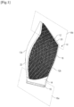
- FIG. 1 illustrates a bladed part 10 made of composite material for a turbomachine, this bladed part 10 being for example a fan blade or a rectifier blade of a secondary flow in the case of a dual-flow turbojet.
- the bladed part 10 comprises a blade 12.
- this blade 12 is connected by a stilt 14 to a foot 16 which has for example a dovetail shape and is shaped to be engaged in a cell of complementary shape of a rotor disk, in order to retain the blade on this disk.
- the blade 12 extends between two platforms 16a, 16b which extend substantially parallel to each other and perpendicular to an axis of elongation of the blade 14.
- the blade 12 comprises a leading edge 12a and a trailing edge 12b for the gases flowing into the turbomachine.
- the blade 12 has a curved or even twisted aerodynamic profile and comprises a lower surface 18 and an upper surface 20 extending between the leading edges 12a and trailing edges 12b.
- the blade 12 is made from a fiber preform obtained by three-dimensional weaving of fibers, for example carbon.
- the leading edge 12a of the blade is reinforced and protected by a metal shield 22 which is fixed on this leading edge 12a.
- the shield 22 is for example made of a nickel and cobalt-based alloy.
- the correct positioning of the shield 22 on the preform is achieved with a device 30 for shaping this preform, this shaping preferably being achieved by compression and heating.
- FIG. 1 An embodiment of the device 30 according to the invention is shown in figures 2 to 11 .
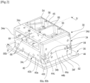
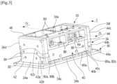
- Device 30 is shown in its entirety in figures 2 And 3 In the example shown, it has a general parallelepiped shape.
- THE figures 4 And 5 represent sectional views of the device 30 and show that it comprises at least one internal cavity 32 configured to receive the fiber preform of the or each bladed part 10 to be produced.
- this bladed part 10 is a stator blade. It can therefore be seen that the cavity 32 essentially comprises three parts or zones, a blade zone Z1 intended to receive the part of the preform forming the blade 12 of the bladed part 10, and two platform zones Z2, Z3 intended to receive the parts of the preform forming the platforms 16a, 16b of the bladed part 10.
- the device 30 essentially comprises a mold 34.
- this mold is presented on a flat support or a base 36, which is however optional.
- the mold 34 has a generally parallelepiped shape and comprises an upper face 34a, a lower face 34b and four lateral faces 34c-34f. faces 34a-34f are rectangular here.
- the mold 34 is placed flat on the base 36 by pressing its lower face 34b on this base 36.
- the side faces 34e, 34f are located on two opposite sides of the mold 34 and at the level of the platform zones Z2, Z3 of the cavity 32 (cf. Figure 5 ).
- the lateral faces 34c, 34d are located on two opposite sides of the mold 34 and at the level of the leading edges 12a and trailing edges 12b of the blade 12 respectively (cf. Figure 4 ).
- the mold 34 is obtained by assembling several parts to facilitate its assembly around the preform and to also facilitate the positioning and compacting of the preform while allowing access to the leading edge 12a of the preform for the positioning of the metal shield 22.
- the parts of the mold 34 are here formed by shells or shell elements which are nested within each other in order to define the cavity 32. As can be seen in the drawings, the cavity 32 is entirely delimited by the mold 34, which means that the mold 34 is configured to completely enclose the preform.
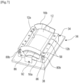
- the lower hull 38 is visible at figures 4 And 5 and mounted on the base 36 at the Figure 7
- This shell 38 forms a part of the lower end of the mold 34 and comprises a part of the face 34b and a lower part of the face 34d.
- the lower shell 38 defines a lower portion of the cavity 32 and includes an upper surface 48 having a convex curved section shape (cf. Figure 4 ) intended to be located on the side of the intrados 18 of the blade 12.
- the upper shell 46 forms a portion of the upper end of the mold 34 and includes a portion of the face 34a and an upper portion of the face 34d.
- the shell 46 defines an upper portion of the cavity 32 and includes a lower surface 52 having a concave curved sectional shape (cf. Figure 4 ) intended to be located on the side of the extrados 20 of the blade 12.
- the upper 46 and lower 38 shells are fixed to each other, for example, by screws 54 which pass through holes 56 in the upper shell and are screwed into threaded holes 58 in the lower shell (cf. figures 2 , 4 And 7 ).
- the upper 46 and lower 38 shells define a first side of the mold 34 and form between them a first groove 60 for forming the trailing edge 12b of the blade 12 ( Figure 4 ).
- the side hull 40 is visible at figures 2 to 4 in particular and forms a second side of the mold 34, namely the one which comprises the surface 34c located on the side of the leading edge 12a of the blade 12.
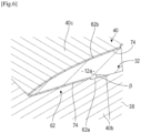
- the shell 40 forms a second groove 62 for forming the leading edge 12a of the blade ( figures 4 And 6 ).
- the side shell 40 is fixed to the lower 38 and upper 46 shells by screws 64 which pass through holes 66 of the side shell 40 and are screwed into threaded holes 68 of the lower 38 and upper 46 shells ( figures 2 to 4 And 11 ).
- the side shell 40 comprises three elements, respectively lower 40a, intermediate 40b and upper 40c, which are fixed independently and removably so as to be able to be dismantled and removed from the mold 34 without dismantling the upper 46 and lower 38 shells.
- first and second surfaces 70, 72 are inclined at an angle ⁇ relative to the horizontal. This angle ⁇ is greater than an angle ⁇ of inclination of the lower part 62a of the second groove 62, which is also measured relative to the horizontal.
- FIG. 6 which is a larger scale view of the second groove 62, shows that the lower 62a and upper 62b parts of this second groove 62 each define a step 74 for overcompacting the preform.
- the step 74 makes it possible to define an expected position of the shield to allow better pairing of the latter with the preform.
- the end shells 42, 44 are intended to delimit the platform zones Z2, Z3 of the cavity 32 with the lower 38 and upper 46 shells ( Figure 5 ).
- a first end shell 42 located on the left at the Figure 3 comprises the surface 34e and is formed by the assembly of three elements 42a, 42b, 42c.
- a second end shell 44 located on the right at the Figure 3 understand surface 34f and is formed by the assembly of three elements 44a, 44b, 44c.
- the intermediate shell member 42b, 44b of each of the end shells 42, 44 includes a projecting rib 76 configured to be engaged in an internal passage 78 of the preform;
- This intermediate shell element 42b, 44b may comprise indexing means 80a configured to cooperate with complementary means 80b of at least one of the lower 38, upper 46 and lateral 40 shells, as can be seen in figures 2 And 3
- indexing and complementary means 80a, 80b cooperate for example by interlocking or male-female engagement, and comprise for example fingers carried by the shell element 42b, 44b and notches formed on the lower shell 38.
- Each intermediate shell element 42b, 44b includes upper and lower ends shaped to fit without play into the corresponding ends of the upper 42c, 44c and lower 42a, 44a shell elements, respectively. These ends may further be shaped to provide keying during assembly and to avoid the assembly of one of the elements in place of another.
- each end shell 42, 44 are fixed by screws 82 which pass through holes 84 of these shell members and are screwed into threaded holes 86 of other hulls or hull elements.
- the figures show that at least certain faces 34a, 34c of the mold 34 have recesses 88 for lightening the mold. This is particularly the case, in the example shown, of the upper shell 46 which comprises recesses 88 on the upper face 34a (cf. figures 2 And 3 ), of the upper shell element 40c of the side shell 40 which also comprises recesses 88 on the side face 34c, and of the lower shell 38 which comprises recesses 88 on the lower face 34b (cf. Figure 4 ).
- the present invention also relates to a method for shaping a preform with a view to producing a bladed part of a turbomachine, using the device 30.
- the method may comprise a step 0) of inserting a mandrel, such as a block of foam 90, into the internal passage 78 of the preform, this internal passage 78 extending inside the blade and opening out at the platforms 16a, 16b.
- a mandrel such as a block of foam 90
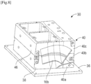
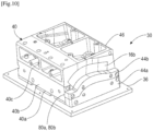
- Step a) of the process is illustrated in figures 7 to 10 notably.
- the method may comprise an additional sub-step y) of installing a positioning member 92 of the mandrel (foam block 90) at each of the ends of the preform.
- a positioning member 92 of the mandrel (foam block 90) is visible in the Figure 7 and can be placed or mounted on the base 36.
- These members 92 serve to hold the mandrel (block of foam 90) in position before the assembly and fixing of the upper shell 46. After fixing this upper shell 46, the blade 12 is held fixedly between the lower 38 and upper 46 shells and the mandrel (block of foam 90) is no longer likely to move in the passage 78.
- the members 92 are then no longer necessary and the method then comprises, between the sub-steps a2) and a3), a sub-step z) of removing these positioning members.
- the device 30 is closed in step b) in order to clamp the shells of the mold 34 against each other, and compact the preform.
- the assembly is placed in the oven in step c) to dry the preform and set the predetermined shape by shaping and compacting.
- the overcompaction mentioned in the above in relation to the Figure 6 makes it easier to mount the shield 22 on the leading edge 12a.
- This overcompaction can be determined so that the crushing and the additional reduction in thickness generated compensates for the thickness of the shield 22, the elastic return of the preform (when dismantling the shells), possibly the thickness of the glue film and sufficient clearance to allow the insertion of the shield.
- this reduction in thickness could also compensate for the thickness of the glue film or even the variation in thickness of this film.
- the blade 12 and the leading edge 12a may have a generally horizontal orientation, as shown in the drawings.
- the blade 12 and the leading edge could be oriented substantially vertically to facilitate mounting of the shield 22 on the leading edge.
- the dried and stiffened preform may be transferred to another mold for the purpose of injecting resin into the preform and solidifying the bladed part 10.
- the device according to the invention is advantageous insofar as it is adapted and optimized for shaping the preform and pairing the shield.
- it does not necessarily include sealing means such as than seals unlike a resin injection mold.
- sealing means such as than seals unlike a resin injection mold.
- it can be made of a lightweight or good thermal conductive material (to optimize the heating cycle), such as aluminum for example, so as to facilitate its handling.
- the device according to the invention could be used for the simultaneous manufacture of several bladed parts and could comprise a cavity for receiving several preforms or several separate cavities for receiving these preforms.
Landscapes
- Engineering & Computer Science (AREA)
- Mechanical Engineering (AREA)
- Structures Of Non-Positive Displacement Pumps (AREA)
Claims (14)
- Vorrichtung (30) zur Ausformung mindestens einer faserigen Vorform für die Herstellung eines beschaufelten Werkstückes (10) einer Turbomaschine, wobei diese Vorrichtung eine Form (34) umfasst, die aus mehreren ineinandergreifenden Werkstücken gebildet ist, wobei diese Form mindestens einen Innenhohlraum (32) definiert, der konfiguriert ist, um die Vorform aufzunehmen und um die Vorform vollständig zu umschließen, wobei dieser Hohlraum (32) dazu bestimmt ist, zwei Plattformzonen (Z2, Z3) und eine Schaufelzone (Z1) zu haben, die sich zwischen den beiden Plattformzonen erstreckt,
dadurch gekennzeichnet, dass die Form (34) mindestens umfasst:- eine untere Schale (38), die ein unteres Ende der Form (34) bildet und die eine gekrümmte, konvexe Oberfläche (48) der Schaufelzone (Z1) umfasst,- eine obere Schale (46), die ein oberes Ende der Form (34) bildet und die eine gekrümmte, konkave Oberfläche (52) des Schaufelteils (Z1) umfasst, wobei die obere und die untere Schale (46, 38) aneinander befestigt sind, eine erste Seite der Form definieren und zwischen sich eine erste Nut (60) zur Bildung einer Hinterkante (12b) der Schaufelzone (Z1) bilden,- eine seitliche Schale (40), die eine zweite Seite der Form (34) bildet, wobei diese zweite Seite der ersten Seite gegenüberliegt und eine zweite Nut (62) zur Bildung einer Vorderkante (12a) der Schaufelzone (Z1) bildet, und- Endschalen (42, 44), die sich an zwei gegenüberliegenden Enden der Form befinden und zwischen denen sich die untere Schale (38), die obere Schale (46) und die seitliche Schale (40) erstrecken, wobei diese Endschalen jeweils mindestens einen Teil der Plattformzonen (Z2, Z3) bilden,und dass jede der seitlichen Schale (40) und der Endschale (42, 44) drei Elemente umfasst, jeweils ein unteres (40a, 42a, 44a), ein mittleres (40b 42b, 44b) und ein oberes (40c, 42c, 44c), wobei die Elemente der seitlichen Schale (40) und der Endschale (42, 44) unabhängig und abnehmbar befestigt sind, so dass sie ohne Ausbau der oberen Schale (46) und der unteren Schale (38) ausgebaut und aus der Form entfernt werden können. - Ausformungsvorrichtung (30) nach dem vorstehenden Anspruch, wobei die drei Elemente der seitlichen Schale (40) umfassen:- ein unteres Schalenelement (40a), das sich unter der zweiten Nut (62) befindet und das eine erste obere Gleitoberfläche (70) umfasst,- ein Zwischenschalenelement (40b), das sich auf dem unteren Schalenelement (40a) befindet und das einen unteren Teil (62a) der zweiten Nut (62) definiert, wobei das Zwischenschalenelement (40b) eine zweite untere Gleitoberfläche (72) aufweist, die konfiguriert ist, um bei einem Ausbau des Zwischenschalenelements (40b) gleitend mit der ersten Oberfläche (70) zusammenzuwirken, und- ein oberes Schalenelement (40c), das sich auf dem Zwischenschalenelement (40b) befindet und das einen oberen Tei (62b) der zweiten Nut (62) definiert.
- Ausformungsvorrichtung (30) nach dem vorstehenden Anspruch, wobei die erste und die zweite Oberfläche (70, 72) um einen Winkel α in Bezug auf die Horizontale geneigt sind, wobei der Winkel α größer ist als ein Neigungswinkel β des unteren Teils (62b) der zweiten Nut (62), der ebenfalls in Bezug auf die Horizontale gemessen wird.
- Ausformungsvorrichtung (30) nach Anspruch 2 oder 3, wobei der untere Teil (62a) der zweiten Nut (62) und der obere Teil (62b) der zweiten Nut (62) jeweils eine Stufe (74) zum Überverdichten der Vorform definieren.
- Ausformungsvorrichtung (30) nach einem der vorstehenden Ansprüche, wobei die drei Elemente jeder der Endschalen (42, 44) umfassen:- ein unteres Schalenelement (42a, 44a), das mit der unteren Schale (38) einen unteren Teil der entsprechenden Plattformzone (Z2, Z3) definiert,- ein oberes Schalenelement (42c, 44c), das mit der oberen Schale (46) einen oberen Teil dieser Plattformzone (Z2, Z3) definiert, und- ein Zwischenschalenelement (42b, 44b), das zwischen dem unteren und dem oberen Schalenelement (42a, 44a, 42c, 44c) eingefügt ist und konfiguriert ist, um sich in die Verlängerung der Schaufelzone (Z1) zu erstrecken.
- Ausformungsvorrichtung (30) nach einem der vorstehenden Ansprüche, wobei das Zwischenschalenelement (42b, 44b) jeder der Endschalen (42, 44) eine vorstehende Rippe (76) umfasst, die konfiguriert ist, um mit einem inneren Durchgang (78) der Vorform in Eingriff zu kommen.
- Ausformungsvorrichtung (30) nach einem der vorstehenden Ansprüche, wobei das Zwischenschalenelement (42b, 44b) Indexierungsmittel (80a) umfasst, die konfiguriert sind, um mit komplementären Mitteln (80b) von mindestens einer der unteren Schale (38), der oberen Schale (46) und der seitlichen Schale (40) zusammenzuwirken.
- Ausformungsvorrichtung (30) nach einem der vorstehenden Ansprüche, wobei die Schalen und Schalenelemente der Form (34) durch Schrauben (54, 64, 82) befestigt sind, die durch Öffnungen (56, 66, 84) dieser Schalen oder Schalenelemente hindurchgehen und in Gewindeöffnungen (58, 68, 86) anderer Schalen oder Schalenelemente eingeschraubt sind.
- Ausformungsvorrichtung (30) nach einem der vorstehenden Ansprüche, wobei die Form (34) eine im Allgemeinen parallelepipedische Form aufweist und auf mindestens bestimmten dieser Seiten Aussparungen (88) zur Entlastung der Form umfasst.
- Verfahren zum Ausformen mindestens einer Vorform für die Herstellung eines beschaufelten Werkstücks (10) einer Turbomaschine mittels einer Ausformungsvorrichtung (30) nach einem der vorstehenden Ansprüche, dadurch gekennzeichnet, dass es die folgenden Schritte umfasst:a) Montieren einer Vorform in den Hohlraum (32) der Form (34), wobei diese Vorform zwei Plattformen (16a, 16b) und ein Blatt (12) umfasst, das sich zwischen den beiden Plattformen erstreckt,b) Schließen der Ausformungsvorrichtung (30), um die Vorform zu verdichten,c) Einbringen der Ausformungsvorrichtung (30) in einen Trockenofen, um die Vorform zu trocknen, undd) Ausbauen der Form (34) und Entfernen der Vorform.
- Verfahren nach Anspruch 10, wobei Schritt a) die folgenden Unterschritte umfasst:a1) Montieren der Vorform an der unteren Schale (38) der Form (34) sowie an dem unteren Element (40a) und dem Zwischenelement (40b) der seitlichen Schale (40),a2) Montieren der oberen Schale (46) und des oberen Schalenelements (40c) der seitlichen Schale (40) auf der Vorform,a3) Montieren der Zwischenschalenelemente (42b, 44b) der Endschalen (42, 44),a4) Montieren der unteren (42a, 44a) und oberen (42c, 44c) Schalenelemente der Endschalen (42, 44).
- Verfahren nach Anspruch 10 oder 11, wobei es vor Schritt a) einen Schritt 0) des Einführens eines Dorns, wie z. B. eines Schaumstoffblocks (90), in einen inneren Durchgang (78) der Vorform umfasst, wobei sich dieser innere Durchgang im Inneren des Blattes (12) erstreckt und im Bereich der Plattformen (16a, 16b) mündet.
- Verfahren nach Anspruch 12, wobei es zwischen den Unterschritten a1) und a2) einen zusätzlichen Unterschritt y) zum Installieren eines Organs (92) zur Positionierung des Dorns an jedem der Enden der Vorform umfasst, und zwischen den Unterschritten a2) und a3) einen Unterschritt z) zum Entfernen dieser Positionierungsorgane (92).
- Verfahren nach einem der Ansprüche 10 bis 13, wobei es zwischen den Schritten c) und d) einen Schritt x) des Koppelns eines Metallschildes (22) an der Vorderkante (12a) der Vorform umfasst, wobei dieser Schritt die folgenden Unterschritte umfasst:x1) Ausbauen und Entfernen des oberen Schalenelements (40c) aus der seitlichen Schale (40),x2) Ausbauen und Entfernen des Zwischenschalenelements (40b) aus der seitlichen Schale (40), undx3) Positionieren des Schildes (22) an der Vorderkante (12a) der Vorform.
Applications Claiming Priority (3)
| Application Number | Priority Date | Filing Date | Title |
|---|---|---|---|
| US17/242,944 US12179446B2 (en) | 2021-04-28 | 2021-04-28 | Device for shaping a fibrous preform for producing a bladed part of a turbomachine |
| FR2113617A FR3130672B1 (fr) | 2021-12-16 | 2021-12-16 | Dispositif de mise en forme d’une preforme fibreuse pour la realisation d’une piece aubagee de turbomachine |
| PCT/FR2022/050766 WO2022229548A1 (fr) | 2021-04-28 | 2022-04-22 | Dispositif de mise en forme d'une preforme fibreuse pour la realisation d'une piece aubagee de turbomachine |
Publications (2)
| Publication Number | Publication Date |
|---|---|
| EP4330027A1 EP4330027A1 (de) | 2024-03-06 |
| EP4330027B1 true EP4330027B1 (de) | 2025-06-04 |
Family
ID=82321552
Family Applications (1)
| Application Number | Title | Priority Date | Filing Date |
|---|---|---|---|
| EP22735515.3A Active EP4330027B1 (de) | 2021-04-28 | 2022-04-22 | Vorrichtung zum formen einer faserigen vorform zur herstellung eines beschaufelten teils eines turbinenmotors |
Country Status (2)
| Country | Link |
|---|---|
| EP (1) | EP4330027B1 (de) |
| WO (1) | WO2022229548A1 (de) |
Family Cites Families (10)
| Publication number | Priority date | Publication date | Assignee | Title |
|---|---|---|---|---|
| FR2940057B1 (fr) | 2008-12-19 | 2012-10-19 | Oreal | Eclaircissement de fibres keratiniques humaines mettant en oeuvre une composition anhydre et un melange monoethanolamine / acide amine basique et dispositif approprie. |
| FR2943942B1 (fr) * | 2009-04-06 | 2016-01-29 | Snecma | Procede de fabrication d'une aube de turbomachine en materiau composite |
| WO2014076348A1 (en) | 2012-11-13 | 2014-05-22 | Marioff Corporation Oy | Temperature derivative based launch method for fire suppression systems |
| FR3022829B1 (fr) * | 2014-06-27 | 2017-02-24 | Snecma | Ensemble de compactage et procede de fabrication d'une aube composite de turbomachine |
| FR3014008B1 (fr) | 2013-12-04 | 2016-10-28 | Snecma | Procede d'impregnation d'une preforme fibreuse et dispositif pour la mise en œuvre de ce procede |
| FR3029134B1 (fr) | 2014-12-02 | 2017-10-06 | Snecma | Procede de controle de position d'une preforme d'aube composite de turbomachine dans un moule |
| FR3032147B1 (fr) | 2015-02-03 | 2017-02-17 | Michelin & Cie | Pneu radial ayant une structure de ceinture amelioree |
| FR3046404B1 (fr) | 2016-01-05 | 2018-02-09 | Safran Aircraft Engines | Dispositif de commande de l'orientation des pales de soufflante d'un turbopropulseur |
| FR3051348B1 (fr) | 2016-05-19 | 2018-06-15 | Commissariat A L'energie Atomique Et Aux Energies Alternatives | Procede de tri non supervise en temps reel de potentiels d'action d'une pluralite de neurones biologiques |
| FR3085131B1 (fr) * | 2018-08-27 | 2020-11-13 | Safran | Procede de mise en forme par compactage d'une preforme fibreuse pour la fabrication d'une piece en materiau composite |
-
2022
- 2022-04-22 EP EP22735515.3A patent/EP4330027B1/de active Active
- 2022-04-22 WO PCT/FR2022/050766 patent/WO2022229548A1/fr not_active Ceased
Also Published As
| Publication number | Publication date |
|---|---|
| WO2022229548A1 (fr) | 2022-11-03 |
| EP4330027A1 (de) | 2024-03-06 |
Similar Documents
| Publication | Publication Date | Title |
|---|---|---|
| EP3589820B1 (de) | Turbomaschinenschaufel und verfahren zu deren herstellung | |
| EP2869985B1 (de) | Verfahren zum befestigen einer metallstrukturverstärkung an einem teil einer gasturbinenschaufel und spritzgiessform zur durchführung solch eines verfahrens | |
| EP2707199B1 (de) | Verdichtungs- und spritzgiessform für faservorformling zur herstellung einer turbomaschinen- gleichrichterschaufel aus verbundstoff | |
| CA2500959C (fr) | Carter de turbine a crochets refractaires obtenu par procede mdp | |
| EP4065353B1 (de) | Verbundschaufel für einen flugzeugmotor und verfahren zur herstellung und reparatur derselben | |
| EP3209484B1 (de) | Anordnung von zwei teilen durch ein element zur mechanischen verankerung, von denen eines aus verbundwerkstoff gefertigt ist | |
| EP2416946B1 (de) | Verfahren zur herstellung einer aus einem thermoplastischen matrixverbundmaterial hergestellten versteiften platte und sich ergebende platte | |
| FR2963383A1 (fr) | Aube de turbomachine, rotor, turbine basse pression et turbomachine equipes d'une telle aube | |
| FR2931719A1 (fr) | Procede de remplacement d'un profil composite. | |
| FR2944839A1 (fr) | Carter intermediaire de turbomachine d'aeronef comprenant des bras structuraux de raccord a fonctions mecanique et aerodynamique dissociees | |
| EP2083980B1 (de) | Verbundwerkzeug zum formen zylindrischer teile | |
| WO2011157957A1 (fr) | Secteur angulaire de redresseur pour compresseur de turbomachine, redresseur de turbomachine et turbomachine comprenant un tel secteur | |
| FR3026980A1 (fr) | Procede d'immobilisation d'une preforme dans un moule | |
| FR3017321A1 (fr) | Noyau de moule d'injection pour la realisation d'une piece en materiau composite ayant un caisson ferme | |
| EP3898157B1 (de) | Vorform mit einteiliger faserverstärkung für zwischenschaufelplattform | |
| FR3129623A1 (fr) | Procede de fabrication d’une aube composite pour une turbomachine d’aeronef | |
| WO2022229547A1 (fr) | Dispositif de moulage d'une piece aubagee de turbomachine | |
| EP4330027B1 (de) | Vorrichtung zum formen einer faserigen vorform zur herstellung eines beschaufelten teils eines turbinenmotors | |
| FR2989020A1 (fr) | Procede de fabrication d'une piece epaisse de turbomachine en materiau composite par injection de resine sous pression | |
| FR3102086A1 (fr) | Aube en matériau composite comportant un renfort métallique, et procédés de fabrication et de réparation d’une telle aube | |
| EP3490742B1 (de) | Verfahren zum erstellen eines nichtpermanenten modells | |
| FR3130672A1 (fr) | Dispositif de mise en forme d’une preforme fibreuse pour la realisation d’une piece aubagee de turbomachine | |
| EP3942157B1 (de) | Turbinenmotorschaufel mit kühlkreislauf und wachsausschmelzverfahren zur herstellung einer solchen schaufel | |
| EP4448263A1 (de) | Verfahren zur herstellung eines teils, insbesondere eines teils aus einem verbundstoff | |
| EP4479242A1 (de) | Form für eine gekrümmte platte |
Legal Events
| Date | Code | Title | Description |
|---|---|---|---|
| STAA | Information on the status of an ep patent application or granted ep patent |
Free format text: STATUS: UNKNOWN |
|
| STAA | Information on the status of an ep patent application or granted ep patent |
Free format text: STATUS: THE INTERNATIONAL PUBLICATION HAS BEEN MADE |
|
| PUAI | Public reference made under article 153(3) epc to a published international application that has entered the european phase |
Free format text: ORIGINAL CODE: 0009012 |
|
| STAA | Information on the status of an ep patent application or granted ep patent |
Free format text: STATUS: REQUEST FOR EXAMINATION WAS MADE |
|
| 17P | Request for examination filed |
Effective date: 20231017 |
|
| AK | Designated contracting states |
Kind code of ref document: A1 Designated state(s): AL AT BE BG CH CY CZ DE DK EE ES FI FR GB GR HR HU IE IS IT LI LT LU LV MC MK MT NL NO PL PT RO RS SE SI SK SM TR |
|
| DAV | Request for validation of the european patent (deleted) | ||
| DAX | Request for extension of the european patent (deleted) | ||
| GRAP | Despatch of communication of intention to grant a patent |
Free format text: ORIGINAL CODE: EPIDOSNIGR1 |
|
| STAA | Information on the status of an ep patent application or granted ep patent |
Free format text: STATUS: GRANT OF PATENT IS INTENDED |
|
| INTG | Intention to grant announced |
Effective date: 20241205 |
|
| GRAS | Grant fee paid |
Free format text: ORIGINAL CODE: EPIDOSNIGR3 |
|
| GRAA | (expected) grant |
Free format text: ORIGINAL CODE: 0009210 |
|
| STAA | Information on the status of an ep patent application or granted ep patent |
Free format text: STATUS: THE PATENT HAS BEEN GRANTED |
|
| AK | Designated contracting states |
Kind code of ref document: B1 Designated state(s): AL AT BE BG CH CY CZ DE DK EE ES FI FR GB GR HR HU IE IS IT LI LT LU LV MC MK MT NL NO PL PT RO RS SE SI SK SM TR |
|
| REG | Reference to a national code |
Ref country code: GB Ref legal event code: FG4D Free format text: NOT ENGLISH |
|
| REG | Reference to a national code |
Ref country code: CH Ref legal event code: EP |
|
| REG | Reference to a national code |
Ref country code: DE Ref legal event code: R096 Ref document number: 602022015568 Country of ref document: DE |
|
| REG | Reference to a national code |
Ref country code: IE Ref legal event code: FG4D Free format text: LANGUAGE OF EP DOCUMENT: FRENCH |
|
| REG | Reference to a national code |
Ref country code: NL Ref legal event code: MP Effective date: 20250604 |
|
| PG25 | Lapsed in a contracting state [announced via postgrant information from national office to epo] |
Ref country code: ES Free format text: LAPSE BECAUSE OF FAILURE TO SUBMIT A TRANSLATION OF THE DESCRIPTION OR TO PAY THE FEE WITHIN THE PRESCRIBED TIME-LIMIT Effective date: 20250604 Ref country code: FI Free format text: LAPSE BECAUSE OF FAILURE TO SUBMIT A TRANSLATION OF THE DESCRIPTION OR TO PAY THE FEE WITHIN THE PRESCRIBED TIME-LIMIT Effective date: 20250604 |
|
| REG | Reference to a national code |
Ref country code: LT Ref legal event code: MG9D |
|
| PG25 | Lapsed in a contracting state [announced via postgrant information from national office to epo] |
Ref country code: GR Free format text: LAPSE BECAUSE OF FAILURE TO SUBMIT A TRANSLATION OF THE DESCRIPTION OR TO PAY THE FEE WITHIN THE PRESCRIBED TIME-LIMIT Effective date: 20250905 Ref country code: NO Free format text: LAPSE BECAUSE OF FAILURE TO SUBMIT A TRANSLATION OF THE DESCRIPTION OR TO PAY THE FEE WITHIN THE PRESCRIBED TIME-LIMIT Effective date: 20250904 |
|
| PG25 | Lapsed in a contracting state [announced via postgrant information from national office to epo] |
Ref country code: PL Free format text: LAPSE BECAUSE OF FAILURE TO SUBMIT A TRANSLATION OF THE DESCRIPTION OR TO PAY THE FEE WITHIN THE PRESCRIBED TIME-LIMIT Effective date: 20250604 |
|
| PG25 | Lapsed in a contracting state [announced via postgrant information from national office to epo] |
Ref country code: BG Free format text: LAPSE BECAUSE OF FAILURE TO SUBMIT A TRANSLATION OF THE DESCRIPTION OR TO PAY THE FEE WITHIN THE PRESCRIBED TIME-LIMIT Effective date: 20250604 |
|
| PG25 | Lapsed in a contracting state [announced via postgrant information from national office to epo] |
Ref country code: HR Free format text: LAPSE BECAUSE OF FAILURE TO SUBMIT A TRANSLATION OF THE DESCRIPTION OR TO PAY THE FEE WITHIN THE PRESCRIBED TIME-LIMIT Effective date: 20250604 |
|
| PG25 | Lapsed in a contracting state [announced via postgrant information from national office to epo] |
Ref country code: RS Free format text: LAPSE BECAUSE OF FAILURE TO SUBMIT A TRANSLATION OF THE DESCRIPTION OR TO PAY THE FEE WITHIN THE PRESCRIBED TIME-LIMIT Effective date: 20250904 |
|
| PG25 | Lapsed in a contracting state [announced via postgrant information from national office to epo] |
Ref country code: LV Free format text: LAPSE BECAUSE OF FAILURE TO SUBMIT A TRANSLATION OF THE DESCRIPTION OR TO PAY THE FEE WITHIN THE PRESCRIBED TIME-LIMIT Effective date: 20250604 |
|
| PG25 | Lapsed in a contracting state [announced via postgrant information from national office to epo] |
Ref country code: NL Free format text: LAPSE BECAUSE OF FAILURE TO SUBMIT A TRANSLATION OF THE DESCRIPTION OR TO PAY THE FEE WITHIN THE PRESCRIBED TIME-LIMIT Effective date: 20250604 |
|
| PG25 | Lapsed in a contracting state [announced via postgrant information from national office to epo] |
Ref country code: PT Free format text: LAPSE BECAUSE OF FAILURE TO SUBMIT A TRANSLATION OF THE DESCRIPTION OR TO PAY THE FEE WITHIN THE PRESCRIBED TIME-LIMIT Effective date: 20251006 |
|
| REG | Reference to a national code |
Ref country code: AT Ref legal event code: MK05 Ref document number: 1799974 Country of ref document: AT Kind code of ref document: T Effective date: 20250604 |
|
| PG25 | Lapsed in a contracting state [announced via postgrant information from national office to epo] |
Ref country code: IS Free format text: LAPSE BECAUSE OF FAILURE TO SUBMIT A TRANSLATION OF THE DESCRIPTION OR TO PAY THE FEE WITHIN THE PRESCRIBED TIME-LIMIT Effective date: 20251004 |
|
| PG25 | Lapsed in a contracting state [announced via postgrant information from national office to epo] |
Ref country code: AT Free format text: LAPSE BECAUSE OF FAILURE TO SUBMIT A TRANSLATION OF THE DESCRIPTION OR TO PAY THE FEE WITHIN THE PRESCRIBED TIME-LIMIT Effective date: 20250604 Ref country code: SM Free format text: LAPSE BECAUSE OF FAILURE TO SUBMIT A TRANSLATION OF THE DESCRIPTION OR TO PAY THE FEE WITHIN THE PRESCRIBED TIME-LIMIT Effective date: 20250604 |
|
| PG25 | Lapsed in a contracting state [announced via postgrant information from national office to epo] |
Ref country code: CZ Free format text: LAPSE BECAUSE OF FAILURE TO SUBMIT A TRANSLATION OF THE DESCRIPTION OR TO PAY THE FEE WITHIN THE PRESCRIBED TIME-LIMIT Effective date: 20250604 |
|
| PG25 | Lapsed in a contracting state [announced via postgrant information from national office to epo] |
Ref country code: EE Free format text: LAPSE BECAUSE OF FAILURE TO SUBMIT A TRANSLATION OF THE DESCRIPTION OR TO PAY THE FEE WITHIN THE PRESCRIBED TIME-LIMIT Effective date: 20250604 |
|
| PG25 | Lapsed in a contracting state [announced via postgrant information from national office to epo] |
Ref country code: SK Free format text: LAPSE BECAUSE OF FAILURE TO SUBMIT A TRANSLATION OF THE DESCRIPTION OR TO PAY THE FEE WITHIN THE PRESCRIBED TIME-LIMIT Effective date: 20250604 |
|
| PG25 | Lapsed in a contracting state [announced via postgrant information from national office to epo] |
Ref country code: IT Free format text: LAPSE BECAUSE OF FAILURE TO SUBMIT A TRANSLATION OF THE DESCRIPTION OR TO PAY THE FEE WITHIN THE PRESCRIBED TIME-LIMIT Effective date: 20250604 |
|
| REG | Reference to a national code |
Ref country code: DE Ref legal event code: R097 Ref document number: 602022015568 Country of ref document: DE |
|
| PGFP | Annual fee paid to national office [announced via postgrant information from national office to epo] |
Ref country code: GB Payment date: 20260327 Year of fee payment: 5 |
|
| PLBE | No opposition filed within time limit |
Free format text: ORIGINAL CODE: 0009261 |
|
| STAA | Information on the status of an ep patent application or granted ep patent |
Free format text: STATUS: NO OPPOSITION FILED WITHIN TIME LIMIT |
|
| PG25 | Lapsed in a contracting state [announced via postgrant information from national office to epo] |
Ref country code: DK Free format text: LAPSE BECAUSE OF FAILURE TO SUBMIT A TRANSLATION OF THE DESCRIPTION OR TO PAY THE FEE WITHIN THE PRESCRIBED TIME-LIMIT Effective date: 20250604 |
|
| REG | Reference to a national code |
Ref country code: CH Ref legal event code: L10 Free format text: ST27 STATUS EVENT CODE: U-0-0-L10-L00 (AS PROVIDED BY THE NATIONAL OFFICE) Effective date: 20260416 |