EP4331331A1 - Hackstriegel - Google Patents
Hackstriegel Download PDFInfo
- Publication number
- EP4331331A1 EP4331331A1 EP23194012.3A EP23194012A EP4331331A1 EP 4331331 A1 EP4331331 A1 EP 4331331A1 EP 23194012 A EP23194012 A EP 23194012A EP 4331331 A1 EP4331331 A1 EP 4331331A1
- Authority
- EP
- European Patent Office
- Prior art keywords
- chassis
- harrow
- weed
- basket
- sagittal plane
- Prior art date
- Legal status (The legal status is an assumption and is not a legal conclusion. Google has not performed a legal analysis and makes no representation as to the accuracy of the status listed.)
- Granted
Links
Images




Classifications
-
- A—HUMAN NECESSITIES
- A01—AGRICULTURE; FORESTRY; ANIMAL HUSBANDRY; HUNTING; TRAPPING; FISHING
- A01B—SOIL WORKING IN AGRICULTURE OR FORESTRY; PARTS, DETAILS, OR ACCESSORIES OF AGRICULTURAL MACHINES OR IMPLEMENTS, IN GENERAL
- A01B19/00—Harrows with non-rotating tools
- A01B19/02—Harrows with non-rotating tools with tools rigidly or elastically attached to a tool-frame
-
- A—HUMAN NECESSITIES
- A01—AGRICULTURE; FORESTRY; ANIMAL HUSBANDRY; HUNTING; TRAPPING; FISHING
- A01B—SOIL WORKING IN AGRICULTURE OR FORESTRY; PARTS, DETAILS, OR ACCESSORIES OF AGRICULTURAL MACHINES OR IMPLEMENTS, IN GENERAL
- A01B63/00—Lifting or adjusting devices or arrangements for agricultural machines or implements
- A01B63/002—Devices for adjusting or regulating the position of tools or wheels
- A01B63/008—Vertical adjustment of tools
-
- A—HUMAN NECESSITIES
- A01—AGRICULTURE; FORESTRY; ANIMAL HUSBANDRY; HUNTING; TRAPPING; FISHING
- A01B—SOIL WORKING IN AGRICULTURE OR FORESTRY; PARTS, DETAILS, OR ACCESSORIES OF AGRICULTURAL MACHINES OR IMPLEMENTS, IN GENERAL
- A01B63/00—Lifting or adjusting devices or arrangements for agricultural machines or implements
- A01B63/14—Lifting or adjusting devices or arrangements for agricultural machines or implements for implements drawn by animals or tractors
- A01B63/24—Tools or tool-holders adjustable relatively to the frame
-
- A—HUMAN NECESSITIES
- A01—AGRICULTURE; FORESTRY; ANIMAL HUSBANDRY; HUNTING; TRAPPING; FISHING
- A01B—SOIL WORKING IN AGRICULTURE OR FORESTRY; PARTS, DETAILS, OR ACCESSORIES OF AGRICULTURAL MACHINES OR IMPLEMENTS, IN GENERAL
- A01B39/00—Machines specially adapted for working soil on which crops are growing
- A01B39/12—Machines specially adapted for working soil on which crops are growing for special purposes, e.g. for special culture
- A01B39/18—Machines specially adapted for working soil on which crops are growing for special purposes, e.g. for special culture for weeding
Definitions
- the present invention relates to the general field of agriculture, and more particularly to a weeding harrow coupled to a tractor for mechanical weeding work in a field.
- weed harrows comprising a chassis coupled to a tractor and being foldable to allow said weed harrows to be easily moved on public roads, the folding of said chassis being ensured by advantageously hydraulic actuators.
- claw teeth integral with baskets fixed on said frame and to retract said claw teeth relative to the associated basket in order to avoid, for example, going over areas already weeded.
- the aim of the present invention is therefore to propose an alternative to known weed harrows, this alternative being solid and durable and able to adapt to all configurations of the field to be weeded. Furthermore, this alternative allows easy and lasting adjustment of the pressure exerted on the ground, the aggressiveness and the position of the claw teeth.
- the rod advantageously extends on either side of the arm and is connected at each of its ends to the front bar of one of two adjacent baskets by a set of links/levers.
- each traction spring is tensioned between a pulling point of one of the claw teeth of a basket and a grid moving parallel to itself towards the front or rear of the chassis under the action of the pressure adjustment actuator so that the movement of the latter modifies the tension of said tension spring.
- Said grid is advantageously secured to each of the two spars of the associated basket via a front link and a rear link pivotally mounted on the grid and the spars around axes perpendicular to said sagittal plane P, said axes being such that their projections on said plane P determine the vertices of a deformable parallelogram, said pressure adjustment actuator being disposed between the lower end of the front link and the associated spar.
- the pressure adjustment, aggressiveness adjustment and retraction actuators are preferably double-acting hydraulic cylinders connected to a hydraulic circuit of the agricultural vehicle.
- the chassis comprises a main beam extending perpendicularly and on either side of said sagittal plane P and a plurality of generally horizontal structures, each fixed on the main beam, and supporting at least one basket.
- the main beam is composed of three sections, namely a middle section and two end sections each pivotally mounted on one of the longitudinal ends of said middle section around a horizontal axis parallel to said sagittal plane P so to be able to fold said chassis using lifting actuators.
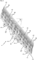
- the weed harrow 1 is intended to be coupled by its front face to an agricultural vehicle, conventionally a tractor, not shown in the figures, the latter having several sources of hydraulic power, an electrical power supply, preferably in 12 Volts, and a GPS geolocation system with a standardized ISOBUS connection.
- the ISOBUS standard (ISO 11783) makes it possible to make communication between an agricultural vehicle and its attached implement compatible, even if they are not from the same manufacturer. It also allows the exchange of data between the agricultural vehicle and plot management software.
- the chassis 2 comprises a main beam 7 extending perpendicularly and on either side of the sagittal plane P of said chassis 2 and being advantageously composed of at least three sections, namely a middle section 71 and two end sections 72 pivotally mounted each on one of the longitudinal ends of said median section 71 around a horizontal axis parallel to said sagittal plane P so as to be able to fold said chassis 2, and therefore the weed harrow 1 according to the invention, to carry out movements on public roads.
- the folding of the chassis 2 is carried out using lifting actuators 8, advantageously double-acting hydraulic cylinders connected to the hydraulic circuit of the agricultural vehicle.
- the main beam 7 may be composed of more than three sections and include, for example, an additional section pivotally mounted on the free end of each of the end sections 72 around a horizontal axis parallel to said sagittal plane P.
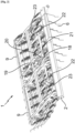
- Said chassis 2 also comprises a plurality of generally horizontal structures 9, each fixed on one of the middle sections 71 and ends 72 of the main beam 7, and supporting at least one basket 5.
- the chassis 2 comprises five structures 9 each supporting two baskets 5.
- the number of structures 9 and baskets 5 can vary depending on the needs of the user.
- the bars 11 of a basket 5 are connected together by a rod 12 so that the pivoting of the bar 11 located at the front of the chassis 2, hereinafter designated by front bar 11', causes a pivoting identical to all the other bars 11 of said basket 5.
- Each of the claw teeth 6 is pivotally mounted on the bar 11 associated around an axis parallel to the longitudinal axis of the latter between a working position, that is to say a position in which each claw tooth 6 is inclined from top to bottom and from the front towards the rear of the chassis 2, and a retracted position, that is to say a position in which each claw tooth 6 extends horizontally and in the direction of the rear of chassis 2, and vice versa.
- said pivot axis is arranged below the bar 11 and each claw tooth 6 extends beyond said bar 11, so that its upper portion located above said upper pivot axis comes to bear against the front face of said bar 11 so as not to allow its lower end to pivot towards the front of the chassis 2 beyond its working position.
- each claw tooth 6 is in the overall shape of an L rotated by 180° and comprises a first wing 61, one of the ends of which is in contact with the ground and a second wing 62 coming perpendicularly from the other end of said first wing 61.
- each of the clawing teeth 6 is pivotally mounted, near the junction between its first and second wings 61, 62, and the second wings 62 of each clawing tooth 6 then extends au- above the bar 11 and towards the rear of the chassis 2.
- each clawing tooth 6 is associated with a traction spring 13 tending to return it to its working position, that is to say to bring the upper portion of the clawing tooth 6 to rest against the associated bar 11 .
- each tension spring 13 is tensioned between a pulling point 14 located at the upper end of said claw tooth 6, where appropriate at the free end of the second wing 62, and a movable grid 15 so that the movement of the latter modifies the tension of said traction spring 13 and, consequently, the pressure exerted on the ground by said clawing tooth 6.
- said grid 15 is integral with each of the two longitudinal members 10 of the associated basket 5 via a front link 16, called a push link, and a rear link 17, said front and rear links 16, 17 being pivotally mounted on the grid 15 and the longitudinal members 10 around axes perpendicular to the sagittal plane P of said chassis 2, said axes being such that their projections on said plane P determine the vertices of a deformable parallelogram so that the grid 15 moves parallel to itself towards the front or rear of the chassis 2.
- the weed harrow 1 comprises an actuator 18, hereinafter called pressure adjustment actuator 18, advantageously a double-acting hydraulic cylinder connected to the hydraulic circuit of the agricultural vehicle, making it possible to modify the tension of the traction spring 13, said pressure adjustment actuator 18 being associated with the grid 15 and disposed between the lower end of the front link 16 and the associated spar 10.
- pressure adjustment actuator 18 advantageously a double-acting hydraulic cylinder connected to the hydraulic circuit of the agricultural vehicle, making it possible to modify the tension of the traction spring 13, said pressure adjustment actuator 18 being associated with the grid 15 and disposed between the lower end of the front link 16 and the associated spar 10.
- the pressure adjustment actuator 18 advantageously makes it possible to adjust the pressure exerted on the ground by the gripping teeth 6 of the two adjacent baskets 5 supported by the same structure 9 of the chassis 2, said pressure adjustment actuator 18 being arranged between the grids 11 of said two baskets 5.
- the weed harrow 1 also makes it possible to adjust the aggressiveness of the claw teeth 6, that is to say the inclination relative to the vertical of the working position of the latter.
- the aggressiveness of the claw teeth 6 that is to say the inclination relative to the vertical of the working position of the latter.
- the weed harrow 1 comprises an actuator 19, hereinafter called aggressiveness adjustment actuator 19, advantageously a double-acting hydraulic cylinder connected to the hydraulic circuit of the agricultural vehicle, arranged substantially horizontally between a structure 9 of the chassis 2 and the upper end of an arm 20 pivotally mounted at its lower end on said structure 9 of the chassis 2 around an axis B perpendicular to the sagittal plane P of said chassis 2.
- Said arm 20 receives between its lower and upper ends a rod 21 s extending perpendicularly to said sagittal plane P and on either side of said arm 20.
- the rod 21 is connected to the front bar 11 of at least one basket 5 associated by a set 22 of rods/lever so that the movement of said rod 21 causes the pivoting of said bar 11.
- the rod 21 advantageously comprises a set 22 of links/lever at each of its ends, each of its sets 22 then being connected to the front bar 11' associated with one of two baskets 5 adjacent supported by the same structure 9 of the chassis 2.
- the aggressiveness adjustment actuator 19 advantageously allows, thanks in particular to the configuration of the rod 21, to adjust the pressure exerted on the ground by the claw teeth 6 of the two adjacent baskets 5 supported by the same structure 9 of the chassis 2.
- the aggressiveness adjustment actuators 19 of the weed harrow 1 being advantageously mounted on the outlets of a volumetric flow divider, the latter receive the same volume of oil and consequently, always have identical lengths between them. The adjustment of the aggressiveness is then uniform over all of the claw teeth 6 of said weed harrow 1.
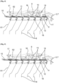
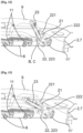
- the weed harrow 1 also makes it possible to retract all the claw teeth 6 of the same basket 5, that is to say to raise the latter relative to the vertical so that they are extend horizontally, their lower ends towards the rear of chassis 2 (Cf. Figure 9 ).
- the retracting position notably avoids passing the claw teeth 6 over crop plots that have already been weeded.
- the weed harrow 1 comprises an actuator 23, hereinafter called retraction actuator 23, advantageously a double-acting hydraulic cylinder connected to the hydraulic circuit of the agricultural vehicle, cooperating with a set 22 of links/lever previously described for move the claw teeth 6 of a basket 5 from their working position in which said claw teeth 6 are at a determined inclination (Cf. figure 8 ), to their retracted position in which said clawing teeth 6 extend horizontally (Cf. Figure 9 ), and reciprocally.
- said retraction actuator 23 is advantageously arranged between the upper end of the lever 221 of the assembly 22 of links/lever associated with the basket 5 and the first link 222 of said assembly 22, that is to say between the upper and lower ends of the latter.
- retraction actuator 23 and the assembly 22 of links/lever are dimensioned to move the claw teeth 6 of a basket 5 from their working position to their retraction position, and vice versa. .
- the weed harrow 1 according to the invention is also particularly interesting because a user can modify one of these different settings without impacting the other settings, which guarantees the durability of the settings.
- each claw tooth 6 is such that its pulling point 14 of the traction spring 13 is positioned on the pivot axis A of the associated bar 11. It is clearly understood that with this specific configuration, whatever the adjustment of the aggressiveness or the position (working or retracting) of the claw teeth 6, the tension springs do not undergo any modification of tension during pivoting of the bars 11.
- the weed harrow 1 combines the mechanical design previously described allowing the retraction of all or part of the claw teeth 6 without impact on the predefined settings of ground pressure and aggressiveness, when using GPS mapping.
- the chassis 2 of the weed harrow 1 according to the invention is equipped, in a conventional manner, with a plurality of members, partially represented in the figures, making it possible to regulate the flow rate supplied continuously by a hydraulic unit of the vehicle agricultural and filtering oil.
- the computer unit 24 is advantageously configured in the factory to respond to all possible configurations, each configuration depending in particular on the number of baskets 5 and retraction actuators 23.
- the information from the geolocation system of the agricultural vehicle indicating the areas of the land to be harrowed is transmitted from the agricultural vehicle to the computer unit 24 in order to detect or not all or part of the claw teeth 6 at locations determined using the associated retraction actuators 23.
- this configuration of the weed harrow 1 allows efficient and precise weeding of each square meter of the field to be weeded.
- the implementation of said weed harrow 1 is quick and easy in particular due, on the one hand, to an independent adjustment of the pressure exerted on the ground, the aggressiveness and the position of the teeth 6 of clawing of each baskets 5 and, on the other hand, the possibility of retracting all or part of the clawing teeth 6 of one or more baskets 5 without impact on the predefined settings of the ground pressure and the aggressiveness of teeth 6 scratching other baskets 5.
- weed harrow 1 is, of course, used for mechanical weeding work in a field.
Landscapes
- Life Sciences & Earth Sciences (AREA)
- Engineering & Computer Science (AREA)
- Mechanical Engineering (AREA)
- Soil Sciences (AREA)
- Environmental Sciences (AREA)
- Zoology (AREA)
- Soil Working Implements (AREA)
Applications Claiming Priority (1)
| Application Number | Priority Date | Filing Date | Title |
|---|---|---|---|
| FR2208783A FR3139265B1 (fr) | 2022-09-01 | 2022-09-01 | Herse etrille |
Publications (3)
| Publication Number | Publication Date |
|---|---|
| EP4331331A1 true EP4331331A1 (de) | 2024-03-06 |
| EP4331331B1 EP4331331B1 (de) | 2024-10-09 |
| EP4331331C0 EP4331331C0 (de) | 2024-10-09 |
Family
ID=83899597
Family Applications (1)
| Application Number | Title | Priority Date | Filing Date |
|---|---|---|---|
| EP23194012.3A Active EP4331331B1 (de) | 2022-09-01 | 2023-08-29 | Hackstriegel |
Country Status (4)
| Country | Link |
|---|---|
| EP (1) | EP4331331B1 (de) |
| ES (1) | ES2994254T3 (de) |
| FR (1) | FR3139265B1 (de) |
| PL (1) | PL4331331T3 (de) |
Cited By (1)
| Publication number | Priority date | Publication date | Assignee | Title |
|---|---|---|---|---|
| CN119234492A (zh) * | 2024-11-18 | 2025-01-03 | 江苏锐森卓科新材料科技有限公司 | 一种蔬菜种植用松土除草设备 |
Citations (5)
| Publication number | Priority date | Publication date | Assignee | Title |
|---|---|---|---|---|
| EP3167698A1 (de) * | 2015-10-23 | 2017-05-17 | Deere & Company | System zur rückstandsdetektion und gerätesteuerung und verfahren dafür |
| WO2018191767A1 (de) * | 2017-04-18 | 2018-10-25 | Schoels Juergen | Bodenbearbeitungsgerät |
| RU195217U1 (ru) * | 2019-05-22 | 2020-01-17 | Акционерное общество "Алтайский завод сельскохозяйственного машиностроения" | Борона зубовая |
| EP3903549A1 (de) | 2020-04-27 | 2021-11-03 | Horsch Maschinen GmbH | Bodenbearbeitungsmaschine, vorzugsweise landwirtschaftlicher hackstriegel und verfahren zum einstellen einer vorspannkraft an einem hackstriegel |
| EP3977851A1 (de) | 2020-10-02 | 2022-04-06 | Fliegl Agro-Center GmbH | Striegelvorrichtung zur bodenbearbeitung mit synchron verstellbaren striegelzinken |
-
2022
- 2022-09-01 FR FR2208783A patent/FR3139265B1/fr active Active
-
2023
- 2023-08-29 EP EP23194012.3A patent/EP4331331B1/de active Active
- 2023-08-29 ES ES23194012T patent/ES2994254T3/es active Active
- 2023-08-29 PL PL23194012.3T patent/PL4331331T3/pl unknown
Patent Citations (5)
| Publication number | Priority date | Publication date | Assignee | Title |
|---|---|---|---|---|
| EP3167698A1 (de) * | 2015-10-23 | 2017-05-17 | Deere & Company | System zur rückstandsdetektion und gerätesteuerung und verfahren dafür |
| WO2018191767A1 (de) * | 2017-04-18 | 2018-10-25 | Schoels Juergen | Bodenbearbeitungsgerät |
| RU195217U1 (ru) * | 2019-05-22 | 2020-01-17 | Акционерное общество "Алтайский завод сельскохозяйственного машиностроения" | Борона зубовая |
| EP3903549A1 (de) | 2020-04-27 | 2021-11-03 | Horsch Maschinen GmbH | Bodenbearbeitungsmaschine, vorzugsweise landwirtschaftlicher hackstriegel und verfahren zum einstellen einer vorspannkraft an einem hackstriegel |
| EP3977851A1 (de) | 2020-10-02 | 2022-04-06 | Fliegl Agro-Center GmbH | Striegelvorrichtung zur bodenbearbeitung mit synchron verstellbaren striegelzinken |
Cited By (1)
| Publication number | Priority date | Publication date | Assignee | Title |
|---|---|---|---|---|
| CN119234492A (zh) * | 2024-11-18 | 2025-01-03 | 江苏锐森卓科新材料科技有限公司 | 一种蔬菜种植用松土除草设备 |
Also Published As
| Publication number | Publication date |
|---|---|
| EP4331331B1 (de) | 2024-10-09 |
| FR3139265A1 (fr) | 2024-03-08 |
| FR3139265B1 (fr) | 2024-09-20 |
| EP4331331C0 (de) | 2024-10-09 |
| ES2994254T3 (en) | 2025-01-21 |
| PL4331331T3 (pl) | 2025-03-24 |
Similar Documents
| Publication | Publication Date | Title |
|---|---|---|
| EP1345487B1 (de) | Präzisionsschälpflug mit eingebauten sähelementen | |
| EP3834592B1 (de) | Pflug mit mindestens einer zusätzlichen bodenbearbeitungseinrichtung | |
| EP4331331B1 (de) | Hackstriegel | |
| FR2944410A1 (fr) | Dispositif agricole de travail du sol | |
| EP2457426A1 (de) | Sämaschine mit versetzten Stutzelementen | |
| EP4241545B1 (de) | Universal-biredder | |
| EP2361491B1 (de) | Sämaschine mit Einstellvorrichtungen mit verringertem Raumbedarf | |
| EP3698612A1 (de) | Pflug mit kompensationsvorrichtung der seitlichen belastung beim arbeiten | |
| WO1997024025A1 (fr) | Dispositif d'ameublissement du sol | |
| FR2835691A1 (fr) | Semoir | |
| EP4460172B1 (de) | Vorrichtung und system zur schnittstelle zwischen einer landwirtschaftlichen traktorkupplung und einem arbeitsgerät | |
| EP1959722B1 (de) | Bestellkombination | |
| EP1466516B1 (de) | Landwirtschaftliche Maschine mit zumindest einem Rad | |
| WO2005077137A2 (fr) | Systeme de charrue a socs | |
| EP2880969B1 (de) | Bodenauflockerungsvorrichtung, die zum Ziehen bestimmt ist und ein verformbares Parallelogramm umfasst, das mit mindestens einem Auflockerungselement ausgestattet ist | |
| WO1997015177A1 (fr) | Charrue reversible portee a largeur variable avec dispositif de recentrage du bati sur l'axe de retournement | |
| FR2894766A1 (fr) | Charrue reversible portee equipee d'une roue de transport laterale | |
| EP0872167A1 (de) | Pflugkörperregelungs- und -Verschiebungsvorrichtung | |
| FR2619667A1 (fr) | Perfectionnement aux outils agricoles de reprise de labour | |
| FR2590109A1 (fr) | Chassis porteur d'outils pour l'agriculture | |
| FR2695535A1 (fr) | Dispositif d'enfouissement de produits liquides, tel que du lisier. | |
| EP2076110B1 (de) | Kreiselegge mit schar | |
| EP4706357A1 (de) | Schleppvorrichtung mit einem verformbaren parallelogramm, das mindestens ein hackelement trägt | |
| FR3130499A1 (fr) | Appareil agricole comprenant des peignes de travail du sol et un dispositif de commande de l’inclinaison des peignes | |
| FR3012721A1 (de) |
Legal Events
| Date | Code | Title | Description |
|---|---|---|---|
| PUAI | Public reference made under article 153(3) epc to a published international application that has entered the european phase |
Free format text: ORIGINAL CODE: 0009012 |
|
| STAA | Information on the status of an ep patent application or granted ep patent |
Free format text: STATUS: THE APPLICATION HAS BEEN PUBLISHED |
|
| AK | Designated contracting states |
Kind code of ref document: A1 Designated state(s): AL AT BE BG CH CY CZ DE DK EE ES FI FR GB GR HR HU IE IS IT LI LT LU LV MC ME MK MT NL NO PL PT RO RS SE SI SK SM TR |
|
| RAP3 | Party data changed (applicant data changed or rights of an application transferred) |
Owner name: KVERNELAND GROUP LES LANDES-GENUSSON |
|
| STAA | Information on the status of an ep patent application or granted ep patent |
Free format text: STATUS: REQUEST FOR EXAMINATION WAS MADE |
|
| 17P | Request for examination filed |
Effective date: 20240604 |
|
| GRAP | Despatch of communication of intention to grant a patent |
Free format text: ORIGINAL CODE: EPIDOSNIGR1 |
|
| STAA | Information on the status of an ep patent application or granted ep patent |
Free format text: STATUS: GRANT OF PATENT IS INTENDED |
|
| GRAS | Grant fee paid |
Free format text: ORIGINAL CODE: EPIDOSNIGR3 |
|
| INTG | Intention to grant announced |
Effective date: 20240801 |
|
| GRAA | (expected) grant |
Free format text: ORIGINAL CODE: 0009210 |
|
| STAA | Information on the status of an ep patent application or granted ep patent |
Free format text: STATUS: THE PATENT HAS BEEN GRANTED |
|
| AK | Designated contracting states |
Kind code of ref document: B1 Designated state(s): AL AT BE BG CH CY CZ DE DK EE ES FI FR GB GR HR HU IE IS IT LI LT LU LV MC ME MK MT NL NO PL PT RO RS SE SI SK SM TR |
|
| REG | Reference to a national code |
Ref country code: CH Ref legal event code: EP |
|
| REG | Reference to a national code |
Ref country code: DE Ref legal event code: R096 Ref document number: 602023000703 Country of ref document: DE |
|
| REG | Reference to a national code |
Ref country code: IE Ref legal event code: FG4D Free format text: LANGUAGE OF EP DOCUMENT: FRENCH |
|
| U01 | Request for unitary effect filed |
Effective date: 20241029 |
|
| U07 | Unitary effect registered |
Designated state(s): AT BE BG DE DK EE FI FR IT LT LU LV MT NL PT RO SE SI Effective date: 20241108 |
|
| REG | Reference to a national code |
Ref country code: ES Ref legal event code: FG2A Ref document number: 2994254 Country of ref document: ES Kind code of ref document: T3 Effective date: 20250121 |
|
| PG25 | Lapsed in a contracting state [announced via postgrant information from national office to epo] |
Ref country code: IS Free format text: LAPSE BECAUSE OF FAILURE TO SUBMIT A TRANSLATION OF THE DESCRIPTION OR TO PAY THE FEE WITHIN THE PRESCRIBED TIME-LIMIT Effective date: 20250209 Ref country code: HR Free format text: LAPSE BECAUSE OF FAILURE TO SUBMIT A TRANSLATION OF THE DESCRIPTION OR TO PAY THE FEE WITHIN THE PRESCRIBED TIME-LIMIT Effective date: 20241009 |
|
| PG25 | Lapsed in a contracting state [announced via postgrant information from national office to epo] |
Ref country code: NO Free format text: LAPSE BECAUSE OF FAILURE TO SUBMIT A TRANSLATION OF THE DESCRIPTION OR TO PAY THE FEE WITHIN THE PRESCRIBED TIME-LIMIT Effective date: 20250109 |
|
| PG25 | Lapsed in a contracting state [announced via postgrant information from national office to epo] |
Ref country code: GR Free format text: LAPSE BECAUSE OF FAILURE TO SUBMIT A TRANSLATION OF THE DESCRIPTION OR TO PAY THE FEE WITHIN THE PRESCRIBED TIME-LIMIT Effective date: 20250110 |
|
| PG25 | Lapsed in a contracting state [announced via postgrant information from national office to epo] |
Ref country code: RS Free format text: LAPSE BECAUSE OF FAILURE TO SUBMIT A TRANSLATION OF THE DESCRIPTION OR TO PAY THE FEE WITHIN THE PRESCRIBED TIME-LIMIT Effective date: 20250109 |
|
| PG25 | Lapsed in a contracting state [announced via postgrant information from national office to epo] |
Ref country code: SM Free format text: LAPSE BECAUSE OF FAILURE TO SUBMIT A TRANSLATION OF THE DESCRIPTION OR TO PAY THE FEE WITHIN THE PRESCRIBED TIME-LIMIT Effective date: 20241009 |
|
| PG25 | Lapsed in a contracting state [announced via postgrant information from national office to epo] |
Ref country code: SK Free format text: LAPSE BECAUSE OF FAILURE TO SUBMIT A TRANSLATION OF THE DESCRIPTION OR TO PAY THE FEE WITHIN THE PRESCRIBED TIME-LIMIT Effective date: 20241009 |
|
| PLBE | No opposition filed within time limit |
Free format text: ORIGINAL CODE: 0009261 |
|
| STAA | Information on the status of an ep patent application or granted ep patent |
Free format text: STATUS: NO OPPOSITION FILED WITHIN TIME LIMIT |
|
| 26N | No opposition filed |
Effective date: 20250710 |
|
| U20 | Renewal fee for the european patent with unitary effect paid |
Year of fee payment: 3 Effective date: 20250827 |
|
| PGFP | Annual fee paid to national office [announced via postgrant information from national office to epo] |
Ref country code: ES Payment date: 20250926 Year of fee payment: 3 |
|
| PGFP | Annual fee paid to national office [announced via postgrant information from national office to epo] |
Ref country code: PL Payment date: 20250821 Year of fee payment: 3 |
|
| PGFP | Annual fee paid to national office [announced via postgrant information from national office to epo] |
Ref country code: CZ Payment date: 20250827 Year of fee payment: 3 |
|
| PG25 | Lapsed in a contracting state [announced via postgrant information from national office to epo] |
Ref country code: MC Free format text: LAPSE BECAUSE OF FAILURE TO SUBMIT A TRANSLATION OF THE DESCRIPTION OR TO PAY THE FEE WITHIN THE PRESCRIBED TIME-LIMIT Effective date: 20241009 |