EP4331337A1 - Épandeur centrifuge et procédé de fonctionnement d'un épandeur centrifuge - Google Patents
Épandeur centrifuge et procédé de fonctionnement d'un épandeur centrifuge Download PDFInfo
- Publication number
- EP4331337A1 EP4331337A1 EP23187760.6A EP23187760A EP4331337A1 EP 4331337 A1 EP4331337 A1 EP 4331337A1 EP 23187760 A EP23187760 A EP 23187760A EP 4331337 A1 EP4331337 A1 EP 4331337A1
- Authority
- EP
- European Patent Office
- Prior art keywords
- spreading
- grit
- centrifugal spreader
- disk
- control device
- Prior art date
- Legal status (The legal status is an assumption and is not a legal conclusion. Google has not performed a legal analysis and makes no representation as to the accuracy of the status listed.)
- Pending
Links
Images




Classifications
-
- A—HUMAN NECESSITIES
- A01—AGRICULTURE; FORESTRY; ANIMAL HUSBANDRY; HUNTING; TRAPPING; FISHING
- A01C—PLANTING; SOWING; FERTILISING
- A01C17/00—Fertilisers or seeders with centrifugal wheels
- A01C17/001—Centrifugal throwing devices with a vertical axis
-
- A—HUMAN NECESSITIES
- A01—AGRICULTURE; FORESTRY; ANIMAL HUSBANDRY; HUNTING; TRAPPING; FISHING
- A01C—PLANTING; SOWING; FERTILISING
- A01C17/00—Fertilisers or seeders with centrifugal wheels
- A01C17/006—Regulating or dosing devices
Definitions
- the invention relates to a centrifugal spreader for spreading grit.
- the invention also relates to a method for operating a centrifugal spreader.
- gritting materials In agriculture, large quantities of spreading materials such as mineral fertilizers are sometimes spread to ensure productive growth of crops and at the same time improve harvest quality.
- optimal distribution of the gritting materials is important not only with regard to the costs associated with the gritting materials, but also with regard to environmental damage caused by incorrect or excessive use of these gritting materials.
- Centrifugal spreaders are used, among other things, to distribute the grit. With these centrifugal spreaders, a metered mass flow is fed to one (usually two) rotating spreading discs (e.g. also called centrifugal discs, spreading plates or the like), which is then fed through the rotation of the spreading disc with spreading blades attached to it, creating a spreading pattern over the entire surface of an agricultural area Usable area is distributed, i.e. is spread.
- rotating spreading discs e.g. also called centrifugal discs, spreading plates or the like
- An ideal application of the grit also requires an exact determination of the amount of grit spread per unit area, in particular an exact determination of the mass flow of grit per unit area applied by the centrifugal spreader.
- this mass flow is determined based on a changing torque of the spreading disc, a representative torque of at least one shaft in a drive train (e.g. drive motor, motor shaft or the like) of the spreading disc being determined using sensors and then using this Torque, the mass flow associated with this torque is determined using a mass flow-torque characteristic.
- a drive train e.g. drive motor, motor shaft or the like
- the object of the invention is therefore to eliminate the described disadvantages of the prior art, in particular to create a centrifugal spreader with which flexible adjustment to a wide variety of spreading materials is possible.
- a centrifugal spreader also called fertilizer spreader
- the grit can expediently be granular material in the form of a mineral fertilizer.
- the centrifugal spreader comprises at least one frame structure, with at least one storage container for storing the grit to be spread.
- the storage container can, for example, be part of the frame construction, alternatively the storage container can also be attached to the frame construction.
- the storage container expediently comprises in particular a chamber for storing the grit to be distributed, but alternatively or additionally the storage container could also have two or more, in particular separate chambers, in order to be able to store two or more different grit, for example.
- the centrifugal spreader also comprises at least two spreading discs, each of which is assigned a metering device, the metering devices each being set up to feed stored grit from the storage container through an outlet opening in adjustable quantities to a respective spreading disc, generating a respective material flow.
- the centrifugal spreader comprises at least two drive devices that can be controlled and/or regulated by means of a control device, each of which is technically coupled to a spreading disc (e.g. coupled in terms of drive technology) and is set up to drive the respective spreading disc at a variable speed.
- a control device e.g. coupled in terms of drive technology
- the centrifugal spreader can also comprise at least one sensor device which is signal-connected and/or signal-connectable to the control device and which is set up to detect a respective load moment caused by the mass flow on the respective spreading disc.
- the centrifugal spreader can also comprise at least one sensor device which is signal-connected and/or signal-connectable to the control device and which is set up to detect a respective load moment caused by the mass flow on the respective spreading disc.
- two or more sensors forming the sensor device can be provided depending on the number of diffusing disks.
- the lens lenses are each mounted on the frame structure by means of a mounting device. It is particularly possible for the sensor device to be operatively coupled to one of the mounting devices.
- An active coupling in particular includes mounting the sensor device on the mounting device.
- the diffusing disks prefferably be mounted on the frame structure by means of a mounting device in such a way that the position of the respective diffusing disk relative to the outlet opening can be changed by the mounting device, preferably in such a way that a feed point of the respective material flow on the respective diffusing disk can be changed.
- a much more flexible, adjustable centrifugal spreader is created.
- a point of application of the spreading material onto the spreading disk can be influenced in such a way that a respective spreading pattern can be adjusted even more precisely and thus the distribution of the spreading material can be carried out much more precisely.
- At least two spreading blades to be attached to each of these, which take the spreading material with them when the spreading disk rotates and in accordance with that generated by the drive devices Speed of the spreading disc, accelerate accordingly and generate a Throwing speed away, which creates the corresponding scatter pattern.
- the position of the feed point relative to the spreading disc and the corresponding spreading blades is important, as the throwing speed of the spreading material can be influenced and, in turn, the spreading pattern and in particular the working width can be influenced based on the throwing speed of the spreading material.
- the position of the spreading blades on the spreading disks prefferably adjustable.
- the spreading discs In order to achieve a centrifugal spreader, by means of which an even more flexible adaptation to a wide variety of spreading materials is achieved, in particular by means of which an adaptation of the working width to a wide variety of spreading materials is achieved, it is possible according to a further development of the invention for the spreading discs to be mounted in this way on the frame structure by means of the mounting device are that changing the position of the respective lens by means of the mounting device causes a change in the respective feed point relative to the respective outlet opening in two directions, in particular a change in the X direction and Y direction of a coordinate system, the origin of which is the center of the outlet opening .
- the position can be changed in two directions independently of one another or can be forcibly guided in two directions.
- the position of the respective diffusers to be changed by means of the mounting device not to occur concentrically with respect to the outlet opening.
- a simple structure of the centrifugal spreader can be achieved according to an embodiment variant in that the mounting devices are mounted on the frame structure so that they can pivot about upright axes, with a position of the respective spreading disc relative to the respective outlet opening being rotatably changeable. It should be noted that a center point of the lens and the upright axis are each spaced apart from one another.
- a pivot angle of the mounting devices relative to the frame structure is at least 135° or at least 90° or at least 45°.
- the pivoting angle in particular includes a pivoting range of the mounting device between its respective end positions, ie a pivoting angle, or a pivoting range of the mounting device relative to the frame structure is therefore at least 135° or at least 90° or at least 45°.
- a swivel angle can in turn be predetermined by the size of the respective lens.
- the pivot angle has such a size that, in a plan view, the outlet opening is completely exposed compared to the lens, which can, for example, simplify the emptying of residual quantities of the storage container.
- the mounting devices are mounted on the frame structure so as to be displaceable relative to the frame structure, with the spreading discs being displaced transversely to the direction of travel and/or in the direction of travel or opposite to the direction of travel and/or in a pivoting angle between 0 ° and 90° or at a swivel angle between 25° and 75° relative to the direction of travel.
- the position of the respective lens it is therefore possible for the position of the respective lens to be changed axially and/or translationally.
- a further development of the invention can provide that the diffusers are mounted on the frame structure by means of the mounting device in such a way that the position of the respective diffuser is changed by means of the respective mounting device while maintaining an at least essentially constant height distance between the diffuser and the outlet opening and/or takes place under a changing height distance between the lens and the outlet opening, whereby the difference in the maximum height distances is a maximum of 25cm or a maximum of 15cm. It can also apply here that the position of the lens relative to the outlet opening is changed taking the height distance into account.
- the lens lenses it is expediently preferably conceivable for the lens lenses to be mounted on the frame structure by means of the mounting device in such a way that the position of the respective lens lens is changed by means of the respective mounting device in mutually opposite directions (e.g. left and right to the direction of travel) and/or in mutually running directions (e.g. towards the respective center of the centrifugal spreader) and/or in intersecting directions (e.g. left and right to the direction of travel and in the direction of the respective center of the centrifugal spreader).
- mutually opposite directions e.g. left and right to the direction of travel
- mutually running directions e.g. towards the respective center of the centrifugal spreader
- intersecting directions e.g. left and right to the direction of travel and in the direction of the respective center of the centrifugal spreader
- the centrifugal spreader can preferably provide that the assembly devices are mounted by means of a sliding guide (e.g. linear guide, linear drive and/or Like.) and/or a parallelogram bearing and/or a pivot bearing are mounted on the frame structure.
- a sliding guide e.g. linear guide, linear drive and/or Like.
- a parallelogram bearing and/or a pivot bearing are mounted on the frame structure.
- the respective positions of the scattering disks relative to the respective outlet openings can be adjustable in a variety of ways, for example it is possible for the position of the respective scattering disk to be changed relative to the respective outlet opening by means of the respective mounting device within adjustable or predetermined end position positions and/or takes place in a fixed position grid and/or takes place continuously.
- each mounting device is operatively coupled to an adjustment device that is signal-connected and/or signal-connectable to the control device in order to change the position of the lens lenses by means of the respective mounting device, the adjustment device being formed in particular by at least one linear drive and/or a pivoting drive is, and wherein the adjusting device is in particular designed to be remotely controllable.
- remote control can include, for example, operation from an operator's stand (e.g. tractor) and, for example, by means of an operating unit (e.g. terminal, control device, or the like).
- the metering devices can in particular be designed in such a way that they are each designed as outlet openings whose size can be adjusted by means of at least one slide, the slides of the respective metering devices being adjustable independently of one another.
- the metering devices could also be designed as a rotary valve or the like.
- the metering devices are designed in such a way that a variable amount of grit can flow or be conveyed from the storage container in the direction of the spreading disc.
- the metering device is designed in such a way that a relative position of the outlet opening relative to the storage container is adjustable.
- the position of the outlet opening relative to the storage container can be adjustable in addition to the spreading disks and thus a position of the delivery point can be set even more precisely.
- a fertilizer guide element e.g. chute, funnel or the like
- the side of which facing the spreading disk is positioned in the X direction via a lever mechanism and Y direction of a coordinate system, the origin of which is the center of the outlet opening, is changeable and/or the side facing the lens has a changeable opening cross-section, in particular one in its size and/or in its contour (e.g. round, oval or the like.) has a variable opening cross section.
- the delivery point can be set even more precisely.
- such a fertilizer guide element can also be used to change the respective shape and characteristics of the application point on the spreading disc and adapt it to, for example, special spreading materials.
- a preferred embodiment variant of the centrifugal spreader can provide that the drive devices are each formed by at least one hydraulic motor or electric motor, which is each mounted on the mounting device.
- a mechanical drive for example using a cardan shaft drive, would also be conceivable.
- the respective drive devices can be adjustable independently of one another, i.e. that the speeds of the scattering disks can be adjusted independently of one another.
- the sensor device To determine the amount of grit dosed by means of the dosing device, i.e. to determine the amount of grit applied per unit area, it is possible according to a further development of the invention for the sensor device to be set up to detect a respective amount of material caused by the flow of material on the respective scattering disc Load moment to detect a force acting on the assembly device. It is possible for a corresponding load moment to be calculated based on the detected force using the control device and/or the sensor device. Alternatively or additionally, a mass flow of the grit can be calculated using the sensor device and/or the control device based on the load moment.
- the detection of the force acting on the mounting device includes at least one force acting on the mounting of the mounting device on the frame structure (e.g. a force on the upright axle) and/or a force acting on a connecting device of the mounting device with the adjusting device Mounting device comprises force acting and / or comprises a force acting on the adjusting device.
- a force can also be detected on other parts of the assembly device that are suitable for this purpose.
- the centrifugal spreader comprises, according to a further development, a measuring device which is signal-connected and/or signal-connectable to the control device and which is set up to determine a position (e.g. distance in the X direction and/or Y direction and/or height distance). to detect the respective diffuser disc relative to the respective outlet opening indirectly and/or directly, the control device being set up to calculate the load moment from this, taking the detected position into account.
- a position e.g. distance in the X direction and/or Y direction and/or height distance
- the centrifugal spreader can be designed to be able to equip it with spreading discs with different diameters in order to be able to achieve a wide variety of working widths, for example, in which case it is conceivable that diameters of the spreading disc are stored and/or can be stored in the control device and the control device for this purpose is set up to calculate the load moment based on the diameter of the lens. For example, forces detected by the sensor device can change based on the diameter of the lens, and this can be taken into account by the control device.
- centrifugal spreader can provide that the storage container is coupled to a fill level detection device (e.g. weighing device, fill level sensor and / or the like), which is set up to detect a changing fill level of the storage container, the control device being set up to determine the position of the To change the spreading disc and/or the speed of the spreading disc and/or the amount of grit dosed by means of the metering device based on the changing fill level.
- a fill level detection device e.g. weighing device, fill level sensor and / or the like
- the control device being set up to determine the position of the To change the spreading disc and/or the speed of the spreading disc and/or the amount of grit dosed by means of the metering device based on the changing fill level.
- centrifugal spreader can provide that the control device is set up to change the position of the spreading disc and/or the speed of the spreading disc and/or the amount of grit dosed by means of the metering device based on the load torque.
- centrifugal spreader can provide that the control device is set up to change the position of the spreading disc and/or the amount of grit metered using the metering device based on the speed of the spreading discs.
- centrifugal spreader can provide that the control device is set up to process a specification of a working width and, based on the specification of the working width, to change the position of the spreading disc and/or the speed of the spreading disc and/or the amount of grit dosed by means of the metering device.
- centrifugal spreader can provide that the control device is set up to process a quantity of grit per unit area and, based on a specification of the amount of grit per unit area, the position of the spreading disc and/or the speed of the spreading disc and/or the amount of by means of the Dosing device to change the dosed grit.
- centrifugal spreader can provide that a detection device is provided which is set up to directly or indirectly detect a scattering image generated by the scattering discs (e.g. size and/or shape of the scattering image) and that the control device is set up to detect the position of the scattering disc and / or to change the speed of the spreading disc and / or the amount of grit dosed by means of the metering device based on the recorded spreading pattern.
- a detection device is provided which is set up to directly or indirectly detect a scattering image generated by the scattering discs (e.g. size and/or shape of the scattering image) and that the control device is set up to detect the position of the scattering disc and / or to change the speed of the spreading disc and / or the amount of grit dosed by means of the metering device based on the recorded spreading pattern.
- centrifugal spreader can provide that a speed measuring device is provided which is set up to record a speed at which the centrifugal spreader is moved along the arable land and that the control device is set up to determine the position of the spreading disc and/or the speed of the spreading disc and/or or to change the amount of grit dosed by means of the metering device based on the speed, in particular to increase or decrease based on a changing speed (i.e. acceleration, deceleration, constant).
- a speed measuring device is provided which is set up to record a speed at which the centrifugal spreader is moved along the arable land and that the control device is set up to determine the position of the spreading disc and/or the speed of the spreading disc and/or or to change the amount of grit dosed by means of the metering device based on the speed, in particular to increase or decrease based on a changing speed (i.e. acceleration, deceleration, constant).
- the control device has, for example, a computer unit, an on-board computer and/or the like and also includes a control and/or regulation circuit, in particular a hydraulic and/or pneumatic and/or electrical control and/or regulation circuit, wherein the control and/or regulation circuit / or control circuit is expediently designed for hydraulic and / or pneumatic and / or electrical signal and / or command transmission. Which signal and/or command transmission can also take place wirelessly (e.g. via WLAN).
- a control and/or regulation circuit in particular a hydraulic and/or pneumatic and/or electrical control and/or regulation circuit, wherein the control and/or regulation circuit / or control circuit is expediently designed for hydraulic and / or pneumatic and / or electrical signal and / or command transmission.
- Which signal and/or command transmission can also take place wirelessly (e.g. via WLAN).
- control device includes, in particular, the entirety of the components for signal and/or command transmission. Accordingly, computer units, CPUs and/or the like are also included. Control devices integrated into the respective sensors or sensor units or sensor arrangements are also correspondingly included. It should also be noted that the signals and/or data from the sensors/measuring devices/detection devices and/or the like can each be used as feedback for a control and/or regulating variable.
- control and regulations and control device can refer to electronic and/or pneumatic and/or hydraulic controls or regulations which, depending on the training, can take on control tasks and/or regulation tasks. Even if the term “taxes” is used here, it can also usefully include “rules”. Likewise, when the term “rules” is used, “control” can also be included.
- a method for operating a centrifugal spreader is provided.
- the method includes at least a provision of a frame structure, with at least one storage container for storing the grit to be distributed, and a provision of two spreading discs, each of which is assigned a metering device, wherein the metering devices are each set up so that stored grit is discharged from the storage container through an outlet opening in an adjustable manner Quantities are to be fed to a diffusing disk while generating a respective material flow, the diffusing disks each being mounted on the frame structure by means of a mounting device and the position of which can be changed relative to the respective outlet opening.
- the method includes providing two drive devices that can be controlled and/or regulated by means of a control device, each of which is technically coupled to a lens and is set up to drive the respective lens at a variable speed.
- the method includes preferably providing a sensor device which is signal-connected and/or signal-connectable to the control device and which is set up to detect a respective load moment caused by the material flow on the respective lens, wherein the sensor device is each operatively coupled to a mounting device .
- the method includes, in particular, an adjustment of the working width of the centrifugal spreader by changing the respective position of the respective spreading disk relative to the respective outlet opening in such a way that the feed point of the respective material stream on the respective spreading disk is changed.
- the method includes, in particular, changing the respective position of the respective spreading disc relative to the respective outlet opening and/or the speed of the respective spreading disc and/or the amount of grit dosed by means of the dosing device by means of the control device such that the respective load torque reaches a maximum value does not exceed.
- the method can be carried out in particular with a centrifugal spreader according to one of the previous exemplary embodiments.
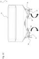
- FIG Figures 1A to 1F out An exemplary embodiment of a centrifugal spreader 10 is shown in FIG Figures 1A to 1F out.
- the centrifugal spreader 10 is used to distribute spreading goods such as fertilizer, seeds and/or the like, which spreading goods are in particular designed as granular spreading goods.
- the centrifugal spreader 10 is in particular set up to carry out a method as described in this document, i.e. to carry out a method according to one of the aforementioned exemplary embodiments.
- the centrifugal spreader 10 includes a frame structure 12 with a hitch 14 in the form of a so-called three-point hitch for coupling the centrifugal spreader 10 to a towing vehicle (not shown here) (e.g. tractor).
- a towing vehicle e.g. tractor
- a storage container 16 is attached to the frame structure 12 for storing the grit to be spread.
- the storage container 16 has a chamber for carrying one type of grit, but could also have two or more chambers for carrying two or more types of grit.
- the storage container 16 tapers downwards in a funnel shape and has two outlet openings 18.
- Two diffusion disks 20 are arranged below the outlet openings 18, each of which is assigned a metering device 22 (see Figure 1D ).
- the metering device 22 can expediently be designed in a manner known per se and, for example, as a slide system with a slide 24 that can be adjusted by means of an actuator 26, that is to say that the metering devices 22, for example, by means of at least one slide 24 in their size adjustable outlet openings 18 can be formed.
- the metering device 22 is expediently set up in particular to supply stored grit from the storage container 16 through the outlet opening 18 in adjustable quantities to a respective scattering disk 20, generating a respective material flow.
- the metering devices 22 can each be adjustable independently of one another.
- the spin control 10 also includes two drive devices 28 that can be controlled and/or regulated by means of a control device, each of which is technically coupled to a diffusing disk 20 and is set up to drive the respective diffusing disk 20 at a variable speed.
- two spreading blades are attached to each of these, which take the spreading material with them when the spreading disk 20 rotates and accelerate and lower it accordingly in accordance with the speed of the spreading disk 20 generated by the drive devices 28 Generating a throwing speed, which creates the corresponding scatter pattern.
- the position of the feed point 32 relative to the spreading disk 20 and the corresponding spreading blades is important, since the throwing speed of the spreading material can be influenced and, in turn, the spreading pattern and in particular the working width can be influenced based on the throwing speed of the spreading material .
- the diffusing disks 20 are each mounted on the frame structure 12 by means of a mounting device 30 in such a way that a position of the respective diffusing disk relative to the outlet opening 18 can be changed by the mounting device 30, preferably in such a way that a drop point 32 (see Figure 1D ) of the respective material flow on the respective lens 20 can be changed, see for example. Figure 1D and 1F .
- a sensor device 34 is also provided, which is signal-connected and/or signal-connectable to a control device and which is set up to detect a respective load moment caused by the respective material flow on the respective lens 20, the sensor device 34 also being coupled to the mounting device 30 is, that is, expediently attached to the mounting device 30, for example.
- the sensor device 34 is expediently set up to detect a force acting on the mounting device 30 in order to detect a respective load moment caused by the material flow on the respective lens 20. According to the Figure 1D The force acting on the mounting device 30 is detected by detecting the force acting on the mounting of the mounting device 30 on the frame structure 12.
- the mounting devices 30 are each mounted on the frame structure 12 so that they can pivot about upright axes 36, whereby a position of the respective lens 20 relative to the respective outlet opening 18 can be changed in rotation.
- the lens 20 is mounted on the frame structure 12 by means of the mounting device in such a way that the position of the respective lens 20 is changed by means of the respective assembly device 30 while maintaining an at least essentially constant height distance between the lens 20 and the outlet opening 18 . It would also be possible for this to take place with a changing height distance between the lens 20 and the outlet opening 18.
- the diffusing disks 20 are mounted on the frame structure 12 by means of the respective mounting device 30 in such a way that the position of the respective diffusing disk 20 is changed in mutually opposite directions by means of the respective mounting device 30. It would also be possible for this to take place in directions that run towards one another and/or in directions that intersect.
- Changing the position of the lens 20 by means of the mounting device 30 is carried out by means of an adjusting device 38 which is signal-connected and/or signal-connectable to the control device and which is correspondingly operatively coupled to the mounting device 30.
- the adjusting device 38 is each provided by a linear drive educated. However, it could also be formed by a swivel drive or the like.
- the adjusting device 38 is also expediently designed to be remotely controllable.
- the position of the respective lens 20 can be changed in a stepless manner relative to the respective outlet opening 18 by means of the respective mounting device 30.
- An adjustment within adjustable or predetermined end position positions and/or in a fixed position grid would also be conceivable.
- the diffuser disks 20 are pivotable by means of the mounting device 30 at a pivot angle ⁇ relative to the outlet opening 18, the pivot angle ⁇ being of such a size that, in a plan view, the outlet opening 18 is completely exposed relative to the diffuser disk 20 , whereby, for example, emptying residual quantities of the storage container 16 can be simplified.
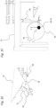
- a single lens 20 is also shown, the position of which can be changed relative to an outlet opening 18 using a mounting device 30 that is slidably mounted on the frame structure 12.
- the displacement takes place by means of two adjustment devices 38 in the form of linear drives which are mounted parallel to one another on the frame structure 12.
- a single lens 20 is also shown, the position of which can be changed relative to an outlet opening 18 using a mounting device 30 which is pivotably mounted on the frame structure 12 by means of a parallelogram.
- the parallelogram is also formed by two adjusting devices 38.
- the parallelogram can be pivoted in the Y direction by means of a further adjusting device 38.
- the diffusing disks 20 can be mounted on the frame structure 12 by means of the mounting device 30 in such a way that changing the position of the respective diffusing disk 20 by means of the mounting device 30 causes the feed point 32 to change relative to the outlet openings 18 in two directions, in particular a change in the X direction and Y direction of a coordinate system whose origin is the center of the outlet opening 18.
- a pivot angle ⁇ of the mounting device 30 relative to the frame structure 12 is at least 135° or at least 90° or at least 45°
Landscapes
- Life Sciences & Earth Sciences (AREA)
- Soil Sciences (AREA)
- Environmental Sciences (AREA)
- Sowing (AREA)
- Fertilizing (AREA)
Applications Claiming Priority (1)
| Application Number | Priority Date | Filing Date | Title |
|---|---|---|---|
| DE102022122451.1A DE102022122451A1 (de) | 2022-09-05 | 2022-09-05 | Schleuderstreuer und Verfahren zum Betreiben eines Schleuderstreuers |
Publications (1)
| Publication Number | Publication Date |
|---|---|
| EP4331337A1 true EP4331337A1 (fr) | 2024-03-06 |
Family
ID=87473820
Family Applications (1)
| Application Number | Title | Priority Date | Filing Date |
|---|---|---|---|
| EP23187760.6A Pending EP4331337A1 (fr) | 2022-09-05 | 2023-07-26 | Épandeur centrifuge et procédé de fonctionnement d'un épandeur centrifuge |
Country Status (2)
| Country | Link |
|---|---|
| EP (1) | EP4331337A1 (fr) |
| DE (1) | DE102022122451A1 (fr) |
Citations (7)
| Publication number | Priority date | Publication date | Assignee | Title |
|---|---|---|---|---|
| EP0410109A1 (fr) * | 1989-07-22 | 1991-01-30 | Rauch Landmaschinenfabrik Gmbh | Epandeur centrifuge pour matériau coulant, en particulier engrais |
| DE4217890A1 (de) * | 1992-05-29 | 1993-12-02 | Amazonen Werke Dreyer H | Schleuderdüngerstreuer |
| EP0963690A1 (fr) | 1998-06-10 | 1999-12-15 | Rauch Landmaschinenfabrik Gmbh | Epandeur centrifuge |
| DE10005230A1 (de) * | 1999-02-25 | 2000-08-31 | Rauch Landmaschfab Gmbh | Zentrifugalstreuer |
| EP0820219B1 (fr) * | 1995-04-08 | 2003-01-02 | Amazonen-Werke H. Dreyer GmbH & Co. KG | Epandeur d'engrais centrifuge |
| DE10238395A1 (de) * | 2001-09-15 | 2003-04-30 | Amazonen Werke Dreyer H | Verteilmaschine |
| EP3406126B1 (fr) * | 2017-05-23 | 2020-02-26 | Amazonen-Werke H. Dreyer GmbH & Co. KG | Épandeur centrifuge à réglage d'épandage amélioré |
Family Cites Families (3)
| Publication number | Priority date | Publication date | Assignee | Title |
|---|---|---|---|---|
| DE19857408A1 (de) * | 1998-12-12 | 2000-06-15 | Bosch Gmbh Robert | Einrichtung zur Dosierung und Verteilung von Streugut |
| DE102007013185A1 (de) * | 2007-03-20 | 2008-09-25 | Lehner Agrar Gmbh | Streuanordnung |
| DE102015004514A1 (de) * | 2015-04-13 | 2016-11-10 | Rauch Landmaschinenfabrik Gmbh | Verfahren zur Regelung des Streugut-Massenstromes von Scheibenstreuern, Scheibenstreuer zur Durchführung eines solchen Verfahrens und Verteilerscheibensatz hierfür |
-
2022
- 2022-09-05 DE DE102022122451.1A patent/DE102022122451A1/de active Pending
-
2023
- 2023-07-26 EP EP23187760.6A patent/EP4331337A1/fr active Pending
Patent Citations (7)
| Publication number | Priority date | Publication date | Assignee | Title |
|---|---|---|---|---|
| EP0410109A1 (fr) * | 1989-07-22 | 1991-01-30 | Rauch Landmaschinenfabrik Gmbh | Epandeur centrifuge pour matériau coulant, en particulier engrais |
| DE4217890A1 (de) * | 1992-05-29 | 1993-12-02 | Amazonen Werke Dreyer H | Schleuderdüngerstreuer |
| EP0820219B1 (fr) * | 1995-04-08 | 2003-01-02 | Amazonen-Werke H. Dreyer GmbH & Co. KG | Epandeur d'engrais centrifuge |
| EP0963690A1 (fr) | 1998-06-10 | 1999-12-15 | Rauch Landmaschinenfabrik Gmbh | Epandeur centrifuge |
| DE10005230A1 (de) * | 1999-02-25 | 2000-08-31 | Rauch Landmaschfab Gmbh | Zentrifugalstreuer |
| DE10238395A1 (de) * | 2001-09-15 | 2003-04-30 | Amazonen Werke Dreyer H | Verteilmaschine |
| EP3406126B1 (fr) * | 2017-05-23 | 2020-02-26 | Amazonen-Werke H. Dreyer GmbH & Co. KG | Épandeur centrifuge à réglage d'épandage amélioré |
Also Published As
| Publication number | Publication date |
|---|---|
| DE102022122451A1 (de) | 2024-03-07 |
Similar Documents
| Publication | Publication Date | Title |
|---|---|---|
| DE3886130T2 (de) | Streuer. | |
| EP0443634A2 (fr) | Distributeur d'engrais centrifuge avec trémie | |
| EP2912934A1 (fr) | Dispositif d'épandage et procédé de détection d'un flux de matière dans un dispositif d'épandage | |
| EP3662735B1 (fr) | Machine de distribution pour épander un matériau d'épandage agricole granulaire et procédé pour distribuer un matériau d'épandage agricole granulaire | |
| EP0540889B2 (fr) | Epandeur d'engrais centrifuge | |
| EP0545894B1 (fr) | Epandeur centrifuge | |
| DE102017120048B4 (de) | Streufahrzeug mit Streutellerneigung | |
| DE4134315A1 (de) | Schleuderduengerstreuer | |
| DE102018131071A1 (de) | Verteilmaschine zum Ausbringen von körnigem landwirtschaftlichem Streugut mit einem verbesserten Fördersystem und Verfahren zum Fördern von körnigem landwirtschaftlichem Streugut | |
| EP4331337A1 (fr) | Épandeur centrifuge et procédé de fonctionnement d'un épandeur centrifuge | |
| DE102022122453A1 (de) | Schleuderstreuer und Verfahren zum Betreiben eines Schleuderstreuers | |
| EP1161856B1 (fr) | Engin de distribution à distributeur centrifuge, notamment épandeur d'engrais | |
| DE10145927A1 (de) | Zentrifugaldüngerstreuer | |
| EP1247437A2 (fr) | Procédé de distribution des matériaux à épandre et engin de distribution à distributeur centrifuge pour mettre ledit procédé en oeuvre | |
| EP3476193A1 (fr) | Appareil d'épandage destiné à l'épandage d'un produit d'épandage | |
| WO2022171639A1 (fr) | Procédé de distribution de matériau particulaire au moyen d'un distributeur agricole | |
| EP4162782A1 (fr) | Unité de rangée pour une machine de distribution agricole et procédé de dépôt de matériau granulaire | |
| EP3195713A1 (fr) | Procédé et épandeur d'engrais | |
| DE102020003359A1 (de) | Verteilmaschine, insbesondere pneumatischer Düngerstreuer | |
| DE102020110367A1 (de) | System für eine landwirtschaftliche Arbeitsmaschine, Verfahren zum Ermitteln einer Position von Arbeitselementen sowie landwirtschaftliche Arbeitsmaschine | |
| EP4550999B1 (fr) | Procédé de commande du fonctionnement régulier d'une unité de soc de semis | |
| EP2907371A1 (fr) | Dispositif d'épandage et procédé de réglage d'une distribution latérale d'un flux de matière répandu par le dispositif d'épandage | |
| DE19902552B4 (de) | Verfahren zum Verteilen von Dünger mittels eines Zweischeibenstreuers | |
| DE102023115653A1 (de) | Behälter für ein landwirtschaftliches gut mit einer fördereinrichtung, landwirtschaftliches arbeitsgerät mit einem behälter und verfahren zum betrieb eines landwirtschaftlichen arbeitsgeräts | |
| EP4260701A1 (fr) | Machine de distribution agricole et procédé d'épandage de produit de distribution agricole |
Legal Events
| Date | Code | Title | Description |
|---|---|---|---|
| PUAI | Public reference made under article 153(3) epc to a published international application that has entered the european phase |
Free format text: ORIGINAL CODE: 0009012 |
|
| STAA | Information on the status of an ep patent application or granted ep patent |
Free format text: STATUS: THE APPLICATION HAS BEEN PUBLISHED |
|
| AK | Designated contracting states |
Kind code of ref document: A1 Designated state(s): AL AT BE BG CH CY CZ DE DK EE ES FI FR GB GR HR HU IE IS IT LI LT LU LV MC ME MK MT NL NO PL PT RO RS SE SI SK SM TR |
|
| STAA | Information on the status of an ep patent application or granted ep patent |
Free format text: STATUS: REQUEST FOR EXAMINATION WAS MADE |
|
| 17P | Request for examination filed |
Effective date: 20240806 |
|
| RBV | Designated contracting states (corrected) |
Designated state(s): AL AT BE BG CH CY CZ DE DK EE ES FI FR GB GR HR HU IE IS IT LI LT LU LV MC ME MK MT NL NO PL PT RO RS SE SI SK SM TR |
|
| GRAP | Despatch of communication of intention to grant a patent |
Free format text: ORIGINAL CODE: EPIDOSNIGR1 |
|
| STAA | Information on the status of an ep patent application or granted ep patent |
Free format text: STATUS: GRANT OF PATENT IS INTENDED |
|
| INTG | Intention to grant announced |
Effective date: 20260219 |
|
| RAP3 | Party data changed (applicant data changed or rights of an application transferred) |
Owner name: HORSCH LEEB APPLICATION SYSTEMS SE & CO. KG |