EP4331344A1 - Procédé de détermination d'un état d'usure d'une moissonneuse agricole automotrice - Google Patents
Procédé de détermination d'un état d'usure d'une moissonneuse agricole automotrice Download PDFInfo
- Publication number
- EP4331344A1 EP4331344A1 EP23179441.3A EP23179441A EP4331344A1 EP 4331344 A1 EP4331344 A1 EP 4331344A1 EP 23179441 A EP23179441 A EP 23179441A EP 4331344 A1 EP4331344 A1 EP 4331344A1
- Authority
- EP
- European Patent Office
- Prior art keywords
- wear
- data
- work
- harvesting machine
- unit
- Prior art date
- Legal status (The legal status is an assumption and is not a legal conclusion. Google has not performed a legal analysis and makes no representation as to the accuracy of the status listed.)
- Granted
Links
Images
Classifications
-
- A—HUMAN NECESSITIES
- A01—AGRICULTURE; FORESTRY; ANIMAL HUSBANDRY; HUNTING; TRAPPING; FISHING
- A01D—HARVESTING; MOWING
- A01D43/00—Mowers combined with apparatus performing additional operations while mowing
- A01D43/08—Mowers combined with apparatus performing additional operations while mowing with means for cutting up the mown crop, e.g. forage harvesters
- A01D43/085—Control or measuring arrangements specially adapted therefor
-
- A—HUMAN NECESSITIES
- A01—AGRICULTURE; FORESTRY; ANIMAL HUSBANDRY; HUNTING; TRAPPING; FISHING
- A01D—HARVESTING; MOWING
- A01D41/00—Combines, i.e. harvesters or mowers combined with threshing devices
- A01D41/12—Details of combines
- A01D41/127—Control or measuring arrangements specially adapted for combines
Definitions
- the present application relates to a method for determining a wear condition of at least one working unit of a self-propelled agricultural harvester, in particular a forage harvester, according to the preamble of independent patent claim 1 and such a self-propelled agricultural harvester, in particular a forage harvester, according to independent patent claim 15.
- a detection arrangement with a magnet arrangement for detecting a state of wear of a chopper of a forage harvester intended for processing a flow of crop is known.
- the wear of working units can not only result from a defect or failure of the working unit or the harvesting machine, but also be or will be relevant for the billing of work orders, the planning of a cultivation and/or harvesting strategy and/or the maintenance of the work units or the harvesting machine. Furthermore, the wear of the working units has a significant influence on the harvesting machine process. Worn working units or worn components of working units mean that the work result of the harvesting machine does not correspond to the target value.
- the present invention relates to a method for determining a wear condition of at least one working unit of a self-propelled agricultural harvester, in particular a forage harvester.
- a sensor device of the harvester Using at least one sensor device of the harvester, operating data of the at least one work unit is determined at a variety of times before, during and/or after the harvester carries out a work order on an agricultural area.
- position data of the harvesting machine on the agricultural area is determined at the multitude of times before, during and/or after the harvesting machine carries out the work order.
- the method is characterized in that the operating data and position data are transmitted to a database, the operating data and the position data being stored in the database in association with one another, the sensor device and the position determining device each being connected to the database for the transmission of data communicate.
- a processing device By means of a processing device, a location-referenced state of wear of the at least one working unit is determined at each point in time of the plurality of points in time by processing the operating data and position data stored in the database in an analysis routine, the processing device communicating with the database to transmit data.
- the method according to the invention therefore allows, on the one hand, an extremely precise and reliable determination of wear conditions of a working unit of a harvesting machine at different times and, on the other hand, the assignment of these wear conditions to a location or position of the harvesting machine at which the harvesting machine is located at the different times of the agricultural area.
- wear conditions of the working unit are obtained at different points in time with a clear reference to a position of the harvester on the agricultural area at these different points in time.
- the process steps required for determining the location-referenced state of wear of the working unit preferably take place automatically and without human intervention.
- the position determination device is used to automatically determine when the harvester is on the agricultural area on which the work order is to be carried out, thereby initiating the method according to the invention.
- an operator of the harvesting machine it would also be possible for an operator of the harvesting machine to initiate the process as soon as the harvesting machine is on the agricultural area to be processed.
- operating parameters of the work unit are then determined at a variety of times before, during and/or after the execution of the work order.
- position data of the harvesting machine on the agricultural area on which the work order is carried out is determined at the large number of times by means of the position determination device.
- the state of wear of the working unit at which the data is available is determined by means of the processing device, with a clear reference to the position of the harvester on the agricultural area at the corresponding point in time certainly.
- the data determined is processed in an analysis routine using the processing device.
- an analysis algorithm is used which, from the determined data, determines the state of wear of the working unit that existed exactly at the time at which the data was determined and gives this a location reference of the harvesting machine on the agricultural assigns area.
- the analysis algorithm used in the analysis routine can also be a learning analysis algorithm, i.e. an analysis algorithm that is based on artificial intelligence, preferably an artificial neural network.
- the adaptive analysis algorithm is trained using an initial data set that defines assignments made by means of manual annotation of various operating parameters of work units and corresponding wear states of the work units. The data and certain wear conditions determined while carrying out the method according to the invention can be used to further train the analysis algorithm.
- the processing device depending on the locally referenced state of wear of the at least one work unit when carrying out the work order, costs caused by wear, a cause of wear, a future cultivation strategy on the agricultural area, a future harvest strategy for the agricultural area Area and / or a maintenance interval of the at least one work unit can be determined.
- the processing device on the basis of a locally referenced state of wear of the at least one work unit determined at a time immediately before the execution of the work order and a locally referenced state of wear of the at least one determined at a time immediately after the execution of the work order Work unit a locally referenced wear index for which at least one work unit is determined.
- the costs caused by wear when carrying out the work order are determined using the location-referenced wear index.
- the maintenance interval for the at least one working unit is determined based on the location-referenced wear index.
- a location-referenced wear index which locally represents the wear on the working unit of the harvesting machine that occurred during a work order, has a number of advantages.
- a person for example a farmer or a contractor, who has the harvesting machine and/or the agricultural area on which the work order was carried out by the harvesting machine, it is immediately apparent to what wear and tear the execution of the work order has led to a work unit, whereby It becomes immediately clear what costs were incurred due to wear and tear on the work units when carrying out the work order and where these costs were incurred during the execution of the work order on the agricultural area. These costs can then be included in the calculation of the total operating costs.
- Determining a wear index is also advantageous for determining maintenance intervals, so that the work units or the work units are always in a sufficiently maintained condition before carrying out a subsequent work order. This significantly reduces harvesting machine downtime, as maintenance of work units can take place at times when the harvesting machine is not in operation.
- a display device communicating with the processing device for transmitting data, the location-referenced state of wear of the at least one work unit, the costs caused by wear when carrying out the work order, the cause of wear, the future cultivation strategy on the agricultural Area, the future harvest strategy for the agricultural area and / or the maintenance interval of the at least one work unit is displayed.
- a course of the locally referenced state of wear of the at least one working unit and/or the locally referenced state of wear of the at least one working unit is displayed in a mapped manner by means of the display device.
- the display can be either text-based and/or graphical.
- a state of wear of the harvesting machine is determined based on the location-referenced state of wear of the large number of work units.
- the method according to the invention can not only be used to reliably determine the state of wear of exactly one work unit at different points in time. Rather, operating data from a large number of work units can be determined at the same time, based on which a location-referenced state of wear of each of these work units can then be determined at the different times together with the position data using the processing device. The state of wear of the harvesting machine can then be reliably determined from the totality of the individual location-referenced closing states of the individual work units.
- All known non-contact and contact sensors that are arranged on a harvesting machine and are used to determine operating parameters can be used as sensor devices.
- the determination of the location-referenced state of wear of the at least one work unit, the costs caused by wear when carrying out the work order, the cause of wear, the future cultivation strategy on the agricultural area, the future harvest strategy for the agricultural area and / or the maintenance interval of the at least one working unit takes into account reference data.
- the reference data includes map data of the at least one work unit and/or the harvesting machine stored in the database, historical data on wear conditions of the at least one working unit, geometric data of the at least one working unit and/or the harvesting machine, load spectra of the at least one working unit and/or the harvesting machine, weather data and/or agronomic data of the agricultural area, in particular soil data, inventory data, yield data and/or area data.
- reference data as a further input variable in the analysis routine ensures a significant increase in accuracy when determining the locally referenced state of wear of the at least one work unit, the costs caused by wear when carrying out the work order, the cause of wear, the future cultivation strategy on the agricultural area, etc future harvest strategy for the agricultural area and/or the maintenance interval of the at least one working unit.
- the database, the processing device and/or the display device is each designed as an external device or as a device assigned to the harvesting machine.
- the database and the processing device are preferably designed as external devices, with the database and the processing device together forming a management system.
- the management system is assigned to an entity that is independent of a person to whom the harvesting machine and / or the agricultural area on which the work order is carried out is assigned, wherein use of the management system to carry out the procedural steps is carried out by the entity at a existing authorization is activated.
- the management system can therefore be assigned to the person, for example the farmer or the contractor, who controls the harvesting machine and/or the agricultural area on which the work order is carried out, or to a service provider (entity).
- the person for example the farmer or contractor, can have the use of the administration system for carrying out the method according to the invention activated by the service provider by paying a fee (i.e. as an as-a-service functionality).
- the at least one sensor device is an inductively operating sensor device and that at least a work unit is a knife drum of a chopping unit of a forage harvester provided with a plurality of chopping knives, wherein, by means of the processing device, the location-related state of wear of one or more chopping knives of the knife drum is determined.
- the object according to the invention is further achieved by a self-propelled agricultural harvester, in particular a forage harvester, according to independent claim 15.
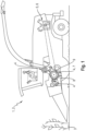
- FIG. 1 shows a schematic and exemplary representation of a self-propelled agricultural harvesting machine 1 according to the invention in the form of a forage harvester 2, which carries out a work order or harvesting order on an agricultural area 3.
- the body of the forage harvester 2 is shown cut open in its front part, below a driver's cab, in order to be able to show internal, crop-processing work units 4 of the forage harvester 2, which are also equipped with a FIG. 1 illustrated working unit 5 used for the drive, in the form of a drive motor 6, are connected.
- One of these work units 4 for processing crops is a so-called chopper 7 with a knife drum 8, which in turn is provided with a large number of chopping knives 9 distributed along its circumference.
- the present invention is not limited to a forage harvester 2, but is also equally suitable for other self-propelled harvesters 1, for example a combine harvester. Here and preferably it is a forage harvester 2.
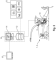
- the harvesting machine 1 further comprises at least one sensor device 10 and a position determining device 11, as in FIG. 2 shown.
- the sensor device 10 and the position determination device 11 are each connected to a database 12 or communicate with the database 12 for the transmission of data, so that the data determined by the sensor device 10 and the position determination device 11 can be transmitted to the database 12 and stored in it .
- the database 12 can be designed as a cloud-based database. Furthermore, it is possible for the database 12 to be designed centrally or decentrally, for example as a blockchain database. In addition to the data from the sensor device 10 and the position determination device 11, so-called reference data 13 can also be stored in the database 12.
- the database 12 is further connected to a processing device 14 or communicates with the processing device 14 for the transmission of data.
- a display device 15 can in turn be connected to the processing device 14 or the processing device 14 can communicate with the display device 15 to transmit data.
- the communication of the various devices 10, 11, 12, 14, 15 with one another for the transmission of data can either be wired and/or wireless.
- the wear of a working unit 4, 5 of a harvesting machine 1 can not only result in a defect or failure of the working unit 4, 5 or the harvesting machine 1, but also for the billing of work orders, the planning of a cultivation and /or harvesting strategy, the maintenance of the working unit or the harvesting machine and/or be or will be relevant for an obligation to provide proof.
- the method according to the invention now provides that initially by means of the at least one sensor device 10 of the harvesting machine 1 at a plurality of times t 1,...,n before, during and/or after the execution of a work order on the agricultural area 3 the harvester 1 operating data of the at least one working unit 4, 5 are determined.
- This operating data is transmitted from the sensor device 10 to the database 12, with transmission preferably being carried out at each time t of the plurality of times t 1,...,n at which the operating data was determined by the sensor device 10.
- the operating data can also be collected and transmitted to the database 12 after the work order has been completed.
- position data of the harvesting machine 1 is determined by means of the position determination device 11 of the harvesting machine 1 at the plurality of times t 1,...,n before, during and/or after the harvesting machine 1 carries out the work order on the agricultural area 3.
- This position data is transmitted from the position determination device 11 to the database 12, a transmission preferably being carried out at each time t of the plurality of times t 1,...,n at which the position data was determined by the position determination device 11.
- the position data can also be transmitted collectively to the database 12 after the work order has been completed.
- Both the operating data and the position data at each time t of the large number of times t 1,...,n are stored in the database 12 after they have been transmitted.
- the operating data and position data are assigned to each other and stored in the database 12.
- the assignment of operating data and position data can be done by providing each data value with a time stamp that represents the time t of the plurality of times t 1,...,n .
- the processing device 14 the operating data and position data stored in the database 12 are processed in an analysis routine in such a way that a location-referenced state of wear of the work unit 4, 5 is determined at each time t of the large number of times t 1,...,n .
- a state of wear of the working unit 4, 5 is determined at each time t of the plurality of times t 1,...,n , whereby the specific state of wear at a time t has a clear reference to a location or a position of the harvester 1 on the agricultural area 3 at this time t, i.e. a unique location reference.
- the processing device 14 determines the state of wear by processing the determined data in an analysis routine.
- the analysis routine uses an analysis algorithm, by means of which the operating data of the working unit 4, 5 determined by the sensor device 10 and the position data of the harvesting machine 1 determined by the position determining device 11 are processed in such a way that the state of wear of the Working unit 4, 5 is determined.
- the state of wear of the working unit 4, 5 can be determined by means of the processing device 14, for example in % wear, with 0% wear defining no wear of the working unit 4, 5 and 100% wear defining the achievement of the maximum service life of the working unit 4, 5.
- the processing device 14 is also designed to detect an operationally critical state of wear of the work unit 4, 5, for example from one Value greater than 60% wear could exist, in which the specific location-referenced wear condition is compared with a limit value stored in the database 12, which defines an operationally critical wear condition.
- the aforementioned reference data 13 stored in the database 12 are preferably used as the input variable of the analysis algorithm.
- reference data 13 characteristic map data of the working unit 4, 5 and/or the harvesting machine 1, historical data on wear conditions of the working unit 4, 5, geometry data of the working unit 4, 5 and/or the harvesting machine 1, load spectra of the working unit 4, 5 and/or the Harvesting machine 1, weather data and / or agronomic data of the agricultural area 3, in particular floor slabs, inventory data, yield data and / or area data.
- the analysis algorithm used in the analysis routine by the processing device 14 can be a learning analysis algorithm, i.e. an analysis algorithm that is based on artificial intelligence, preferably an artificial neural network.
- the adaptive analysis algorithm is trained using an initial data set which defines assignments made by means of manual annotation of various operating parameters of work units 4, 5 and corresponding wear states of the work units 4, 5.
- the data and certain wear conditions determined while carrying out the method according to the invention can be used to further train the analysis algorithm.
- the processing device 14 depending on the location-referenced state of wear of the work unit 4, 5, the costs caused by wear when carrying out the work order, a cause for the wear, a future cultivation strategy on the agricultural area 3, a future harvest strategy for the agricultural area 3 and / or a maintenance interval of the working unit 4, 5 can be determined.
- the display or representation of this information on the display device 15 can optionally be text-based and/or graphic, in particular using graphic elements and/or color highlighting.
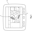
- a course of these location-referenced wear conditions of the work unit 4, 5 can also be displayed, preferably graphically. Furthermore, it is possible for the specific location-referenced wear conditions of the at least one work unit 4, 5 to be mapped or displayed using the display device 15. In other words, by means of the display direction 15, a map of the agricultural area 3 is shown or displayed, on which the specific wear conditions of the working unit 4, 5 are each assigned to an area of the agricultural area 3. FIG. 3 shows such a mapping of the specific wear conditions shown by the display device 15. In the FIG.
- the map shown by means of the display device 15 shows two agricultural areas 3, each of the two agricultural areas 3 being divided into several area areas, the boundaries of which are defined by fine lines on the map.
- the hatching or coloring of each surface area reflects the wear caused by the processing of this surface area on the work unit 4, 5 or a change in the state of wear that arose from the processing of this surface area. Based on this, the person, for example a farmer or contractor, to whom the map is displayed using the display device 15, can directly assess the work order carried out on the corresponding agricultural area 3.
- further information can be displayed, such as the costs caused by wear when carrying out the work order, a cause for the wear, a future cultivation strategy on the corresponding agricultural area 3, a future harvesting strategy for the corresponding agricultural area 3, a maintenance interval of the working unit 4, 5 and/or information about the working unit 4, 5 of the harvesting machine 1, the state of wear of which is being considered.
- a location-referenced wear index can be determined by the processing device 14 based on the determination of a location-referenced wear state of the work unit 4, 5 at the plurality of times t 1,...,n carried out by the processing device 14.
- a location-referenced state of wear of the work unit 4, 5 determined at a time t 1 immediately before the work order is carried out by the harvester 1 using the processing device 14 is included a locally referenced state of wear of the work unit 4, 5 determined at a time t n immediately after the work order has been carried out by the harvester 1 by means of the processing device 14 and based on this comparison, the locally referenced wear index for the work unit 4, 5 is determined by means of the processing device 14.
- the location-referenced wear index represents the wear of the work unit 4, 5 that occurred when the harvester 1 carried out the work order on the agricultural area 3.
- the location-referenced wear index determined by the processing device 14 is stored in the database 12.
- the location-referenced wear index for the work unit 4, 5 determined by the processing device 14 can be used or processed to determine the costs caused by wear and tear when the harvesting machine 1 carries out the work order.
- the location-referenced wear index can be used to determine which costs were incurred when and where on the agricultural area 3 when the work order was carried out by the harvesting machine 1. These costs can be used as a basis for determining the operating costs incurred by the harvester 1 for carrying out the work order.
- the location-referenced wear index for the working unit 4, 5 determined by the processing device 14 can be used or processed to determine a maintenance interval for the working unit 4, 5, whereby the maintenance of the working unit 4, 5 or the harvesting machine 1 can be planned in an efficient manner.
- the processing device 14 By means of the processing device 14, not only the location-referenced state of wear of a working unit 4, 5 of the harvesting machine 1 can be determined. Rather, the state of wear of a large number of working units 4, 5 of the harvesting machine 1 can be determined at the same time. For this purpose, operating data from a large number of work units 4, 5 of the harvesting machine 1 are collected by means of a large number of sensor devices 10 of the harvesting machine 1 at the large number of times t 1,...,n before, during and/or after the harvesting machine 1 carries out the work order certainly.
- the processing device 14 Based on this large number of operating data and the position data, which were determined by means of the position determining device 11 at the large number of times t 1,..., n before, during and/or after the harvesting machine 1 carried out the work order, the processing device 14 a location-referenced state of wear of each work unit 4, 5 of the large number of work units 4, 5 is determined at the corresponding time t. Based on the location-referenced Wear conditions of each work unit 4, 5 of the large number of work units 4, 5 can also be determined by means of the processing device 14, a wear state of the harvesting machine 1 as a whole.
- the processing device 14, the database 12 and/or the display device 15 can each be designed as an external device or as a device assigned to the harvester 1. If the processing device 14 and the database 12 are designed as external devices, they can together form a management system 16.
- a management system 16 may be assigned to an entity, for example a service provider, which is independent of a person, for example a farmer or a contractor, who is assigned to the harvester 1 or the agricultural area 3 on which the work order is carried out.
- Use of the administration system 16 to carry out the procedure can be activated by the entity, i.e. the service provider, if authorization is available.
- the person can have the service provider activate the use of the administration system 16 to carry out the method according to the invention by paying a fee.
- the implementation of the method according to the invention is then offered as a paid external service, i.e. as an as-a-service functionality.
- the harvesting machine 1 can automatically generate an instruction relating to the operation of the harvesting machine 1 by means of the processing device 14 based on the specific location-dependent state of wear at times t 1,...,n .
- the processing device 14 it would be possible for the processing device 14 to automatically stop or switch off the work unit 4, 5 when determining a critical state of wear of the work unit 4, 5 during the execution of the work order and/or to switch off certain functions of the harvesting machine 1 required for the execution of the work order .
- the harvesting machine 1 to automatically order maintenance of the working unit 4, 5 by means of the processing device 14 when determining a critical state of wear of the working unit 4, 5.
- the sensor device 10 is an inductively operating sensor device 10, which is arranged in the area of a knife drum 8 of a chopper 7 of the forage harvester 2, which is provided with a large number of chopping knives 9.
- a location-related state of wear of one or more chopping knives 9 of the knife drum 8 is determined at each time t of the large number of times t 1,...,n based on the recorded operating data of the inductively operating sensor device 10 and the position data of the forage harvester 2 .
Landscapes
- Life Sciences & Earth Sciences (AREA)
- Environmental Sciences (AREA)
- Management, Administration, Business Operations System, And Electronic Commerce (AREA)
Applications Claiming Priority (1)
| Application Number | Priority Date | Filing Date | Title |
|---|---|---|---|
| DE102022121398.6A DE102022121398A1 (de) | 2022-08-24 | 2022-08-24 | Verfahren zum Bestimmen eines Verschleißzustands einer selbstfahrenden landwirtschaftlichen Erntemaschine |
Publications (2)
| Publication Number | Publication Date |
|---|---|
| EP4331344A1 true EP4331344A1 (fr) | 2024-03-06 |
| EP4331344B1 EP4331344B1 (fr) | 2026-04-15 |
Family
ID=86851343
Family Applications (1)
| Application Number | Title | Priority Date | Filing Date |
|---|---|---|---|
| EP23179441.3A Active EP4331344B1 (fr) | 2022-08-24 | 2023-06-15 | Procédé de détermination d'un état d'usure d'une moissonneuse agricole automotrice |
Country Status (2)
| Country | Link |
|---|---|
| EP (1) | EP4331344B1 (fr) |
| DE (1) | DE102022121398A1 (fr) |
Citations (3)
| Publication number | Priority date | Publication date | Assignee | Title |
|---|---|---|---|---|
| EP2225931A1 (fr) * | 2009-03-02 | 2010-09-08 | CLAAS Selbstfahrende Erntemaschinen GmbH | Moissonneuse agricole |
| DE102017103537A1 (de) | 2017-02-21 | 2018-08-23 | Claas Selbstfahrende Erntemaschinen Gmbh | Erfassungsanordnung zur Erfassung eines Verschleißzustands eines Häckselwerks |
| EP3970467A1 (fr) * | 2020-09-15 | 2022-03-23 | Deere & Company | Analyse sonore pour identifier un composant endommagé dans une machine de travail |
-
2022
- 2022-08-24 DE DE102022121398.6A patent/DE102022121398A1/de active Pending
-
2023
- 2023-06-15 EP EP23179441.3A patent/EP4331344B1/fr active Active
Patent Citations (3)
| Publication number | Priority date | Publication date | Assignee | Title |
|---|---|---|---|---|
| EP2225931A1 (fr) * | 2009-03-02 | 2010-09-08 | CLAAS Selbstfahrende Erntemaschinen GmbH | Moissonneuse agricole |
| DE102017103537A1 (de) | 2017-02-21 | 2018-08-23 | Claas Selbstfahrende Erntemaschinen Gmbh | Erfassungsanordnung zur Erfassung eines Verschleißzustands eines Häckselwerks |
| EP3970467A1 (fr) * | 2020-09-15 | 2022-03-23 | Deere & Company | Analyse sonore pour identifier un composant endommagé dans une machine de travail |
Also Published As
| Publication number | Publication date |
|---|---|
| EP4331344B1 (fr) | 2026-04-15 |
| DE102022121398A1 (de) | 2024-02-29 |
Similar Documents
| Publication | Publication Date | Title |
|---|---|---|
| EP3626041B1 (fr) | Système de travail agricole | |
| EP2987396B1 (fr) | Systeme d'assistance du conducteur pour engin agricole | |
| EP3666050A1 (fr) | Système de travail agricole | |
| DE102013106128A1 (de) | Landwirtschaftliche Arbeitsmaschine mit zumindest einer Steuerungseinrichtung | |
| EP2132974A1 (fr) | Moissonneuse agricole | |
| EP2728523A1 (fr) | Système d'assistance pour l'optimisation du fonctionnement d'un véhicule | |
| DE102013106131A1 (de) | Fahrerassistenzsystem für landwirtschaftliche Arbeitsmaschine | |
| DE102018104287A1 (de) | Feldhäcksler und Verfahren zum Betreiben eines Feldhäckslers | |
| EP3424292B1 (fr) | Procédé d'analyse de l'état de fonctionnement d'une barre de coupe et barre de coupe | |
| DE102007022899A1 (de) | Landwirtschaftliche Arbeitsmaschine | |
| DE102013106133A1 (de) | Selbstfahrende landwirtschaftliche Arbeitsmaschine | |
| DE102019203247A1 (de) | Vision-basiertes Lenkungsassistenzsystem für Landfahrzeuge | |
| EP3777499A1 (fr) | Tracteur agricole | |
| EP2130422B1 (fr) | Véhicule automobile destiné au traitement de surfaces agricoles et procédé de fonctionnement d'un véhicule automobile destiné au traitement de surfaces agricoles | |
| EP4331344B1 (fr) | Procédé de détermination d'un état d'usure d'une moissonneuse agricole automotrice | |
| EP4508973A1 (fr) | Procédé de détermination d'un état d'usure d'une presse à balles agricole | |
| EP3718391B1 (fr) | Ramasseuse-hacheuse | |
| EP4268558A1 (fr) | Système d'assistance pour générer des plans de route pour des machines agricoles autonomes | |
| EP4331343A1 (fr) | Procédé de détermination optimisée de paramètres de machine d'une machine de travail agricole | |
| EP4270135A1 (fr) | Système d'assistance pour générer des limites de champ virtuel pour des machines agricoles autonomes | |
| EP4268563B1 (fr) | Procédé de détermination d'un état d'usure d'une machine de travail agricole autonome | |
| EP2857919B1 (fr) | Système de commande du fonctionnement d'un véhicule utilitaire agricole | |
| DE102023106996A1 (de) | Verfahren zur Zustandserkennung von Bodenbearbeitungswerkzeugen an einem Bodenbearbeitungsgerät | |
| DE102023121739A1 (de) | Assistenzsystem für ein landwirtschaftliches Gespann | |
| EP3229200A1 (fr) | Système d'administration de données de travail et de données opérationnelles d'au moins une machine agricole |
Legal Events
| Date | Code | Title | Description |
|---|---|---|---|
| PUAI | Public reference made under article 153(3) epc to a published international application that has entered the european phase |
Free format text: ORIGINAL CODE: 0009012 |
|
| STAA | Information on the status of an ep patent application or granted ep patent |
Free format text: STATUS: THE APPLICATION HAS BEEN PUBLISHED |
|
| AK | Designated contracting states |
Kind code of ref document: A1 Designated state(s): AL AT BE BG CH CY CZ DE DK EE ES FI FR GB GR HR HU IE IS IT LI LT LU LV MC ME MK MT NL NO PL PT RO RS SE SI SK SM TR |
|
| P01 | Opt-out of the competence of the unified patent court (upc) registered |
Effective date: 20240306 |
|
| STAA | Information on the status of an ep patent application or granted ep patent |
Free format text: STATUS: REQUEST FOR EXAMINATION WAS MADE |
|
| 17P | Request for examination filed |
Effective date: 20240906 |
|
| RBV | Designated contracting states (corrected) |
Designated state(s): AL AT BE BG CH CY CZ DE DK EE ES FI FR GB GR HR HU IE IS IT LI LT LU LV MC ME MK MT NL NO PL PT RO RS SE SI SK SM TR |
|
| GRAP | Despatch of communication of intention to grant a patent |
Free format text: ORIGINAL CODE: EPIDOSNIGR1 |
|
| STAA | Information on the status of an ep patent application or granted ep patent |
Free format text: STATUS: GRANT OF PATENT IS INTENDED |
|
| INTG | Intention to grant announced |
Effective date: 20251114 |
|
| GRAS | Grant fee paid |
Free format text: ORIGINAL CODE: EPIDOSNIGR3 |
|
| GRAA | (expected) grant |
Free format text: ORIGINAL CODE: 0009210 |
|
| STAA | Information on the status of an ep patent application or granted ep patent |
Free format text: STATUS: THE PATENT HAS BEEN GRANTED |
|
| AK | Designated contracting states |
Kind code of ref document: B1 Designated state(s): AL AT BE BG CH CY CZ DE DK EE ES FI FR GB GR HR HU IE IS IT LI LT LU LV MC ME MK MT NL NO PL PT RO RS SE SI SK SM TR |
|
| REG | Reference to a national code |
Ref country code: CH Ref legal event code: F10 Free format text: ST27 STATUS EVENT CODE: U-0-0-F10-F00 (AS PROVIDED BY THE NATIONAL OFFICE) Effective date: 20260415 |