EP4331404A1 - Unité source d'alimentation d'inhalateur - Google Patents
Unité source d'alimentation d'inhalateur Download PDFInfo
- Publication number
- EP4331404A1 EP4331404A1 EP22795352.8A EP22795352A EP4331404A1 EP 4331404 A1 EP4331404 A1 EP 4331404A1 EP 22795352 A EP22795352 A EP 22795352A EP 4331404 A1 EP4331404 A1 EP 4331404A1
- Authority
- EP
- European Patent Office
- Prior art keywords
- control unit
- power source
- panel
- mode
- unit
- Prior art date
- Legal status (The legal status is an assumption and is not a legal conclusion. Google has not performed a legal analysis and makes no representation as to the accuracy of the status listed.)
- Pending
Links
Images






Classifications
-
- A—HUMAN NECESSITIES
- A24—TOBACCO; CIGARS; CIGARETTES; SIMULATED SMOKING DEVICES; SMOKERS' REQUISITES
- A24F—SMOKERS' REQUISITES; MATCH BOXES; SIMULATED SMOKING DEVICES
- A24F40/00—Electrically operated smoking devices; Component parts thereof; Manufacture thereof; Maintenance or testing thereof; Charging means specially adapted therefor
- A24F40/50—Control or monitoring
- A24F40/53—Monitoring, e.g. fault detection
-
- A—HUMAN NECESSITIES
- A24—TOBACCO; CIGARS; CIGARETTES; SIMULATED SMOKING DEVICES; SMOKERS' REQUISITES
- A24F—SMOKERS' REQUISITES; MATCH BOXES; SIMULATED SMOKING DEVICES
- A24F40/00—Electrically operated smoking devices; Component parts thereof; Manufacture thereof; Maintenance or testing thereof; Charging means specially adapted therefor
- A24F40/50—Control or monitoring
-
- A—HUMAN NECESSITIES
- A24—TOBACCO; CIGARS; CIGARETTES; SIMULATED SMOKING DEVICES; SMOKERS' REQUISITES
- A24F—SMOKERS' REQUISITES; MATCH BOXES; SIMULATED SMOKING DEVICES
- A24F40/00—Electrically operated smoking devices; Component parts thereof; Manufacture thereof; Maintenance or testing thereof; Charging means specially adapted therefor
- A24F40/10—Devices using liquid inhalable precursors
-
- A—HUMAN NECESSITIES
- A24—TOBACCO; CIGARS; CIGARETTES; SIMULATED SMOKING DEVICES; SMOKERS' REQUISITES
- A24F—SMOKERS' REQUISITES; MATCH BOXES; SIMULATED SMOKING DEVICES
- A24F40/00—Electrically operated smoking devices; Component parts thereof; Manufacture thereof; Maintenance or testing thereof; Charging means specially adapted therefor
- A24F40/40—Constructional details, e.g. connection of cartridges and battery parts
-
- A—HUMAN NECESSITIES
- A24—TOBACCO; CIGARS; CIGARETTES; SIMULATED SMOKING DEVICES; SMOKERS' REQUISITES
- A24F—SMOKERS' REQUISITES; MATCH BOXES; SIMULATED SMOKING DEVICES
- A24F40/00—Electrically operated smoking devices; Component parts thereof; Manufacture thereof; Maintenance or testing thereof; Charging means specially adapted therefor
- A24F40/50—Control or monitoring
- A24F40/51—Arrangement of sensors
-
- A—HUMAN NECESSITIES
- A24—TOBACCO; CIGARS; CIGARETTES; SIMULATED SMOKING DEVICES; SMOKERS' REQUISITES
- A24F—SMOKERS' REQUISITES; MATCH BOXES; SIMULATED SMOKING DEVICES
- A24F40/00—Electrically operated smoking devices; Component parts thereof; Manufacture thereof; Maintenance or testing thereof; Charging means specially adapted therefor
- A24F40/20—Devices using solid inhalable precursors
-
- A—HUMAN NECESSITIES
- A24—TOBACCO; CIGARS; CIGARETTES; SIMULATED SMOKING DEVICES; SMOKERS' REQUISITES
- A24F—SMOKERS' REQUISITES; MATCH BOXES; SIMULATED SMOKING DEVICES
- A24F40/00—Electrically operated smoking devices; Component parts thereof; Manufacture thereof; Maintenance or testing thereof; Charging means specially adapted therefor
- A24F40/60—Devices with integrated user interfaces
Definitions
- the present invention relates to an inhaler power source unit.
- An inhaler such as a heated tobacco product can include a base material including an aerosol source and a flavor source, and a power source unit that accommodates the base material and heats the base material by supplying electric power from a power supply to a heater.
- the power source unit is a portion held by a user at the time of use, and can include an operation unit and a display unit.
- PTL 1 discloses an aerosol supply system in which a detachable member (panel) is attached to the surface of an assembly corresponding to a power source unit.
- PTL 1 Japanese Patent Laid-Open No. 2021-500032
- the present invention provides an inhaler power source unit, for example, advantageous in both safety and user convenience.
- an inhaler power source unit that supplies electric power from a power supply to a heater configured to heat an aerosol source, characterized by comprising a control unit configured to control an operation of the power source unit, a housing configured to accommodate the power supply and the control unit, a panel configured to be detachably attached to a surface of the housing, and a detection unit configured to detect attachment or detachment of the panel to or from the housing, wherein the control unit is configured to impose, in a case where the detection unit detects the detachment of the panel, a function restriction on a plurality of functions controlled by the control unit, and the control unit has a plurality of operation modes, and contents of the function restriction are different for each operation mode.
- the power source unit further comprises an operation button arranged in the housing, wherein in any of the plurality of operation modes, in a state in which the panel is detached, the control unit disables an operation of the operation button as the function restriction.
- the power source unit further comprises a display unit, wherein the plurality of operation modes include a standby mode of standing by for detection of an unlock operation using the operation button while performing display by the display unit, and an aerosol generation mode of supplying electric power to the heater to generate aerosol, and in a case where the unlock operation is detected in the state in which the panel is detached in the standby mode, the control unit does not transition to the aerosol generation mode as the function restriction.
- the plurality of operation modes include a standby mode of standing by for detection of an unlock operation using the operation button while performing display by the display unit, and an aerosol generation mode of supplying electric power to the heater to generate aerosol, and in a case where the unlock operation is detected in the state in which the panel is detached in the standby mode, the control unit does not transition to the aerosol generation mode as the function restriction.
- the control unit prohibits supplying the electric power to the heater as the function restriction.
- the control unit cancels the prohibition of supplying the electric power to the heater.
- the plurality of operation modes further include a sleep mode of stopping the display by the display unit and standing by in a power saving state in a case where a non-operation state in which no user operation is performed on the power source unit continues in the standby mode for a predetermined time, and a pairing mode capable of executing paring for associating the power source unit with an external communication device, and in a case where a pairing operation using the operation button is detected in the sleep mode in the state in which the panel is detached, the control unit does not transition to the pairing mode as the function restriction.
- the control unit prohibits executing the pairing as the function restriction.
- the plurality of operation modes further include an unlock setting mode capable of executing, in response to execution of an unlock setting operation using the operation button, setting of the unlock operation, and in a case where the unlock setting operation using the operation button is detected in the state in which the panel is detached, the control unit does not transition to the unlock setting mode as the function restriction.
- the control unit prohibits executing the setting of the unlock operation.
- the plurality of operation modes further include a charging mode of charging the power supply using an external power supply, and even in a case where the detection unit detects the detachment of the panel in the charging mode, the control unit continues charging the power supply.
- the control unit continues the display by the display unit.
- the power source unit further comprises a setting unit configured to set contents of the function restriction on the plurality of functions.
- an inhaler power source unit for example, advantageous in both safety and user convenience can be provided.
- Figs. 1A and 1B show an example of the outer appearance of an inhaler 100 according to an embodiment.
- the inhaler 100 provides, to a user via a stick 110, flavored aerosol, a gas containing aerosol and a flavor material, aerosol, or aerosol containing a flavor material in accordance with an operation of requesting aerosol (to be also referred to as an "aerosol generation request" hereinafter) such as an inhalation operation by the user. Therefore, the inhaler 100 may be understood as an aerosol generation device.
- the inhaler 100 can be formed by a power source unit 101 and the stick 110.
- the stick 110 is, for example, a base material including an aerosol source and a flavor source.
- the aerosol source can be, for example, a liquid such as a polyhydric alcohol such as glycerin or propylene glycol. Alternatively, the aerosol source may contain a drug.
- the aerosol source may be a liquid, a solid, or a mixture of a liquid and a solid.
- a vapor source such as water may be used in place of the aerosol source.
- the flavor source can be, for example, a formed body obtained by forming a tobacco material. Alternatively, the flavor source may be formed by a plant (for example, mint, herb, Chinese medicine, coffee beans, or the like) other than tobacco.
- a fragrance such as menthol may be added to the flavor source.
- the flavor source may be added to the aerosol source.
- the power source unit 101 has a substantially rectangular parallelopiped shape with round corners that is elongated in the vertical direction of the sheet surface of each of Figs. 1A and 1B , and can be formed in a size which the user can grasp with one hand.
- the power source unit 101 can include an outer panel 102, an action button B, and a slider 105.
- the outer panel 102 is a flexible panel member that covers at least part of the front surface of the power source unit 101.
- the outer panel 102 is an exterior member of the power source unit 101, that is detachable for replacement, and may be understood as a decorative panel. For example, a plurality of outer panels different in color and pattern are prepared, and the user can replace the outer panel by a preferred outer panel.
- the outer panel 102 may be understood as a heat-insulating panel that insulates heat generated in the power source unit 101, or as a protection panel that protects the inside of the power source unit 101 from an impact or compression at the time of falling.
- a display window 103 is formed in the outer panel 102.
- the display window 103 can be a band-like window extending along the longitudinal direction (the vertical direction of the sheet surface) in substantially the center of the outer panel 102.
- the power source unit 101 includes a display D (display unit) (see Fig. 2 ).
- the display D can include, for example, one or more LEDs (Light-Emitting Diodes). Light emitted by the LED passes through the display window 103.
- the display D can display, for example, a residual battery amount by a bar graph.
- the action button B is an operation button formed by a physical push button.
- the action button B is covered with the outer panel 102. However, since the outer panel 102 is flexible, the user can operate the action button B via the outer panel 102. When the user presses the action button B via the outer panel 102, a corresponding signal is transmitted to a control unit (to be described later).
- a control unit to be described later.
- this embodiment will describe, as an example, a case where the action button B formed by a physical button is covered with the outer panel 102 but another arrangement may be adopted as long as a user operation can be accepted.
- another arbitrary type of input device such as a switch or a touch sensing surface exposed from the outer panel 102 may be provided.
- the outer panel 102 may be imparted with such rigidity that the user needs to push the outer panel 102 using a plurality of fingers to operate the action button B via the outer panel 102. This can prevent, for example, the action button B from being erroneously pressed in a bag or an unintended erroneous operation by the user. This is also advantageous in terms of prevention of child mischief (child resistance).
- the slider 105 is a cover member (shutter) slidably disposed on the upper surface of the power source unit 101 along a direction 105a indicated by an arrow.
- the slider 105 is configured to open/close an opening into which the stick 110 is inserted.
- Fig. 1A shows a state in which an opening 106 is covered with the slider 105. This state will also be referred to as a "shutter closed state” hereinafter.
- Fig. 1B shows a state in which the opening 106 is exposed by sliding the slider 105 to the near side. This state will also be referred to as a "shutter open state” hereinafter.
- the user When inhaling aerosol using the inhaler 100, the user operates the slider 105 to the shutter open state. After that, the user inserts the stick 110 into the opening 106.
- the inserted stick 110 is held by a tubular holding portion 107 communicating with the opening 106.
- a section perpendicular to the longitudinal direction of the holding portion 107 can be, for example, circular, elliptical, or polygonal, and the sectional area of the section gradually reduces toward the bottom surface.
- the inner surface of the holding portion 107 pushes the outer surface of the stick 110 inserted into the holding portion 107, thereby making it possible to prevent a fall of the stick 110 by the frictional force.
- the user can perform an unlock operation using the action button B.
- the power source unit 101 is unlocked to start heating the stick 110, thereby setting an inhalation enable state.
- the inhalation enable state is thus set, the user can hold, in the mouth, a mouthpiece portion formed at the distal end of the stick 110 and inhale flavored aerosol. After the end of the inhalation of the aerosol, the user performs an operation of pulling out the stick 110 from the holding portion 107, and closing the slider 105 (shutter closed state).
- Fig. 2 is a view showing the internal arrangement of the inhaler 100. Note that Fig. 2 does not illustrate the outer panel 102.
- the power source unit 101 includes the holding portion 107 that communicates with the opening 106 and holds the stick 110.
- the power source unit 101 can include a heater H, an electrical component E, and a user interface 116.
- the user interface 116 may be understood to be included in the electrical component E.
- the heater H forms a heating unit that heats the stick 110.
- the heater H can include, for example, a resistive heat generating component that generates aerosol by heating an aerosol source included in the stick 110.
- the heater H is arranged to cover the periphery of the holding portion 107, and generates heat by electric power supplied from the electrical component E.
- the heat of the heater H is transmitted to the stick 110 via the holding portion 107, thereby heating the stick 110.
- the stick 110 When the stick 110 is heated, the stick 110 generates aerosol.
- the user interface 116 can include the action button B, the display D, and a vibration generation unit V
- the vibration generation unit V can be formed by a vibration motor (vibrator) for vibrating the housing of the power source unit 101. By vibrating the housing by the vibration motor, it is possible to notify the user, who holds the power source unit 101, of the state.
- the vaporized and/or aerosolized aerosol source is transported toward the mouthpiece portion by air.
- the vaporized and/or aerosolized aerosol source is cooled to form fine liquid droplets, thereby promoting aerosolization.
- the flavor source is also included in the stick 110, a flavor material generated from the flavor source is added to the aerosol, and the resultant flavored aerosol is transported to the mouthpiece portion, and inhaled by the user's mouth.
- Fig. 3A is a view showing the inner surface of the outer panel 102.
- Fig. 3B is a view showing a portion exposed to the front surface of the power source unit 101 in a state in which the outer panel 102 is detached.
- the power source unit 101 includes a housing 101a that accommodates a power supply and an electric component (including a control unit to be described later), and an inner panel 202.
- the inner panel 202 is arranged around the action button B to expose the action button B, and is arranged to cover the front surface of the housing 101a.
- the inner surface of the outer panel 102 and the outer surface of the inner panel 202 face each other.
- a magnet 11 is arranged above the display window 103, a projection 12 is arranged below the display window 103, and magnets 13A and 14 are arranged below the projection 12.
- the magnetic force magnetic attraction force
- the magnets 11 and 14 attracts the outer panel 102 to the inner panel 202. This causes the outer panel 102 to be held by the inner panel 202.
- the projection 12 is at such position facing the action button B that the action button B can be pressed.
- a magnetic sensor 23A is arranged on the rear surface of the inner panel 202.
- the magnet 13A is formed as a magnetic field application unit for the magnetic sensor 23A. When the magnetic sensor 23A detects a magnetic force by a magnetic field applied from the magnet 13A, it is possible to detect the attachment of the outer panel 102.
- a display window 25 is formed above the action button B, a magnet 21A is arranged above the display window 25, and a magnet 24 is arranged below the action button B.
- the magnetic sensor 23A is arranged at a position between the action button B and the magnet 24 on the inner surface (more correctly, on a substrate with an approximately zero distance to the inner surface) of the inner panel 202.
- the magnetic sensor 23A forms a magnetic force detection region 26A indicated by a broken line on the outer surface of the inner panel 202.
- the magnet 21A, the display window 25, the action button B, the magnetic sensor 23A, and the magnet 24 on the side of the inner panel 202 correspond to the magnet 11, the display window 103, the projection 12, the magnet 13A, and the magnet 14 on the side of the outer panel 102, respectively. That is, when the outer panel 102 is attached to the inner panel 202, the panels are aligned with respect to the respective components so that they face each other.
- the magnets 21A and 24 of the inner panel 202 can be attracted to the magnets 11 and 14 of the outer panel 102 by the magnetic forces (magnetic attraction forces), respectively. That is, when the magnets 11 and 21A are attracted to each other and the magnets 14 and 24 are attracted to each other, the inner panel 202 can hold the outer panel 102. Note that each of the magnets 11 and 14 of the outer panel 102 and the magnets 21A and 24 of the inner panel 202 can be formed by a permanent magnet.
- the action button B arranged in the central portion of the inner panel 202 is covered with the outer panel 102 when the outer panel 102 is attached to the inner panel 202.
- the user can press the action button B via the projection 12 of the outer panel 102 by pressing a portion around the central portion of the outer panel 102. This can switch, for example, power-on/off of the inhaler 100.
- the magnetic sensor 23A detects a magnetic force based on a magnetic field applied from the magnet 13A in the outer panel 102.
- the magnetic sensor 23A can be a Hall sensor formed using a Hall element. This can detect the attachment of the outer panel 102 to the inner panel 202. In the state in which the outer panel 102 is attached to the inner panel 202, light from the display D is transmitted through the display window 25 of the inner panel 202 and the display window 103 of the outer panel 102.
- the magnetic sensor 23A of the inner panel 202 is arranged to face the magnet 13A of the outer panel 102 via the inner surface of the inner panel 202 in the state in which the outer panel 102 is attached to the inner panel 202. That is, when the outer panel 102 is attached to the inner panel 202, the distance between the magnetic sensor 23A of the inner panel 202 and the magnet 13A of the outer panel 102 is minimum.
- the magnetic sensor 23A of the inner panel 202 is configured not to detect a magnetic field generated by each of the two magnets 21A and 24 of the inner panel 202.
- the magnetic sensor 23A is arranged at a position separated from the two magnets 21A and 24 on the outer surface of the inner panel 202. This can set the influence of the magnetic fields from the two magnets 21A and 24 on the magnetic sensor 23A to approximately zero.
- the distance between the magnetic sensor 23A and the magnet 24 (or the magnet 21A) of the inner panel 202 can be set to be larger than the distance between the magnetic sensor 23A and the magnet 13A in the state in which the outer panel 102 is attached to the inner panel 202.
- the outer panel 102 can be configured so that data measured by the magnetic sensor 23A changes depending on the type of the outer panel 102 when the outer panel 102 is attached to the inner panel 202. More specifically, the outer panel 102 is configured so that the magnitude of the magnetic force concerning the magnet 13A of the magnetic field application unit, which is detected by the magnetic sensor 23A of the inner panel 202, changes depending on the type of the panel.
- the outer panel 102 can be configured so that the distance between the magnet 13A as the magnetic field application unit and its facing magnetic sensor 23A changes depending on the type of the outer panel in the state in which the outer panel 102 is attached to the inner panel 202. That is, the shape of the curved surface may be adjusted for each type of outer panel so that the height of the inner surface of the outer panel 102 changes depending on the type. Note that those skilled in the art generally understand that the magnitude of the magnetic force changes depending on the distance from the magnet (more specifically, the magnitude of the magnetic force is inversely proportional to the square of the distance). Thus, it is possible to use the common magnet 13A in any type of the outer panel 102, which is advantageous in manufacturing.
- the position of the magnet 13A may be shifted so as to change depending on the type of the outer panel along the inner surface of the facing outer panel 102. This can change the distance between the magnet 13A and the magnetic sensor 23A in accordance with the type of the outer panel. That is, the magnitude of the magnetic force detected by the magnetic sensor 23A can be changed in accordance with the type of the panel.
- the outer panel 102 can be configured so that the type of the magnet 13A as the magnetic field application unit changes depending on the type of the outer panel.
- the magnet 13A is formed by, for example, a permanent magnet. More specifically, one of a Ferrite magnet, an Al-Ni-Co magnet, a cobalt magnet, a Neodymium magnet, and the like is selected in accordance with the type of the outer panel. This can change the magnitude of the magnetic force detected by the magnetic sensor 23A in accordance with the type of the outer panel.
- Figs. 4A and 4B show an arrangement example different from that shown in Figs. 3A and 3B .
- Fig. 4A is a view showing the inner surface of the outer panel 102.
- Fig. 4B is a view showing a portion exposed to the front surface of the power source unit 101 in a state in which the outer panel 102 is detached.
- Fig. 4B is a view of the outer appearance of the outer surface of the inner panel 202. In the state in which the outer panel 102 is attached to the power source unit 101, the inner surface of the outer panel 102 and the outer surface of the inner panel 202 face each other.
- a magnetic body 13B is arranged above the display window 103, the projection 12 is arranged below the display window 103, and a magnet 15 is arranged below the projection 12. Furthermore, the magnetic body 13B includes a circular base portion 11B, and a leg portion 12B that linearly extends from the base portion 11B approximately in the longitudinal direction.
- the magnetic body 13B is made of a material that becomes magnetized, when a magnetic field is applied from the outside, by the action of the magnetic field, and applies a magnetic field.
- the magnetic body 13B is formed as a magnetic field application unit for a magnetic sensor 23B (to be described later) of the inner panel 202.
- the magnetic body 13B can be made of, for example, a metal. More specifically, the magnetic body 13B can be made of a paramagnetic material or a ferromagnetic material as a non-permanent magnet. "Ferromagnetic” indicates the property of a material that becomes strongly magnetized, when a magnetic field is applied from the outside, in the same direction as that of the magnetic field, and is still magnetized even if the magnetic field from the outside is set to zero. Examples of the ferromagnetic material are iron, cobalt, and nickel.
- paramagnetic indicates the property of a material that becomes weakly magnetized, when a magnetic field is applied from the outside, in the same direction as that of the magnetic field, and is not magnetized when the magnetic field from the outside is set to zero.
- An example of the paramagnetic material is aluminum.
- the magnetic body 13B is formed as an acted upon unit that changes in a state (that is, is magnetized) in accordance with the action of a magnetic field applied from the outside.
- the magnetic body 13B is formed as a magnetic field application unit that applies a magnetic field to the inner panel 202. More specifically, if the outer panel 102 is attached to the inner panel 202, the magnetic body 13B functions as an acted upon unit that a magnet 21B of the inner panel 202 acts upon. As a result, the magnetic body 13B is magnetized, and functions as a magnetic field application unit for the magnet 21B and the magnetic sensor 23B of the inner panel 202.
- the outer panel 102 can be attracted to and held by the inner panel 202 by a magnetic force based on a magnetic field generated and applied by the magnetic body 13B (particularly, the base portion 11B). Furthermore, with respect to a magnetic field generated and applied by the magnetic body 13B (particularly, the leg portion 12B), the magnetic sensor 23B of the inner panel 202 can be made to detect the state of the leg portion 12B (that is, a magnetic force based on the magnetic field from the leg portion 12B). This can cause the power source unit 101 to detect the attachment of the outer panel 102.
- the display window 25 is formed above the action button B, the magnet 21B is arranged above the display window 25, and a magnet 27 is arranged below the action button B.
- the magnetic sensor 23B is arranged on a side of the display window 25 on the inner surface of the inner panel 202 (more correctly, on a substrate with an approximately zero distance to the inner surface).
- the magnetic sensor 23B forms a magnetic force detection region 26B indicated by a broken line on the outer surface of the inner panel 202.
- the magnet 21B, the magnetic sensor 23B, the display window 25, the action button B, and the magnet 27 on the side of the inner panel 202 correspond to the base portion 11B of the magnetic body 13B, the leg portion 12B of the magnetic body 13B, the display window 103, the projection 12, and the magnet 15 on the side of the outer panel 102, respectively. That is, when the outer panel 102 is attached to the inner panel 202, the panels are aligned with respect to the respective components so that they face each other. When the outer panel 102 is attached to the inner panel 202, they are arranged so that the magnetic body 13B of the outer panel 102 is aligned with both the magnet 21B and the magnetic sensor 23B of the inner panel 202.
- the outer panel 102 and the inner panel 202 are arranged so that the base portion 11B of the magnetic body 13B of the outer panel 102 is aligned with the magnet 21B of the inner panel 202 and the leg portion 12B of the magnetic body 13B of the outer panel 102 is aligned with the magnetic sensor 23B of the inner panel 202.
- the magnetic sensor 23B faces the leg portion 12B of the magnetic body 13B via the inner surface of the inner panel 202, and thus the distance between the magnetic sensor 23B and the leg portion 12B of the magnetic body 13B is minimum.
- the magnet 21B of the inner panel 202 is formed as an acting unit that generates a magnetic field.
- a magnetic force based on the magnetic field acts to magnetize the magnetic body 13B in the outer panel 102, thereby attracting the base portion 11B of the magnetic body. That is, the magnet 21B and the base portion 11B of the magnetic body 13B attract each other by the magnetic attraction force, and thus the inner panel 202 can hold the outer panel 102.
- the magnetic sensor 23B detects the magnetic force of the leg portion 12B of the magnetic body 13B magnetized in the outer panel 102.
- the magnetic sensor 23B can be a Hall sensor formed using a Hall element. This can detect the attachment of the outer panel 102 to the inner panel 202.
- the magnetic sensor 23B of the inner panel 202 is configured not to detect a magnetic field generated by each of the two magnets 21B and 27 of the inner panel 202.
- the magnetic sensor 23B is arranged at a position separated from the two magnets 21B and 27 on the outer surface of the inner panel 202. This can set the influence of the magnetic fields from the two magnets 21B and 27 on the magnetic sensor 23B to approximately zero.
- the distance between the magnetic sensor 23B and the magnet 21B (or the magnet 27) of the inner panel 202 can be set to be larger than the distance between the magnetic sensor 23B and the magnetic body 13B in the state in which the outer panel 102 is attached to the inner panel 202.
- the outer panel 102 can be configured so that data measured by the magnetic sensor 23B changes depending on the type of the outer panel 102 when the outer panel 102 is attached to the inner panel 202. More specifically, the outer panel 102 is configured so that data concerning the magnetized magnetic body 13B (that is, the magnitude of the magnetic force detected by the magnetic sensor 23B), which is detected by the magnetic sensor 23B of the inner panel 202, changes depending on the type of the panel.
- the outer panel 102 is configured so that the distance between the leg portion 12B of the magnetic body 13B and its facing magnetic sensor 23B changes depending on the type of the outer panel in the state in which the outer panel 102 is attached to the inner panel 202. That is, the shape of the curved surface may be adjusted for each type of panel so that the height of the inner surface of the outer panel 102 changes depending on the type.
- the common magnetic body 13B is used in any type of the outer panel 102, which is advantageous in manufacturing.
- the position of the magnetic body 13B may be shifted so as to change depending on the type of the panel along the inner surface of the facing outer panel 102. This can change the distance between the magnetic body 13B and the magnetic sensor 23B in accordance with the type of the panel. That is, the magnitude of the magnetic force detected by the magnetic sensor 23B can be changed in accordance with the type of the panel.
- FIG. 5 An example of the functional arrangement of the power source unit 101 will be described next with reference to Fig. 5 .
- functional blocks to be described may be integrated or separated, and each function to be described may be implemented by another block.
- a component to be described as a hardware component may be implemented by a software component and vice versa.
- a control unit 120 controls the operation of the power source unit 101.
- the control unit 120 may include one or more processors and a volatile memory.
- the processor may be, for example, a CPU (Central Processing Unit) or a microcontroller.
- the control unit 120 controls all the functions of the inhaler 100 by loading a computer program (also called software or firmware) stored in a storage unit 121 into the memory and executing the loaded program.
- the storage unit 121 can be, for example, a nonvolatile memory.
- the storage unit 121 stores one or more computer programs, and data describing a control sequence (heating profile) for controlling a heating unit 130.
- the heating unit 130 is a functional unit that heats the stick 110, and is formed by the above-described heater H.
- the control unit 120 can control communication (pairing or connection in a normal state) with an external communication device. Furthermore, the control unit 120 can control transition of the state of the inhaler 100 to be described later in accordance with a user operation on the action button B or the slider 105.
- the control unit 120 controls supply of electric power from a battery 132 to the heating unit 130. In response to an aerosol generation request, the control unit 120 can start to supply electric power from the battery 132 as a power supply to the heating unit 130.
- the control unit 120 controls the temperature of the heating unit 130 by adjusting the duty ratio of a control pulse by pulse width modulation (PWM). Note that the control unit 120 may use pulse frequency modulation (PFM) instead of PWM.
- PWM pulse width modulation
- An input detection unit 122 detects, for example, an operation input to the action button B.
- the input detection unit 122 detects a user operation performed by, for example, pushing the outer panel 102, and outputs an input signal indicating this user operation to the control unit 120.
- the inhaler 100 may detect pushing itself of the outer panel 102, instead of detecting the pressing of the action button B.
- a state detection unit 123 detects the open/closed state of the slider 105.
- the state detection unit 123 can be formed by, for example, a Hall sensor including a Hall element.
- the state detection unit 123 outputs, to the control unit 120, a state detection signal indicating whether the slider 105 is open or closed.
- the state detection unit 123 can also detect an attached/detached state of the outer panel 102. Therefore, the state detection unit 123 can include, for example, magnetic sensors 23A and 23B described above.
- the state detection unit 123 can output a state detection signal indicating the attached/detached state of the outer panel 102 to the control unit 120.
- An inhalation detection unit 124 can detect inhalation (puff) of the stick 110 by the user.
- the inhalation detection unit 124 can include a thermistor disposed near the opening 106.
- the inhalation detection unit 124 can detect inhalation by the user based on a change in resistance value of the thermistor resulting from a temperature change caused by the inhalation.
- the inhalation detection unit 124 may include a pressure sensor disposed on the bottom of the holding portion 107. In this case, the inhalation detection unit 124 can detect inhalation based on a reduction in atmospheric pressure resulting from an air current caused by the inhalation.
- the inhalation detection unit 124 outputs, to the control unit 120, for example, an inhalation detection signal indicating whether inhalation is performed.
- a light emitting unit 125 includes one or more LEDs and a driver for driving the LEDs, thereby forming the display D.
- the light emitting unit 125 turns on each LED in accordance with an instruction signal input from the control unit 120.
- a vibration unit 126 forms the above-described vibration generation unit V.
- the vibration unit 126 can include a vibrator (for example, an eccentric motor) and a driver for driving the vibrator.
- the vibration unit 126 vibrates the vibrator in accordance with an instruction signal input from the control unit 120.
- the control unit 120 may control at least one of the light emitting unit 125 and the vibration unit 126 in an arbitrary pattern, in order to notify the user of a certain status (for example, the status of pairing or detachment of the outer panel 102) of the inhaler 100.
- the light emission patterns of the light emitting unit 125 can be distinguished by elements such as the light emission state (always on/blinking/off), the blinking period, and the light color of each LED.
- the vibration patterns of the vibration unit 126 can be distinguished by elements such as the vibration state (vibration/stop) and the vibration strength of the vibrator.
- a communication I/F 127 includes, for example, a communication circuit and an antenna, and serves as a communication interface with which the inhaler 100 wirelessly communicates with an external communication device (for example, a smartphone, a personal computer, or a tablet terminal owned by the user).
- the communication I/F 127 can be, for example, an interface complying with an arbitrary wireless communication protocol, for example, short-range wireless communication such as Bluetooth ® , near-field wireless communication such as NFC (Near Field Communication), or a wireless LAN (Local Area Network).
- connection I/F 128 is a wired interface having a terminal for connecting the inhaler 100 to another external device.
- the connection I/F 128 can be a chargeable interface such as a USB (Universal Serial Bus) interface.
- the connection I/F 128 may be used to charge the battery 132 from an external power supply (charger) (via a feeder (not shown)).
- the battery 132 is a chargeable battery (secondary battery) such as a lithium-ion battery.
- the battery 132 may be formed by an electric double-layer capacitor such as a lithium-ion capacitor.
- a residual amount meter 133 can include an IC chip for monitoring the residual power amount and other statuses of the battery 132.
- the residual amount meter 133 can periodically measure the status values of the battery 132, such as the SOC (State Of Charge), the SOH (State Of Health), the RSOC (Relative SOC), and the power supply voltage, and can output the measurement results to the control unit 120.
- the control unit 120 has a plurality of operation modes.
- the plurality of modes can include, for example, a sleep mode 61, an active mode 62, an aerosol generation mode 63, a charging mode 64, an unlock setting mode 65, and a pairing mode 66.
- the sleep mode 61 is a state in which the operation by the control unit 120 is temporarily stopped to stand by in a power-saving state in which the power consumption is reduced.
- the speed mode is a state in which the inhaler 100 stops the main operation, and no electric power is supplied to the heater H. Display on the display D is not performed. In other words, in the sleep mode 61, the power source unit 101 is locked and the user cannot inhale aerosol.
- the control unit 120 can accept a predetermined user input, and can transition to another mode corresponding to the user input upon accepting the corresponding user input. Note that in the following description, the speed mode will sometimes be referred to as a standby state.
- the sleep mode 61 can be started by a method of "suspend” or “standby” by which the standby state begins while the contents of the memory of the control unit 120 are maintained, and can also be started by a method of "hibernation” by which the standby state begins while the contents of the memory of the control unit 120 are copied to the storage unit 121.
- functions need not be operable except for the function of detecting a user operation on the slider 105 or the action button B, and the function of monitoring the residual battery amount.
- the control unit 120 can transition to the active mode 62.
- the active mode 62 can be a standby mode of standing by for detection of an unlock operation using the action button B while performing at least display by the display D.
- the control unit 120 can return to the sleep mode 61 in which display on the display D is stopped to stand by in the power-saving state.
- the control unit 120 unlocks the locked state of the power source unit 101, and can transition to the aerosol generation mode 63 in which aerosol is generated.
- the unlock operation can be, for example, one pressing operation of the action button B. However, as will be described later, the unlock operation can be changed by setting.
- the unlock operation can be an operation of repeatedly pressing the action button B a predetermined number of times (for example, three times) within a predetermined time, an operation of pressing the action button B for a predetermined time (for example, 3 sec), or a combination thereof.
- the heating unit 130 performs heating (that is, supplies electric power to the heater H), and the user can inhale aerosol.
- the setting of the unlock operation may be disabled, and transition to the aerosol generation mode 63 may be performed in response to detection, by the inhalation detection unit 124 (puff sensor), of inhalation (puff) by the user.
- the control unit 120 can return to the active mode 62.
- the control unit 120 transitions to the charging mode 64 and the battery 132 is charged.
- the control unit 120 transitions to the sleep mode 61.
- the control unit 120 can transition to the unlock setting mode 65.
- the unlock operation is set.
- the unlock operation in a default state can be, for example, one pressing operation of the action button B.
- the unlock setting mode 65 the user can change this unlock operation to another operation.
- the unlock operation can be set to an arbitrary pattern such as an operation of repeatedly pressing the action button B a predetermined number of times within a predetermined time, an operation of pressing the action button B for a predetermined time, or a combination thereof. This can improve security performance of the power source unit 101.
- the control unit 120 returns to the charging mode 64. Note that in this embodiment, transition to the unlock setting mode 65 is performed from the charging mode 64 but transition to the unlock setting mode 65 may be performed from an operation mode other than the charging mode 64.
- the control unit 120 can transition to the pairing mode 66 for executing pairing with an external communication device. Pairing is processing of associating the power source unit 101 with an external communication device, and can be performed with, for example, the external communication device in compliance with Bluetooth'.
- the pairing operation can be, for example, an operation of pressing the action button B while the slider 105 is closed.
- the pairing mode 66 if pairing with the external communication device succeeds, the control unit 120 registers identification information of the paired device in a white list stored in the storage unit 121. If registration in the white list succeeds or pairing fails, the control unit 120 can transition from the pairing mode 66 to the sleep mode 61.
- Fig. 7 shows a control sequence in the sleep mode 61.
- the power source unit 101 is in the standby state.
- the control unit 120 determines whether the external power supply (charger) is connected to the connection I/F 128 to start charging of the battery 132. If charging is detected, the control unit 120 advances to step S104, and leaves the sleep mode 61 to transition to the active mode 62.
- the external power supply charger
- step S102 the control unit 120 determines the open/closed state of the slider 105 based on a state detection signal from the state detection unit 123. If the shutter open state is detected, the control unit 120 advances to step S103, and leaves the sleep mode 61 to transition to the active mode 62.
- step S105 the control unit 120 determines whether a pairing operation of pressing the action button B is performed in the shutter closed state (NO in step S102). If no pairing operation is detected, the process returns to step S101. On the other hand, if a pairing operation is detected, the control unit 120 transitions to the pairing mode (step S107). However, in this embodiment, in step S106, it is confirmed based on the output signal of the state detection unit 123 that the outer panel 102 is attached to the power source unit 101, and the control unit 120 advances to step S107, and transitions to the pairing mode. In step S106, if the outer panel 102 is detached from the power source unit 101, the control unit 120 does not transition to the pairing mode as the function restriction, and the process returns to step S101. At this time, the pairing operation may be disabled.
- Fig. 8 shows a control sequence in the active mode 62.
- the control unit 120 acquires the residual battery amount in step S201.
- the control unit 120 can acquire the residual battery amount based on the output voltage of the battery 132.
- the control unit 120 can acquire the residual battery amount based on the number of times of puff after the completion of charging, which is acquired from the inhalation detection unit 124.
- the power source unit 101 includes a management circuit that manages the battery 132
- the control unit 120 can acquire the residual battery amount based on an output from the management circuit.
- step S202 the control unit 120 determines whether the residual battery amount exceeds a predetermined threshold.
- step S205 the control unit 120 displays the residual battery amount on the display D.
- step S206 the control unit 120 determines whether a condition for returning to the sleep mode 61 is satisfied.
- the condition for returning to the sleep mode 61 can be, for example, a condition that the slider 105 is operated to be set in the shutter closed state or a condition that a non-operation period exceeds a predetermined time. If this condition is satisfied, the control unit 120 transitions to the sleep mode 61 in step S204.
- step S206 determines in step S207 whether an unlock operation is performed. If an unlock operation is detected, the control unit 120 determines in step S208 whether the outer panel 102 is attached to the power source unit 101. If the outer panel 102 is attached to the power source unit 101, the control unit 120 transitions to the aerosol generation mode 63 in step S209.
- step S210 a notification by the display D and/or the vibration generation unit V, and the process returns to step S201. That is, even if an unlock operation is detected in the state in which the outer panel 102 is detached, the control unit 120 does not transition to the aerosol generation mode 63 as the function restriction. At this time, the unlock operation may be disabled. Note that in this case, the control unit 120 may transition to the sleep mode 61 instead of returning to step S201.
- transition to the charging mode 64 is not illustrated. As described above, even in the active mode 62, it is monitored that the external power supply (charger) is connected to the connection I/F 128. If the external power supply (charger) is connected to the connection I/F 128 in the active mode 62, the battery 132 can also be charged.
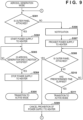
- Fig. 9 shows a control sequence in the aerosol generation mode 63.
- the control unit 120 first confirms, in step S301, that the outer panel 102 is attached to the power source unit 101 (the inner panel 202). If the outer panel 102 is attached to the power source unit 101, the control unit 120 starts, in step S302, to supply electric power to the heater H by the heating unit 130. Power supply to the heater H can be controlled in accordance with a predetermined control sequence (heating profile). After a preheating period in the heating profile, the inhaler 100 enters the inhalation enable state.
- step S303 the control unit 120 determines whether an aerosol generation end condition is satisfied.
- the aerosol generation end condition can be, for example, a condition that the number of times of puff after entering the inhalation enable state, which is acquired from the inhalation detection unit 124, has reached a predetermined number, a condition that a predetermined time has elapsed after transitioning to the aerosol generation mode 63, or the like. If the aerosol generation end condition is satisfied, the process advances to step S304, and the control unit 120 stops the power supply to the heater H. After that, in step S305, the control unit 120 transitions to the active mode 62.
- step S301 If it is determined in step S301 that the outer panel 102 is detached from the power source unit 101, the control unit 120 makes, in step S306, a notification by the display D and/or the vibration generation unit V, and prohibits, in step S307, power supply to the heater H as the function restriction.
- step S308 the control unit 120 may determine whether the outer panel 102 is attached to the power source unit 101. While the outer panel 102 is not attached to the power source unit 101, the determination processing in step S308 can be repeated for a predetermined time. However, if the predetermined time elapses (YES in step S310), the control unit 120 transitions to the active mode 62 in step S311. If the attachment of the outer panel 102 to the power source unit 101 is detected within the predetermined time, the control unit 120 cancels, in step S309, the prohibition of the power supply to the heater H as the function restriction. After that, the process returns to step S301.
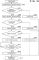
- Fig. 10 shows a control sequence in the pairing mode 66.
- the control unit 120 acquires the residual battery amount in step S401.
- the control unit 120 can acquire the residual battery amount based on the output voltage of the battery 132.
- the control unit 120 can acquire the residual battery amount based on the number of times of puff after the completion of charging, which is acquired from the inhalation detection unit 124.
- the power source unit 101 includes a management circuit that manages the battery 132
- the control unit 120 can acquire the residual battery amount based on an output from the management circuit.
- step S402 the control unit 120 determines whether the residual battery amount exceeds a predetermined threshold.
- the predetermined threshold is a threshold for determining whether to permit the operation in the pairing mode 66 with respect to the residual battery amount. More specifically, the predetermined threshold can be set as the predetermined lower limit value of the residual battery amount by assuming that electric power shortage does not occur during pairing processing. If the residual battery amount is equal to or smaller than the predetermined threshold, the power source unit 101 cannot operate in the pairing mode 66. Therefore, in step S403, the control unit 120 makes a notification by the display D and/or the vibration generation unit V, and then advances to step S413 to return to the sleep mode 61.
- step S404 the control unit 120 displays the residual battery amount on the display D.
- step S405 the control unit 120 determines whether the outer panel 102 is attached to the power source unit 101. If it is determined that the outer panel 102 is detached from the power source unit 101, the control unit 120 makes, in step S406, a notification by the display D and/or the vibration generation unit V, and advances to step S413 to return to the sleep mode 61.
- the control unit 120 prohibits execution of pairing as the function restriction. In this case, the control unit 120 leaves the pairing mode 66, and transitions to the sleep mode 61. If it is determined that the outer panel 102 is detached from the power source unit 101 in the pairing mode 66, the pairing operation performed so far may be canceled.
- step S405 If it is determined in step S405 that the outer panel 102 is attached to the power source unit 101, the control unit 120 executes, in step S407, pairing complying with Bluetooth' with an external communication device.
- step S408 the control unit 120 determines whether the pairing processing has succeeded or failed. For example, if a time-out occurs before the completion of the pairing processing, an error is notified from the external communication device, or a cancel operation of the pairing processing is detected, the control unit 120 can determine a pairing failure. Furthermore, if it is detected that the outer panel 102 is detached from the power source unit 101 during the pairing processing, the control unit 120 interrupts the pairing processing, and determines a pairing failure.
- step S408 the control unit 120 makes, in step S409, a notification that the pairing processing has succeeded, by the display D and/or the vibration generation unit V.
- step S410 the control unit 120 determines whether a pairing cancellation condition is satisfied.
- the pairing cancellation condition can be, for example, a condition that the slider 105 is operated to be set in the shutter open state, a condition that the action button B is pressed, a condition that a pairing cancellation request is received from the external communication device, a condition that a non-operation period exceeds a predetermined time, or the like. If the pairing cancellation condition is satisfied, the control unit 120 performs, in step S411, processing of disconnecting Bluetooth connection from the external communication device, and transitions to the sleep mode 61 in step S413.
- step S408 If it is determined in step S408 that the pairing processing has failed, the control unit 120 makes, in step S412, a notification that the pairing processing has failed, by the display D and/or the vibration generation unit V After that, in step S413, the control unit 120 transitions to the sleep mode 61.
- Fig. 11 shows a control sequence in the charging mode 64.
- the control unit 120 acquires the residual battery amount in step S501.
- the control unit 120 can acquire the residual battery amount based on the output voltage of the battery 132.
- the control unit 120 can acquire the residual battery amount based on the number of times of puff after the completion of charging, which is acquired from the inhalation detection unit 124.
- the power source unit 101 includes a management circuit that manages the battery 132
- the control unit 120 can acquire the residual battery amount based on an output from the management circuit.
- the control unit 120 displays the residual battery amount on the display D.
- step S503 the control unit 120 determines whether an unlock setting operation is performed.
- the unlock setting operation can be, for example, a combination of an operation of opening/closing the slider 105 and a predetermined number of times of continuous pressing of the action button B. If no unlock setting operation is detected, the control unit 120 determines in step S504 whether charging has ended. If, for example, the external power supply (charger) is detached from the connection I/F 128 or the battery 132 is set in the full charge state, it can be determined that charging has ended. If it is determined that charging has not ended, the process returns to step S501. If it is determined that charging has ended, the control unit 120 transitions to the sleep mode 61 in step S507.
- step S505 the control unit 120 determines in step S505 whether the outer panel 102 is attached to the power source unit 101. If the outer panel 102 is attached to the power source unit 101, the control unit 120 transitions to the unlock setting mode 65 in step S506. If the outer panel 102 is not attached to the power source unit 101, the control unit 120 does not transition to the unlock setting mode 65, and the process advances to step S504. That is, even if the unlock setting operation is detected in the state in which the outer panel 102 is detached, the control unit 120 does not transition to the unlock setting mode 65 as the function restriction. The unlock setting operation may be disabled. Note that if the outer panel 102 is not attached to the power source unit 101, a notification of it may be made.
- the battery 132 is continuously charged.
- transition to the unlock setting mode 65 in the state in which the outer panel 102 is detached is not permitted.
- charging processing may also not be permitted in the state in which the outer panel 102 is detached.
- Fig. 12 shows a control sequence in the unlock setting mode 65.
- the control unit 120 accepts the input of an unlock operation pattern in step S601.
- the unlock operation is an operation for transitioning from the active mode 62 to the aerosol generation mode 63.
- step S601 for example, an unlock operation pattern input within a predetermined time (for example, 20 sec) after transition to the unlock setting mode 65 is accepted.
- step S602 the control unit 120 determines whether the outer panel 102 is attached to the power source unit 101. If the outer panel 102 is attached to the power source unit 101, the control unit 120 stores, in step S603, the unlock operation pattern accepted in step S601 in the storage unit 121. After that, the control unit 120 returns to the charging mode 64 in step S605.
- step S602 If it is determined in step S602 that the outer panel 102 is not attached to the power source unit 101, the control unit 120 discards, in step S604, data of the unlock operation pattern input in step S601. After that, the control unit 120 returns to the charging mode 64 in step S605. As described above, in this embodiment, if the detachment of the outer panel 102 is detected in the unlock setting mode 65, the control unit 120 prohibits execution of setting of the unlock operation as the function restriction, and cancels the unlock operation pattern input so far.
- the control unit 120 can function as a setting unit for setting contents of the function restriction on the plurality of functions.
- a setting screen shown in Fig. 13 may be displayed on the display unit of a paired external communication device, and the user may be able to select, for each of the plurality of functions, prohibition/non-prohibition of the operation of the function in the state in which the outer panel 102 is detached.
- a hatched portion indicates a selection result by the user.
- the selection result of each function is stored in the storage unit 121.
- the control unit 120 can execute control when the outer panel 102 is detached, in accordance with the selection information stored in the storage unit 121.
- the control unit 120 is configured to impose, if the detachment of the outer panel 102 is detected, a function restriction on the plurality of functions controlled by the control unit 120. Then, the control unit 120 has the plurality of operation modes, and contents of the function restriction are different for each operation mode. This can maintain user convenience. Among others, in the state in which the outer panel 102 is detached, heating by power supply to the heater H is prohibited, and thus safety is also ensured. Therefore, according to this embodiment, there is provided an inhaler power source unit advantageous in both safety and user convenience.
Landscapes
- Engineering & Computer Science (AREA)
- Human Computer Interaction (AREA)
- Infusion, Injection, And Reservoir Apparatuses (AREA)
- Charge And Discharge Circuits For Batteries Or The Like (AREA)
Applications Claiming Priority (2)
| Application Number | Priority Date | Filing Date | Title |
|---|---|---|---|
| JP2021076014 | 2021-04-28 | ||
| PCT/JP2022/012249 WO2022230430A1 (fr) | 2021-04-28 | 2022-03-17 | Unité source d'alimentation d'inhalateur |
Publications (2)
| Publication Number | Publication Date |
|---|---|
| EP4331404A1 true EP4331404A1 (fr) | 2024-03-06 |
| EP4331404A4 EP4331404A4 (fr) | 2025-05-14 |
Family
ID=83847407
Family Applications (1)
| Application Number | Title | Priority Date | Filing Date |
|---|---|---|---|
| EP22795352.8A Pending EP4331404A4 (fr) | 2021-04-28 | 2022-03-17 | Unité source d'alimentation d'inhalateur |
Country Status (5)
| Country | Link |
|---|---|
| US (1) | US20240041129A1 (fr) |
| EP (1) | EP4331404A4 (fr) |
| JP (2) | JP7592852B2 (fr) |
| CN (1) | CN117222335A (fr) |
| WO (1) | WO2022230430A1 (fr) |
Families Citing this family (2)
| Publication number | Priority date | Publication date | Assignee | Title |
|---|---|---|---|---|
| US12438383B2 (en) | 2022-09-19 | 2025-10-07 | Altria Client Services Llc | Charging systems for aerosol-generating devices |
| US12222792B2 (en) * | 2023-02-16 | 2025-02-11 | Dell Products L.P. | Systems and methods for optimizing battery life in information handling systems using intelligence implemented in storage systems |
Family Cites Families (11)
| Publication number | Priority date | Publication date | Assignee | Title |
|---|---|---|---|---|
| US20170303593A1 (en) * | 2016-04-25 | 2017-10-26 | Lunatech, Llc | Electronic vaporizing device with security monitoring functionality |
| TW201742555A (zh) * | 2016-05-13 | 2017-12-16 | 英美煙草(投資)有限公司 | 用以加熱可吸菸材料之裝置(二) |
| GB201717476D0 (en) | 2017-10-24 | 2017-12-06 | British American Tobacco Investments Ltd | Aerosol provision system and removable member |
| TWI803585B (zh) * | 2018-03-09 | 2023-06-01 | 瑞士商菲利浦莫里斯製品股份有限公司 | 氣溶膠產生裝置及氣溶膠產生系統 |
| GB201903308D0 (en) * | 2019-03-11 | 2019-04-24 | Nicoventures Trading Ltd | Aerosol-generating device |
| EP3711498A1 (fr) * | 2019-03-22 | 2020-09-23 | Nerudia Limited | Système de substitution du tabac |
| EP3711567A1 (fr) * | 2019-03-22 | 2020-09-23 | Nerudia Limited | Système de substitution du tabac |
| KR20220002979A (ko) | 2019-05-03 | 2022-01-07 | 제이티 인터내셔널 소시에떼 아노님 | 검출기가 있는 이동식 마개를 갖는 에어로졸 발생 장치 |
| JP2021076014A (ja) | 2019-11-05 | 2021-05-20 | 日立Astemo株式会社 | 高圧燃料ポンプ |
| CN110693092A (zh) * | 2019-11-15 | 2020-01-17 | 深圳市你我网络科技有限公司 | 一种电子烟 |
| JP7633266B2 (ja) * | 2020-09-17 | 2025-02-19 | 日本たばこ産業株式会社 | 吸引装置、制御方法、及びプログラム |
-
2022
- 2022-03-17 WO PCT/JP2022/012249 patent/WO2022230430A1/fr not_active Ceased
- 2022-03-17 CN CN202280031324.4A patent/CN117222335A/zh active Pending
- 2022-03-17 JP JP2023517143A patent/JP7592852B2/ja active Active
- 2022-03-17 EP EP22795352.8A patent/EP4331404A4/fr active Pending
-
2023
- 2023-10-17 US US18/488,059 patent/US20240041129A1/en active Pending
-
2024
- 2024-11-19 JP JP2024201739A patent/JP7830604B2/ja active Active
Also Published As
| Publication number | Publication date |
|---|---|
| EP4331404A4 (fr) | 2025-05-14 |
| WO2022230430A1 (fr) | 2022-11-03 |
| JP7830604B2 (ja) | 2026-03-16 |
| KR20230170945A (ko) | 2023-12-19 |
| JPWO2022230430A1 (fr) | 2022-11-03 |
| JP7592852B2 (ja) | 2024-12-02 |
| CN117222335A (zh) | 2023-12-12 |
| JP2025015775A (ja) | 2025-01-30 |
| US20240041129A1 (en) | 2024-02-08 |
Similar Documents
| Publication | Publication Date | Title |
|---|---|---|
| EP4331408A1 (fr) | Unité d'alimentation pour inhalateur | |
| JP7830604B2 (ja) | 吸引器用の電源ユニット | |
| US12593876B2 (en) | Inhalation device, method, and program | |
| US20240049803A1 (en) | Aerosol generating apparatus, control method of aerosol generating apparatus, and storage medium | |
| KR102960417B1 (ko) | 흡인기용의 전원 유닛 | |
| US20240057676A1 (en) | Aerosol generating apparatus, control method of aerosol generating apparatus, and storage medium | |
| KR20240021233A (ko) | 흡인기용 컨트롤러 | |
| US20240130435A1 (en) | Power supply unit of aerosol generation apparatus | |
| WO2024057372A1 (fr) | Couvercle et dispositif de génération d'aérosol | |
| US12543783B2 (en) | Inhalation device, method, and program | |
| US20250194697A1 (en) | Cover member and non-transitory computer readable medium | |
| US20260123676A1 (en) | Inhalation device, method, and program | |
| EA048079B1 (ru) | Устройство генерации аэрозоля, способ управления устройством генерации аэрозоля и программа | |
| EP4613134A1 (fr) | Dispositif de génération d'aérosol et programme | |
| EP4608079A1 (fr) | Appareil électronique et programme | |
| EA051686B1 (ru) | Блок питания для ингалятора | |
| WO2024053052A1 (fr) | Dispositif de génération d'aérosol et programme | |
| CN120052054A (zh) | 盖构件 |
Legal Events
| Date | Code | Title | Description |
|---|---|---|---|
| STAA | Information on the status of an ep patent application or granted ep patent |
Free format text: STATUS: THE INTERNATIONAL PUBLICATION HAS BEEN MADE |
|
| PUAI | Public reference made under article 153(3) epc to a published international application that has entered the european phase |
Free format text: ORIGINAL CODE: 0009012 |
|
| STAA | Information on the status of an ep patent application or granted ep patent |
Free format text: STATUS: REQUEST FOR EXAMINATION WAS MADE |
|
| 17P | Request for examination filed |
Effective date: 20230929 |
|
| AK | Designated contracting states |
Kind code of ref document: A1 Designated state(s): AL AT BE BG CH CY CZ DE DK EE ES FI FR GB GR HR HU IE IS IT LI LT LU LV MC MK MT NL NO PL PT RO RS SE SI SK SM TR |
|
| RAP3 | Party data changed (applicant data changed or rights of an application transferred) |
Owner name: JAPAN TOBACCO INC. |
|
| DAV | Request for validation of the european patent (deleted) | ||
| DAX | Request for extension of the european patent (deleted) | ||
| A4 | Supplementary search report drawn up and despatched |
Effective date: 20250415 |
|
| RIC1 | Information provided on ipc code assigned before grant |
Ipc: A24F 40/65 20200101ALI20250409BHEP Ipc: A24F 40/51 20200101ALI20250409BHEP Ipc: A24F 40/50 20200101ALI20250409BHEP Ipc: A24F 40/40 20200101AFI20250409BHEP |
|
| REG | Reference to a national code |
Ref country code: DE Ref legal event code: R079 Free format text: PREVIOUS MAIN CLASS: A24F0040400000 Ipc: A24F0040530000 |
|
| GRAP | Despatch of communication of intention to grant a patent |
Free format text: ORIGINAL CODE: EPIDOSNIGR1 |
|
| STAA | Information on the status of an ep patent application or granted ep patent |
Free format text: STATUS: GRANT OF PATENT IS INTENDED |
|
| RIC1 | Information provided on ipc code assigned before grant |
Ipc: A24F 40/53 20200101AFI20260302BHEP Ipc: A24F 40/20 20200101ALN20260302BHEP Ipc: A24F 40/60 20200101ALN20260302BHEP |
|
| INTG | Intention to grant announced |
Effective date: 20260316 |