EP4331447A1 - Ofen - Google Patents
Ofen Download PDFInfo
- Publication number
- EP4331447A1 EP4331447A1 EP22792741.5A EP22792741A EP4331447A1 EP 4331447 A1 EP4331447 A1 EP 4331447A1 EP 22792741 A EP22792741 A EP 22792741A EP 4331447 A1 EP4331447 A1 EP 4331447A1
- Authority
- EP
- European Patent Office
- Prior art keywords
- air inlet
- cylinder
- hole
- inner cavity
- mounting member
- Prior art date
- Legal status (The legal status is an assumption and is not a legal conclusion. Google has not performed a legal analysis and makes no representation as to the accuracy of the status listed.)
- Granted
Links
Images



Classifications
-
- A—HUMAN NECESSITIES
- A47—FURNITURE; DOMESTIC ARTICLES OR APPLIANCES; COFFEE MILLS; SPICE MILLS; SUCTION CLEANERS IN GENERAL
- A47J—KITCHEN EQUIPMENT; COFFEE MILLS; SPICE MILLS; APPARATUS FOR MAKING BEVERAGES
- A47J37/00—Baking; Roasting; Grilling; Frying
- A47J37/06—Roasters; Grills; Sandwich grills
- A47J37/07—Roasting devices for outdoor use; Barbecues
- A47J37/0704—Roasting devices for outdoor use; Barbecues with horizontal fire box
-
- A—HUMAN NECESSITIES
- A47—FURNITURE; DOMESTIC ARTICLES OR APPLIANCES; COFFEE MILLS; SPICE MILLS; SUCTION CLEANERS IN GENERAL
- A47J—KITCHEN EQUIPMENT; COFFEE MILLS; SPICE MILLS; APPARATUS FOR MAKING BEVERAGES
- A47J37/00—Baking; Roasting; Grilling; Frying
- A47J37/06—Roasters; Grills; Sandwich grills
- A47J37/0688—Broilers with vertically disposed heat sources and food supports
-
- A—HUMAN NECESSITIES
- A47—FURNITURE; DOMESTIC ARTICLES OR APPLIANCES; COFFEE MILLS; SPICE MILLS; SUCTION CLEANERS IN GENERAL
- A47J—KITCHEN EQUIPMENT; COFFEE MILLS; SPICE MILLS; APPARATUS FOR MAKING BEVERAGES
- A47J37/00—Baking; Roasting; Grilling; Frying
- A47J37/06—Roasters; Grills; Sandwich grills
- A47J37/067—Horizontally disposed broiling griddles
- A47J37/0682—Horizontally disposed broiling griddles gas-heated
-
- F—MECHANICAL ENGINEERING; LIGHTING; HEATING; WEAPONS; BLASTING
- F24—HEATING; RANGES; VENTILATING
- F24B—DOMESTIC STOVES OR RANGES FOR SOLID FUELS; IMPLEMENTS FOR USE IN CONNECTION WITH STOVES OR RANGES
- F24B1/00—Stoves or ranges
- F24B1/18—Stoves with open fires, e.g. fireplaces
- F24B1/182—Stoves with open fires, e.g. fireplaces with additional provisions for cooking
-
- F—MECHANICAL ENGINEERING; LIGHTING; HEATING; WEAPONS; BLASTING
- F24—HEATING; RANGES; VENTILATING
- F24B—DOMESTIC STOVES OR RANGES FOR SOLID FUELS; IMPLEMENTS FOR USE IN CONNECTION WITH STOVES OR RANGES
- F24B1/00—Stoves or ranges
- F24B1/20—Ranges
- F24B1/202—Ranges specially adapted for travelling
- F24B1/207—Ranges specially adapted for travelling movable
-
- F—MECHANICAL ENGINEERING; LIGHTING; HEATING; WEAPONS; BLASTING
- F24—HEATING; RANGES; VENTILATING
- F24B—DOMESTIC STOVES OR RANGES FOR SOLID FUELS; IMPLEMENTS FOR USE IN CONNECTION WITH STOVES OR RANGES
- F24B5/00—Combustion-air or flue-gas circulation in or around stoves or ranges
- F24B5/06—Combustion-air or flue-gas circulation in or around stoves or ranges in or around ranges
- F24B5/08—Combustion-air or flue-gas circulation in or around stoves or ranges in or around ranges around the baking oven
-
- A—HUMAN NECESSITIES
- A47—FURNITURE; DOMESTIC ARTICLES OR APPLIANCES; COFFEE MILLS; SPICE MILLS; SUCTION CLEANERS IN GENERAL
- A47J—KITCHEN EQUIPMENT; COFFEE MILLS; SPICE MILLS; APPARATUS FOR MAKING BEVERAGES
- A47J37/00—Baking; Roasting; Grilling; Frying
- A47J37/06—Roasters; Grills; Sandwich grills
- A47J37/07—Roasting devices for outdoor use; Barbecues
- A47J37/0786—Accessories
- A47J2037/0795—Adjustable food supports, e.g. for height adjustment
-
- F—MECHANICAL ENGINEERING; LIGHTING; HEATING; WEAPONS; BLASTING
- F24—HEATING; RANGES; VENTILATING
- F24B—DOMESTIC STOVES OR RANGES FOR SOLID FUELS; IMPLEMENTS FOR USE IN CONNECTION WITH STOVES OR RANGES
- F24B13/00—Details solely applicable to stoves or ranges burning solid fuels
- F24B13/006—Arrangements for cleaning, e.g. soot removal; Ash removal
- F24B13/008—Ash containers
-
- Y—GENERAL TAGGING OF NEW TECHNOLOGICAL DEVELOPMENTS; GENERAL TAGGING OF CROSS-SECTIONAL TECHNOLOGIES SPANNING OVER SEVERAL SECTIONS OF THE IPC; TECHNICAL SUBJECTS COVERED BY FORMER USPC CROSS-REFERENCE ART COLLECTIONS [XRACs] AND DIGESTS
- Y02—TECHNOLOGIES OR APPLICATIONS FOR MITIGATION OR ADAPTATION AGAINST CLIMATE CHANGE
- Y02A—TECHNOLOGIES FOR ADAPTATION TO CLIMATE CHANGE
- Y02A40/00—Adaptation technologies in agriculture, forestry, livestock or agroalimentary production
- Y02A40/90—Adaptation technologies in agriculture, forestry, livestock or agroalimentary production in food processing or handling, e.g. food conservation
- Y02A40/924—Adaptation technologies in agriculture, forestry, livestock or agroalimentary production in food processing or handling, e.g. food conservation using renewable energies
- Y02A40/928—Cooking stoves using biomass
Definitions
- the present application relates to the technical field of ovens, and in particular to an oven.
- ovens on the current market burn wood or granular fuel. Most ovens are cylindrical shape due to the requirement of containing fuel, and the fuel is placed at the bottom of the cylinder for burning. Due to the limited size of the cylinder and insufficient air in the cylinder, the combustion of the fuel in the oven is insufficient, the smoke easily comes out and toxic gases are generated.
- the main purpose of the present application is to provide an oven to solve the technical problem of insufficient combustion of the fuel in the oven of the prior art.
- an oven including:
- the second air inlet channel includes an air inlet and an air outlet
- the air inlet cylinder is provided with a housing
- the air inlet is located at a bottom of the housing
- the air outlet is located on a side wall of the housing, to allow an outside air to enter from the air inlet and enter the inner cavity from the air outlet.
- the air outlet includes a third air inlet hole provided at a top of the side wall of the housing and a fourth air inlet hole provided at an end of the side wall of the housing near the bottom of the housing.
- the bottom plate is provided with an annular outer edge extending to the enclosure, the annular outer edge is provided with ventilation ports spaced circumferentially, and the ventilation ports are configured to communicate the outside air with the first air inlet channel.
- the oven further includes a charcoal basin and a baking net assembly, the top cover is provided with a fire collection hole, the charcoal basin is mounted in the fire collection hole;
- the support member is mounted with a baking net bracket
- the baking net bracket includes a first cylinder-shaped mounting member, the first cylinder-shaped mounting member is provided with a positioning hole;
- the second cylinder-shaped mounting member is further provided with penetration holes opposite to the plurality of adjustment holes, the number of penetration holes is equal to the number of adjustment holes, and the penetration holes correspond to the adjustment holes one-in-one.
- the mounting bracket is provided with a clamping groove, a size of a bottom of the clamping groove is larger than a size of an opening of the clamping groove; the mounting bracket further includes a first lapping rod and a second lapping rod, the first lapping rod is clamped to the clamping groove, the second lapping rod is provided with a concave portion, and the concave portion is abutted against the second cylinder-shaped mounting member.
- the oven further includes an ash tray, the ash tray is provided on a side of the body near the bottom plate, the ash tray includes a ventilation hole and an annular groove, the annular groove is provided directly under the first air inlet hole, and the air inlet cylinder faces the ventilation hole.
- the support member includes limiting members distributed circumferentially, and the ash tray is movable upward among the limiting members.
- the present application provides an oven, including a body assembly, an air inlet cylinder, and a support member.
- the body assembly includes a body, a top cover and an enclosure.
- the body includes a bottom plate and a side plate mounted on the bottom plate; the side plate includes a top end and a bottom end opposite to the top end; the bottom plate is provided with a first air inlet hole, a side of the side plate near the top end is provided with a second air inlet hole;
- the enclosure is provided around the side plate, the enclosure, the side plate and the top cover form a first air inlet channel, and the body is provided with an inner cavity;
- the inner cavity is communicated with the first air inlet channel through the second air inlet hole, and the inner cavity is communicated with an outside through the first air inlet hole and the first air inlet channel;
- an air inlet cylinder is provided in the inner cavity, and provided with a second air inlet channel for air entering the inner cavity from the outside; and a support member, the body assembly is mounted on
- the fuel is placed in the inner cavity for combustion and the outside air is supplied first from the first inlet hole on the bottom plate of the oven for the combustion of fuel on the bottom plate.
- the oven is heated and the outside air is heated by the side plate to move upward from the bottom of the first air inlet channel and then flows into the inner cavity through the second air inlet hole for supplying to an end of the combustion flame for the air secondary supplying to the inner cavity, to promote full combustion of insufficiently combusted fuel.
- the air inlet cylinder is heated and the air at the bottom of the air inlet cylinder is at a higher temperature, the air below the air inlet cylinder will enter the inner cavity from the second inlet channel for the air supplying to the center of the combustion flame, to promote full combustion of the fuel at the center of the combustion flame.
- the air is first supplied through the first air inlet hole, and then the air is secondary supplied to an end of the combustion flame through the first air inlet channel and the second air inlet hole, and a supplemental air is supplied to the center of the combustion flame through the second air inlet channel, to ensure the full combustion of the fuel, to increase the fire temperature and reduce the generation of smoke or toxic gases, and also provide a special flame effect.
- the present application supplies air through multiple paths to ensure sufficient air supply, such that the fuel is sufficiently combusted.
- first and second in the present application are for descriptive purposes only, and are not to be construed as indicating or implying their relative importance or implicitly specifying the number of technical features indicated.
- the features with “first” and “second” may explicitly or implicitly include at least one such feature.
- the present application provides an oven.
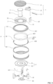
- the body assembly 4 includes a body 42, a top cover 41 and an enclosure 43.
- the body 42 includes a bottom plate 422 and a side plate 421 mounted on the bottom plate 422.
- the side plate 421 includes a top end 4211 and a bottom end 4212 opposite to the top end 4211.
- a first air inlet hole 4221 is provided on the bottom plate 422.
- a second air inlet hole is provided on a side of the side plate 421 near the top end 4211.
- the enclosure 43 is provided around the side plate 421.
- the enclosure 43, the side plate 421 and the top cover 41 form the first air inlet channel 44.
- the body 42 is provided with an inner cavity 423.
- the inner cavity 423 is configured to communicate the first air inlet channel 44 with the second air inlet hole 4213, and the inner cavity 423 is communicated with an outside through the first air inlet hole 4221 and the first air inlet channel 44.
- An air inlet cylinder 2 is provided in the inner cavity 423, and the air inlet cylinder 2 is provided with a second air inlet channel 22 for air to enter the inner cavity 423 from the outside.
- the body assembly 4 is mounted on a support member 6.
- the fuel is placed in the inner cavity 423 for combustion and the outside air is supplied first from the first inlet hole 4221 on the bottom plate 422 of the oven for the combustion of the fuel on the bottom plate 422.
- the oven is heated and the outside air is heated by the side plate 423 to move upward from the bottom of the first air inlet channel 44 and then flows into the inner cavity 423 through the second air inlet hole 4213 for supply to an end of the combustion flame for the air secondary supplying to the inner cavity 423, to promote full combustion of insufficiently combusted fuel.
- the air inlet cylinder 2 is heated and the air at the bottom of the air inlet cylinder 2 is at a higher temperature, the air below the air inlet cylinder 2 will enter the inner cavity 423 from the second inlet channel 22 for the air supplying to the center of the combustion flame, to promote full combustion of the fuel at the center of the combustion flame.
- the air is first supplied through the first air inlet hole 4221, and then the air is secondary supplied to an end of the combustion flame through the first air inlet channel 44 and the second air inlet hole 4213, and a supplemental air is supplied to the center of the combustion flame through the second air inlet channel 22, to ensure the full combustion of the fuel, to increase the fire temperature and reduce the generation of smoke or toxic gases, and also provide a special flame effect.
- wood, charcoal and granular fuel with specifications greater than 6mm can be placed in the inner cavity 423 for combustion, the inner cavity is suitable for various combustion materials, and a diameter of the first air inlet hole is less than 6mm to prevent granular fuel from falling out of the first air inlet hole.
- the support member 6 may include a plurality of support legs 61, and the support legs 61 are detachably connected to the bottom plate 422 of the body 42 for supporting the body 42 and convenient mounting and transportation.
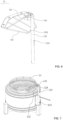
- the second air inlet channel 22 includes an air inlet 24 and an air outlet 21, and the air inlet cylinder 2 is provided with a housing 23.
- the air inlet 24 is located at a bottom of the housing 23 for communicating the outside air with the second air inlet channel 22, and the air outlet 21 is located on a side wall of the housing 23 for communicating the second air inlet channel 22 with the inner cavity 423.
- the outside air is heated in and near the air inlet 24, and the hot air rises along the second inlet channel 22 and exits from the air outlet 21 into the inner cavity 423 for a supplemental air supplying to the center of the combustion flame, to ensure full combustion of the fuel and increase the fire temperature, and also reduce the generation of smoke or toxic gases.
- the air outlet 21 includes a third air inlet hole 211 provided at a top of the side wall of the housing 23 and a fourth air inlet hole 212 provided at an end of the side wall of the housing 23 near the bottom.
- the third air inlet hole 211 is used to supplement the air for second supply to the top of the inner cavity 423 from the center of the combustion flame
- the fourth air inlet hole 212 is used to supplement the air for the first supply to the bottom of the inner cavity 423 from the center of the combustion flame.
- the bottom plate 422 is provided with an annular outer edge 4222 extending into the enclosure 43.
- the bottom plate 422 includes an inner cavity bottom 4224 and the annular outer edge 4222.
- the inner cavity bottom 4224 is located within the side plates, and the inner cavity bottom 4224 is provided with a first air inlet hole 4221.
- the annular outer edge 4222 is provided with ventilation ports 4223 spaced circumferentially for communicating the outside air with the first air inlet channel 44.
- the oven is heated and the outside air enters from the ventilation port 4223, and is heated by the side plate 421 to move upward in the first air inlet channel 44 and then flows into the inner cavity 423 from the second air inlet hole 4213 to form a secondary supplied air.
- the oven also includes a charcoal basin 3 and a baking net assembly 1.
- the top cover 41 is provided with a fire collection hole 411, and the charcoal basin 3 is mounted on the fire collection hole 411.
- the charcoal basin 3 can be placed on the fire collection hole 411 to facilitate free removal and placement of the charcoal basin 3.
- the bottom of the charcoal basin 3 is provided with a groove 31 and an ignition hole 32, the groove 31 is used to place the charcoal.
- the ignition hole 32 is used to communicate the groove 31 with the inner cavity 423. When the fuel in the inner cavity 423 is burnt, the flame ignites the charcoal in the cavity 31 through the ignition hole 32.
- the baking net assembly 1 is provided on a side of the charcoal basin 3 directly facing the groove 31, and the food is placed on the baking net assembly 1 and baked through the heat of the charcoal ignited in the groove 31.
- the support member 6 is mounted with a baking net bracket 63
- the baking net bracket 63 includes a first cylinder-shaped mounting member 631.
- the first cylinder-shaped mounting member 631 is provided with a positioning hole 6311
- the baking net assembly 1 includes a baking net 11, a mounting bracket 12 and a pin 13
- the baking net 11 is mounted on the mounting bracket 12
- the mounting bracket 12 includes a second cylinder-shaped mounting member 123.
- the second cylinder-shaped mounting member 123 is provided with a plurality of adjustment holes 1231 spaced about an axis of the second cylinder-shaped mounting member 123.
- the first cylinder-shaped mounting member 631 is sleeved on the second cylinder-shaped mounting member 123, the second cylinder-shaped mounting member 123 can move up and down in the first cylinder-shaped mounting member 631 during mounting.
- the required adjustment hole 1231 is selected to align positioning hole 6311, and then the pin 13 is inserted into the positioning hole 6311 and the selected adjustment hole 1231 to lock the first cylinder-shaped mounting member 631 and the second cylinder-shaped mounting member 123, thus to fix the baking net 11.
- Different adjustment holes 1231 are selected to lock with the positioning hole 6311, to get more baking heights to meet different baking needs.
- the second cylinder-shaped mounting member 123 also is provided with a penetration hole 1232 opposite to the adjustment hole 1231, and the number of penetration holes 1232 is equal to the number of adjustment holes 1231, and the penetration holes 1232 correspond to the adjustment holes 1231 one-in-one, so that when the baking net 11 needs to be removed from the baking area after the food is baked, etc., the pin 13 can be taken out and the baking net assembly 1 is rotated horizontally by 180°, then the pin 13 is inserted into the positioning hole 6311 and penetration hole 1232 to lock the first cylinder-shaped mounting member 631 and the second cylinder-shaped mounting member 123, the baking net 11 is rotated out over the baking area of the charcoal basin 3, to take the food conveniently for the people without being baked by the fire.
- the mounting bracket 12 is provided with a clamping groove 124, a size of a bottom of the clamping groove 124 is larger than a size of an opening of the clamping groove 124.
- the mounting bracket 12 also includes a first lapping rod 121 and a second lapping rod 122, the first lapping rod 121 is clamped to the clamping groove 124, because the size of the opening of the clamping groove 124 is larger than the size of the bottom of the clamping groove 124, the first lapping rod 122 won't slide out after being clamped.
- the second lapping rod 122 is provided with a groove 1221 to better abut against an outer circumference of the second cylinder-shaped mounting member 123.
- the baking net 11 mounted on the mounting bracket 12 is supported by the force of the first lapping rod 121 being clamped to the clamping groove 124 and the force of the second lapping rod 122 abutting against the second cylinder-shaped mounting member 123.
- the baking net 11 is flipped out of the baking area, the first lapping rod 121 is still clamped to the clamping groove 124, and the second lapping rod 122 and the second cylinder-shaped mounting member 123 are released from the clamping groove 124, so that the baking net 11 is hung to an exterior of the second cylinder-shaped mounting member 123 away from the baking area.
- the first lapping rod 121 can also be disengaged from the opening of the clamping groove 124 and removed along with the baking net 11.
- the oven also includes an ash tray 5, which is provided on a side of the body 42 near the bottom plate 422, and the ash tray 5 includes a ventilation hole 52 and an annular groove 51.
- the annular groove 51 is provided under the first air inlet hole 4221.
- the ash generated by the combustion of fuel in the inner cavity 423 falls from the first air inlet hole 4221 to the annular groove 51 to avoid the continuous accumulation of ash in the inner cavity 423 from affecting combustion or the inconvenience of cleaning due to unreasonable collection of the ash, and the air inlet cylinder 2 faces the ventilation hole 52 to avoid the ash tray 5 from blocking the outside air from entering the air inlet cylinder 2.
- the support member 6 includes limiting members 611 distributed circumferentially, the limiting members 611 can be correspondingly distributed on the support leg 61, and the ash tray 5 is movable upward among the limiting members 611, the ash tray 5 can be placed in a fixed position through the limiting members 611, to more conveniently make the annular groove 51 to face the first air inlet hole 4221 and the ventilation hole 52 to face the air inlet cylinder 2 when the ash tray 5 is placed.
- the ash tray 5 can be lifted off the limiting member 611 and removed from a side of the oven for ash cleaning.
Landscapes
- Engineering & Computer Science (AREA)
- Chemical & Material Sciences (AREA)
- Combustion & Propulsion (AREA)
- Food Science & Technology (AREA)
- Mechanical Engineering (AREA)
- General Engineering & Computer Science (AREA)
- Baking, Grill, Roasting (AREA)
Applications Claiming Priority (2)
| Application Number | Priority Date | Filing Date | Title |
|---|---|---|---|
| CN202210867640.7A CN115251728A (zh) | 2022-07-21 | 2022-07-21 | 烤炉 |
| PCT/CN2022/119130 WO2024016456A1 (zh) | 2022-07-21 | 2022-09-15 | 烤炉 |
Publications (3)
| Publication Number | Publication Date |
|---|---|
| EP4331447A1 true EP4331447A1 (de) | 2024-03-06 |
| EP4331447A4 EP4331447A4 (de) | 2025-01-22 |
| EP4331447B1 EP4331447B1 (de) | 2026-05-06 |
Family
ID=89578145
Family Applications (1)
| Application Number | Title | Priority Date | Filing Date |
|---|---|---|---|
| EP22792741.5A Active EP4331447B1 (de) | 2022-07-21 | 2022-09-15 | Ofen |
Country Status (2)
| Country | Link |
|---|---|
| US (1) | US12303069B2 (de) |
| EP (1) | EP4331447B1 (de) |
Families Citing this family (3)
| Publication number | Priority date | Publication date | Assignee | Title |
|---|---|---|---|---|
| CN220750167U (zh) * | 2023-02-24 | 2024-04-09 | 浙江永强集团股份有限公司 | 一种低烟炭炉 |
| USD1121127S1 (en) * | 2024-07-12 | 2026-03-31 | 4Patriots, Llc | Combination space heater and stove |
| US12259138B1 (en) * | 2024-08-26 | 2025-03-25 | Solo Brands, Llc | Collapsible stand for a firepit |
Family Cites Families (21)
| Publication number | Priority date | Publication date | Assignee | Title |
|---|---|---|---|---|
| US6615821B1 (en) * | 2002-08-13 | 2003-09-09 | Mark S. Stevens Industries, Inc. | Camp stove |
| US20070017500A1 (en) * | 2005-07-25 | 2007-01-25 | Shang-Chih Chen | Barbecue cooker with an adjustable split grill assembly |
| CN101554296A (zh) | 2008-04-07 | 2009-10-14 | 余文伟 | 一种便携组装式烧烤炉 |
| KR101697731B1 (ko) * | 2012-12-18 | 2017-01-18 | 정영진 | 숯불 가스를 이용한 조리기구 |
| ES2556028T3 (es) | 2012-12-19 | 2016-01-12 | Lotusgrill Gmbh | Barbacoa |
| CN203314790U (zh) | 2013-05-06 | 2013-12-04 | 何维德 | 轻便环保烤炉 |
| US20150285507A1 (en) * | 2014-04-08 | 2015-10-08 | Dan Troyer, Jr. | Reduced Smoke Outdoor Fire Burner |
| KR101671308B1 (ko) * | 2014-05-19 | 2016-11-01 | 주식회사 노나메기 | 캠핑용 난로 |
| WO2016075646A1 (en) * | 2014-11-12 | 2016-05-19 | Lello David Roydon | A gasifier stove |
| US10222092B1 (en) * | 2015-06-15 | 2019-03-05 | Original Pellet Grill Company, Llc | High-capacity sparkless mobile double-insulated wood pellet burner unit |
| EP3155938A1 (de) * | 2015-10-12 | 2017-04-19 | LotusGrill GmbH | Vorrichtung zum kochen und/oder grillen |
| CN211559772U (zh) | 2019-03-14 | 2020-09-25 | 江门宝能五金电器制造有限公司 | 一种便携式无烟烧烤炉 |
| US11378279B2 (en) * | 2019-07-17 | 2022-07-05 | Solo Brands, Llc | Combustible fuel burning stove with spark arrestor |
| US12303068B2 (en) * | 2019-08-16 | 2025-05-20 | Breeo, LLC | Outdoor fire pit and post holder |
| DE202019105975U1 (de) * | 2019-10-28 | 2020-01-16 | AVB UG (haftungsbeschränkt) | Feuerschale |
| US11457771B2 (en) * | 2020-03-11 | 2022-10-04 | Solo Brands, Llc | Packable modular combustion grill |
| US12345419B2 (en) * | 2020-12-04 | 2025-07-01 | Quality Craft Industries, Inc. | Assemblable fire pit |
| KR102363681B1 (ko) * | 2021-06-30 | 2022-02-15 | 신중배 | 기능성 캠핑용 화로 |
| US12359818B2 (en) * | 2022-02-02 | 2025-07-15 | Clifford Kenneth Young | Convertible biomass gasification stove |
| US20230397760A1 (en) * | 2022-06-09 | 2023-12-14 | Lamplight Farms Incorporated | Two piece cast iron fire pit cooktop |
| CN217959777U (zh) | 2022-07-21 | 2022-12-06 | 河源锐天科技有限公司 | 烤炉 |
-
2022
- 2022-09-15 EP EP22792741.5A patent/EP4331447B1/de active Active
- 2022-10-28 US US17/975,813 patent/US12303069B2/en active Active
Also Published As
| Publication number | Publication date |
|---|---|
| EP4331447B1 (de) | 2026-05-06 |
| US20240023754A1 (en) | 2024-01-25 |
| EP4331447A4 (de) | 2025-01-22 |
| US12303069B2 (en) | 2025-05-20 |
Similar Documents
| Publication | Publication Date | Title |
|---|---|---|
| EP4331447A1 (de) | Ofen | |
| US5553601A (en) | Barbecue | |
| US11739939B2 (en) | Self-assembly brazier for camping | |
| EP2092866A1 (de) | Grillvorrichtung | |
| KR102485585B1 (ko) | 조립식 우드 스토브 | |
| US11181278B2 (en) | Gas collapsible cooking stove | |
| CN215175237U (zh) | 柴火炉 | |
| US5143046A (en) | Solidified or semisolidified fuel barbecue grill | |
| JP2006046884A (ja) | ガスコンロ | |
| CN217959777U (zh) | 烤炉 | |
| US2646031A (en) | Utility stove | |
| US20180110366A1 (en) | Charcoal grill apparatus and method | |
| KR20100004646A (ko) | 구이기 | |
| CN209819589U (zh) | 一种可折叠炉子 | |
| TWI691678B (zh) | 具有回火現象防止結構的表面燃燒式燃燒器 | |
| WO2025071387A1 (ko) | 휴대용 숯불구이기 | |
| TW201701810A (zh) | 可攜式焙燒裝置及使用該焙燒裝置的焙燒方法 | |
| CN215112744U (zh) | 一种燃烧效率高的家用、户外火炉 | |
| WO2024016456A1 (zh) | 烤炉 | |
| CN210408157U (zh) | 一种燃气烘烤箱烘烤室 | |
| KR102696427B1 (ko) | 목재의 연소 효율을 증대시키는 구이용 화구 | |
| KR102488456B1 (ko) | 음식 조리를 위한 일회용 가열 키트 | |
| CN214678672U (zh) | 一种气、炭两用烧烤炉 | |
| JP7397374B2 (ja) | かまど装置 | |
| CN217185771U (zh) | 一种方便拆装的节能烧烤炉 |
Legal Events
| Date | Code | Title | Description |
|---|---|---|---|
| STAA | Information on the status of an ep patent application or granted ep patent |
Free format text: STATUS: UNKNOWN |
|
| STAA | Information on the status of an ep patent application or granted ep patent |
Free format text: STATUS: THE INTERNATIONAL PUBLICATION HAS BEEN MADE |
|
| PUAI | Public reference made under article 153(3) epc to a published international application that has entered the european phase |
Free format text: ORIGINAL CODE: 0009012 |
|
| STAA | Information on the status of an ep patent application or granted ep patent |
Free format text: STATUS: REQUEST FOR EXAMINATION WAS MADE |
|
| 17P | Request for examination filed |
Effective date: 20221031 |
|
| AK | Designated contracting states |
Kind code of ref document: A1 Designated state(s): AL AT BE BG CH CY CZ DE DK EE ES FI FR GB GR HR HU IE IS IT LI LT LU LV MC MK MT NL NO PL PT RO RS SE SI SK SM TR |
|
| REG | Reference to a national code |
Ref country code: DE Ref legal event code: R079 Free format text: PREVIOUS MAIN CLASS: A47J0037060000 Ipc: A47J0037070000 Ref country code: DE Ref legal event code: R079 Ref document number: 602022036432 Country of ref document: DE Free format text: PREVIOUS MAIN CLASS: A47J0037060000 Ipc: A47J0037070000 |
|
| RIC1 | Information provided on ipc code assigned before grant |
Ipc: F24B 13/00 20060101ALN20240918BHEP Ipc: F24B 5/08 20060101ALI20240918BHEP Ipc: F24B 1/182 20060101ALI20240918BHEP Ipc: F24B 1/20 20060101ALI20240918BHEP Ipc: A47J 37/07 20060101AFI20240918BHEP |
|
| A4 | Supplementary search report drawn up and despatched |
Effective date: 20241220 |
|
| RIC1 | Information provided on ipc code assigned before grant |
Ipc: F24B 13/00 20060101ALN20241216BHEP Ipc: F24B 5/08 20060101ALI20241216BHEP Ipc: F24B 1/182 20060101ALI20241216BHEP Ipc: F24B 1/20 20060101ALI20241216BHEP Ipc: A47J 37/07 20060101AFI20241216BHEP |
|
| DAX | Request for extension of the european patent (deleted) | ||
| DAV | Request for validation of the european patent (deleted) | ||
| RIC1 | Information provided on ipc code assigned before grant |
Ipc: A47J 37/07 20060101AFI20260128BHEP Ipc: F24B 1/20 20060101ALI20260128BHEP Ipc: F24B 1/182 20060101ALI20260128BHEP Ipc: F24B 5/08 20060101ALI20260128BHEP Ipc: F24B 13/00 20060101ALN20260128BHEP |
|
| GRAP | Despatch of communication of intention to grant a patent |
Free format text: ORIGINAL CODE: EPIDOSNIGR1 |
|
| STAA | Information on the status of an ep patent application or granted ep patent |
Free format text: STATUS: GRANT OF PATENT IS INTENDED |
|
| RIC1 | Information provided on ipc code assigned before grant |
Ipc: A47J 37/07 20060101AFI20260212BHEP Ipc: F24B 1/20 20060101ALI20260212BHEP Ipc: F24B 1/182 20060101ALI20260212BHEP Ipc: F24B 5/08 20060101ALI20260212BHEP Ipc: F24B 13/00 20060101ALN20260212BHEP |
|
| GRAS | Grant fee paid |
Free format text: ORIGINAL CODE: EPIDOSNIGR3 |
|
| GRAA | (expected) grant |
Free format text: ORIGINAL CODE: 0009210 |
|
| STAA | Information on the status of an ep patent application or granted ep patent |
Free format text: STATUS: THE PATENT HAS BEEN GRANTED |
|
| INTG | Intention to grant announced |
Effective date: 20260310 |