EP4331467A1 - Punktiervorrichtung - Google Patents
Punktiervorrichtung Download PDFInfo
- Publication number
- EP4331467A1 EP4331467A1 EP22795635.6A EP22795635A EP4331467A1 EP 4331467 A1 EP4331467 A1 EP 4331467A1 EP 22795635 A EP22795635 A EP 22795635A EP 4331467 A1 EP4331467 A1 EP 4331467A1
- Authority
- EP
- European Patent Office
- Prior art keywords
- distal end
- protruding
- protruding piece
- puncturing
- proximal end
- Prior art date
- Legal status (The legal status is an assumption and is not a legal conclusion. Google has not performed a legal analysis and makes no representation as to the accuracy of the status listed.)
- Withdrawn
Links
Images




Classifications
-
- A—HUMAN NECESSITIES
- A61—MEDICAL OR VETERINARY SCIENCE; HYGIENE
- A61B—DIAGNOSIS; SURGERY; IDENTIFICATION
- A61B17/00—Surgical instruments, devices or methods
- A61B17/34—Trocars; Puncturing needles
- A61B17/3478—Endoscopic needles, e.g. for infusion
-
- A—HUMAN NECESSITIES
- A61—MEDICAL OR VETERINARY SCIENCE; HYGIENE
- A61B—DIAGNOSIS; SURGERY; IDENTIFICATION
- A61B1/00—Instruments for performing medical examinations of the interior of cavities or tubes of the body by visual or photographical inspection, e.g. endoscopes; Illuminating arrangements therefor
- A61B1/00131—Accessories for endoscopes
- A61B1/00135—Oversleeves mounted on the endoscope prior to insertion
-
- A—HUMAN NECESSITIES
- A61—MEDICAL OR VETERINARY SCIENCE; HYGIENE
- A61B—DIAGNOSIS; SURGERY; IDENTIFICATION
- A61B1/00—Instruments for performing medical examinations of the interior of cavities or tubes of the body by visual or photographical inspection, e.g. endoscopes; Illuminating arrangements therefor
- A61B1/00147—Holding or positioning arrangements
- A61B1/00154—Holding or positioning arrangements using guiding arrangements for insertion
-
- A—HUMAN NECESSITIES
- A61—MEDICAL OR VETERINARY SCIENCE; HYGIENE
- A61B—DIAGNOSIS; SURGERY; IDENTIFICATION
- A61B1/00—Instruments for performing medical examinations of the interior of cavities or tubes of the body by visual or photographical inspection, e.g. endoscopes; Illuminating arrangements therefor
- A61B1/00163—Optical arrangements
- A61B1/00165—Optical arrangements with light-conductive means, e.g. fibre optics
-
- A—HUMAN NECESSITIES
- A61—MEDICAL OR VETERINARY SCIENCE; HYGIENE
- A61B—DIAGNOSIS; SURGERY; IDENTIFICATION
- A61B1/00—Instruments for performing medical examinations of the interior of cavities or tubes of the body by visual or photographical inspection, e.g. endoscopes; Illuminating arrangements therefor
- A61B1/012—Instruments for performing medical examinations of the interior of cavities or tubes of the body by visual or photographical inspection, e.g. endoscopes; Illuminating arrangements therefor characterised by internal passages or accessories therefor
- A61B1/018—Instruments for performing medical examinations of the interior of cavities or tubes of the body by visual or photographical inspection, e.g. endoscopes; Illuminating arrangements therefor characterised by internal passages or accessories therefor for receiving instruments
-
- A—HUMAN NECESSITIES
- A61—MEDICAL OR VETERINARY SCIENCE; HYGIENE
- A61B—DIAGNOSIS; SURGERY; IDENTIFICATION
- A61B1/00—Instruments for performing medical examinations of the interior of cavities or tubes of the body by visual or photographical inspection, e.g. endoscopes; Illuminating arrangements therefor
- A61B1/313—Instruments for performing medical examinations of the interior of cavities or tubes of the body by visual or photographical inspection, e.g. endoscopes; Illuminating arrangements therefor for introducing through surgical openings, e.g. laparoscopes
-
- A—HUMAN NECESSITIES
- A61—MEDICAL OR VETERINARY SCIENCE; HYGIENE
- A61B—DIAGNOSIS; SURGERY; IDENTIFICATION
- A61B1/00—Instruments for performing medical examinations of the interior of cavities or tubes of the body by visual or photographical inspection, e.g. endoscopes; Illuminating arrangements therefor
- A61B1/04—Instruments for performing medical examinations of the interior of cavities or tubes of the body by visual or photographical inspection, e.g. endoscopes; Illuminating arrangements therefor combined with photographic or television appliances
- A61B1/05—Instruments for performing medical examinations of the interior of cavities or tubes of the body by visual or photographical inspection, e.g. endoscopes; Illuminating arrangements therefor combined with photographic or television appliances characterised by the image sensor, e.g. camera, being in the distal end portion
-
- A—HUMAN NECESSITIES
- A61—MEDICAL OR VETERINARY SCIENCE; HYGIENE
- A61B—DIAGNOSIS; SURGERY; IDENTIFICATION
- A61B1/00—Instruments for performing medical examinations of the interior of cavities or tubes of the body by visual or photographical inspection, e.g. endoscopes; Illuminating arrangements therefor
- A61B1/06—Instruments for performing medical examinations of the interior of cavities or tubes of the body by visual or photographical inspection, e.g. endoscopes; Illuminating arrangements therefor with illuminating arrangements
- A61B1/0661—Endoscope light sources
- A61B1/0676—Endoscope light sources at distal tip of an endoscope
-
- A—HUMAN NECESSITIES
- A61—MEDICAL OR VETERINARY SCIENCE; HYGIENE
- A61B—DIAGNOSIS; SURGERY; IDENTIFICATION
- A61B17/00—Surgical instruments, devices or methods
- A61B17/00234—Surgical instruments, devices or methods for minimally invasive surgery
- A61B2017/00238—Type of minimally invasive operation
- A61B2017/00243—Type of minimally invasive operation cardiac
-
- A—HUMAN NECESSITIES
- A61—MEDICAL OR VETERINARY SCIENCE; HYGIENE
- A61B—DIAGNOSIS; SURGERY; IDENTIFICATION
- A61B17/00—Surgical instruments, devices or methods
- A61B17/00234—Surgical instruments, devices or methods for minimally invasive surgery
- A61B2017/00292—Surgical instruments, devices or methods for minimally invasive surgery mounted on or guided by flexible, e.g. catheter-like, means
- A61B2017/0034—Surgical instruments, devices or methods for minimally invasive surgery mounted on or guided by flexible, e.g. catheter-like, means adapted to be inserted through a working channel of an endoscope
-
- A—HUMAN NECESSITIES
- A61—MEDICAL OR VETERINARY SCIENCE; HYGIENE
- A61B—DIAGNOSIS; SURGERY; IDENTIFICATION
- A61B17/00—Surgical instruments, devices or methods
- A61B17/34—Trocars; Puncturing needles
- A61B17/3417—Details of tips or shafts, e.g. grooves, expandable, bendable; Multiple coaxial sliding cannulas, e.g. for dilating
- A61B2017/3454—Details of tips
Definitions
- the technology disclosed herein relates to a puncturing device.
- a space between two pericardial sacs surrounding a heart is called a pericardium (or pericardial cavity) and is filled with a fluid called a pericardial fluid.
- Cardiac tamponade is a highly emergent disease in which a large amount of fluid accumulates in the pericardium for some reason, increasing intrapericardial pressure, which results in insufficient expansion and dysfunction of the heart as a pump, rapidly leading to a shock state. Cardiac tamponade is treated by pericardiocentesis to drain the pericardial fluid.
- a puncturing device is used for pericardiocentesis (e.g. see Patent Literature 1) During the pericardiocentesis, the puncturing device is delivered from a patient's body surface to the pericardium in a visual field from an endoscope, and the pericardium is punctured using the puncturing device, .
- Patent Literature 1 JP 2016-158804 A
- the puncturing devices Since conventional puncturing devices have a flat distal end surface, the puncturing devices receive a high resistance from obstacles such as fat when delivered from a patient's body surface to a pericardium. When a conventional puncturing device is used, the visual field may be blocked by a forward obstacle in the advancing direction. Thus, the conventional puncturing devices have a problem that a procedure using a puncturing device cannot be efficiently executed. Such a problem is not limited to the puncturing devices for pericardiocentesis but is common to puncturing devices for puncturing a target tissue in a body.
- the technology disclosed herein can be achieved in various aspects, e.g. in an aspect such as a puncturing device, a medical device including the puncturing device, and a production method thereof.
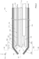
- FIG. 1 to FIG. 7 are explanatory diagrams schematically illustrating a configuration of a puncturing device 100 according to the first embodiment.
- FIG. 1 illustrates a side configuration of the puncturing device 100 with each of below-mentioned protruding pieces 42 in a maximally tapered state.
- FIG. 2 illustrates a longitudinal sectional configuration of the puncturing device 100 with each of the below-mentioned protruding pieces 42 in a maximally tapered state (sectional configuration taken along II-II in FIG. 3).
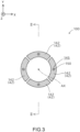
- FIG. 3 illustrates a transverse sectional configuration of the puncturing device 100 in the same state (sectional configuration taken along III-III in FIG. 2 ).
- FIG. 1 to FIG. 7 are explanatory diagrams schematically illustrating a configuration of a puncturing device 100 according to the first embodiment.
- FIG. 1 illustrates a side configuration of the puncturing device 100 with each of below-mentioned protruding pieces 42 in a maximally tapered state.
- FIG. 2 illustrates
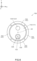
- FIG. 4 illustrates a frontal configuration of the puncturing device 100 in the same state (configuration viewed from the positive side toward the negative side in Z-axis direction).
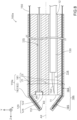
- FIG. 5 illustrates a longitudinal sectional configuration of the puncturing device 100 with each of the below-mentioned protruding pieces 42 in the straight state.
- FIG. 6 illustrates a frontal configuration of the puncturing device 100 in the same state.
- FIG. 7 illustrates a longitudinal sectional configuration of the puncturing device 100 with each of the below-mentioned protruding pieces 42 in a maximally reverse-tapered state.
- a part of the puncturing device 100 (and components thereof) is omitted.
- a positive side in Z-axis direction is a distal end side (far side) to be inserted into the body
- a negative side in Z-axis direction is a proximal end side (near side) to be manipulated by an operator such as a surgeon.
- an end on the distal end side is referred to as “distal end”
- the distal end and its vicinity are referred to as “distal end portion”
- proximal end portion an end on the proximal end side
- proximal end and its vicinity are referred to as "proximal end portion”.
- the puncturing device 100 is a medical device that is inserted into a patient's body for pericardiocentesis.
- the puncturing device 100 has a total length of about 400 mm to 600 mm and an outer diameter of about 1 mm to 5 mm.
- the distal end portion of the puncturing device 100 is a part that is inserted into a patient's body, and the proximal end portion of the puncturing device 100 is a portion that is gripped by an operator such as a surgeon.
- the puncturing device 100 includes a shaft member 110, an imaging unit 120, a puncturing needle 130, a sheath 140, operating wires 150, and a connector 160.
- the shaft member 110 is an elongated member.
- the shaft member 110 has e.g. an almost circular outer shape in a transverse section.
- the shaft member 110 is accommodated in a hollow portion 143 included in a sheath base portion 141 of the sheath 140 described later.
- the shaft member 110 is made of e.g. a resin or a metal.
- the shaft member 110 is an example of the inner portion in claims.
- a needle ejection port 11 is formed on a distal end 111 of the shaft member 110, and a needle insertion port 12 is formed on the proximal end 112 of the shaft member 110.
- a puncturing needle lumen 114 extending in the direction of central axis AX of the shaft member 110 is formed so as to communicate between the needle ejection port 11 and the needle insertion port 12.
- a transverse section of the puncturing needle lumen 114 has e.g. an almost circular outer shape.
- the puncturing needle 130 is slidably inserted into the puncturing needle lumen 114.
- the puncturing needle 130 is an elongated member having a sharp needle portion 132 on its distal end.
- the distal end portion of the puncturing needle 130 is located in the vicinity of the distal end portion of the puncturing needle lumen 114, and the proximal end portion of the puncturing needle 130 protrudes from the puncturing needle lumen 114 toward the proximal end side and is gripped by an operator.
- the connector 160 is a hollow cylindrical member attached to the proximal end portion of the sheath base portion 141 that accommodates the shaft member 110.
- the connector 160 has an opening portion 201 on its proximal end side.
- the opening portion 201 communicates with the puncturing needle lumen 114 via the needle insertion port 12 of the shaft member 110 described later.
- the operator can insert the below-mentioned puncturing needle 130 through the opening portion 201 into the puncturing needle lumen 114.
- An almost annular operating portion 200 is attached to the outside of the connector 160.
- the operating portion 200 is configured to be slidable on the outside of the connector 160 toward the proximal end side or distal end side of the sheath base portion 141.
- the operating wires 150 described later are connected to the operating portion 200.
- the operating portion 200 when the operator moves the operating portion 200 toward the proximal end side of the sheath base portion 141, the operating wires 150 are pulled toward the proximal end side, and each of the protruding pieces 42 described later shifts from the maximally tapered state to the straight state or the reverse-tapered state.
- the operating portion 200 which has been moved to the proximal end side is moved toward the distal end side of the sheath base portion 141 by the operator, a tension applied to the operating wires 150 toward the proximal end side is gradually released, and each protruding piece 42 shifts from the straight state or the reverse-tapered state to the maximally tapered state.
- the connector 160 is connected to a computer 203 via a cable 202.
- the cable 202 is electrically connected to a cable 124 that extends through an imaging unit lumen 115 described later via the connector 160. Since the cable 124 is electrically connected to the imaging unit 120 described later, the operator can control the imaging unit 120 by operating the computer 203. Since the computer 203 is also connected to a monitor 204, the operator can control the imaging unit 120 while confirming, on the monitor 204, an image captured by the imaging unit 120.
- the shaft member 110 has the imaging unit lumen 115 that extends from the distal end 111 to the proximal end 112 in the direction of the central axis AX.
- the imaging unit 120 is disposed in the imaging unit lumen 115. More specifically, the imaging unit 120 has an imaging element 122 and a cable 124.
- the imaging element 122 is an image sensor (e.g. complementary metal-oxide (CMOS) image sensor, charge-coupled device (CCD) image sensor) that generates images through imaging.
- CMOS complementary metal-oxide
- CCD charge-coupled device
- the cable 124 constitutes a transmission path for transmitting image signals generated by the imaging element 122 and extends through the imaging unit lumen 115 from the portion connected with the imaging element 122 toward the proximal end side.
- the proximal end portion of the cable 124 protrudes from the imaging unit lumen 115 toward the proximal end side and is connected, via the connector 160 and the cable 202, to the computer 203 that functionally serves as a controller for controlling the imaging unit 120.
- the imaging unit 120 may have a light source (e.g. light emitting diode (LED) and optical fiber) that emits light from the distal end of the shaft member 110 toward the distal end side.
- LED light emitting diode
- the shaft member 110 may include, in addition to the puncturing needle lumen 114 and the imaging unit lumen 115, other lumens such as a combined device lumen for inserting a combined device such as forceps, a flush lumen for flushing a fluid, and a suction lumen for sucking some tissues.
- other lumens such as a combined device lumen for inserting a combined device such as forceps, a flush lumen for flushing a fluid, and a suction lumen for sucking some tissues.
- the sheath 140 is an elongated member.
- the sheath 140 is made of e.g. a resin or a metal.
- the sheath 140 has a sheath base portion 141, a hollow sheath protruding portion 142 that protrudes from the distal end of the sheath base portion 141 toward the distal end side.
- the sheath base portion 141 is an elongated tubular portion extending along the central axis AX of the shaft member 110.
- the sheath base portion 141 has an almost annular transverse sectional shape.
- the hollow portion 143 of the sheath base portion 141 accommodates the shaft member 110.
- the sheath base portion 141 surrounds the shaft member 110.
- the position of the distal end 111 of the shaft member 110 substantially coincides with the position of the distal end (portion connected with the sheath protruding portion 142) of the sheath base portion 141.
- the sheath base portion 141 and the shaft member 110 are connected to each other so that the shaft member 110 cannot move relative to the sheath base portion 141 in the Z-axis direction.
- the shaft member 110 is connected to the proximal end portion of the sheath base portion 141.
- the connection position therebetween can be changed arbitrarily.
- the sheath base portion 141 is an example of the outer peripheral portion in claims.
- the sheath protruding portion 142 is composed of the plurality (four in the first embodiment) of protruding pieces 42 arranged around the central axis AX of the shaft member 110.
- Each protruding piece 42 is an almost trapezoidal plate-shaped piece having a proximal end 44 (portion connected with the sheath base portion 141) as a bottom side, and a distal end 43 as a top side.
- the sheath protruding portion 142 is an example of the protruding portion in the claims.
- connection portion between each protruding piece 42 and the sheath base portion 141 is more flexible than other portions of the sheath 140.
- a material and cross-sectional shape of the connection portion are made different from those of other portions.
- each protruding piece 42 is configured so as to be shiftable between a tapered state where the distal end 43 of the protruding piece 42 is closer to the central axis AX of the shaft member 110 than the proximal end 44 of the protruding piece 42 as illustrated in FIG. 1 to FIG. 4 , and a straight state where the distance from the distal end 43 of the protruding piece 42 to the central axis AX is equal to the distance from the proximal end 44 of the protruding piece 42 to the central axis AX as illustrated in FIG. 5 and FIG. 6 .
- each protruding piece 42 is also configured to be shiftable to a reverse-tapered state where the distal end 43 of the protruding piece 42 is farther from the central axis AX than the proximal end 44 of the protruding piece 42 as illustrated in FIG. 7 .
- the protruding pieces 42 are not connected to each other and therefore can be independently pivoted.
- the distal end 43 of each protruding piece 42 is closest to the central axis AX (state illustrated in FIG. 1 to FIG. 4 , hereinafter referred to as the "maximally tapered state")
- the distal end 43 of each protruding piece 42 does not reach the central axis AX, resulting in a state where an opening is ensured around the center of the sheath protruding portion 142 composed of the respective protruding pieces 42 as viewed from the front of the puncturing device 100 (see FIG. 4 ).
- each protruding piece 42 is configured to be maximally tapered in its natural state (loads excluding a weight of the protruding piece 42 itself do not act on the protruding piece 42).
- Each figure illustrates one state of each protruding piece 42 as an example, in which the inclination of each protruding piece 42 can be continuously changed from the maximally tapered state to the maximally reverse-tapered state (where the distal end 43 of each protruding piece 42 is farthest from the central axis AX as illustrated in FIG. 7 ).
- the sheath base portion 141 of the sheath 140 has a plurality (four in the first embodiment) of first wire lumens 144 that extend from the distal end (portion connected with each protruding piece 42) of the sheath base portion 141 to the proximal end.
- the protruding pieces 42 each have second wire lumens 145 that extend from the proximal end 44 of the protruding piece 42 to the distal end portion of the protruding piece 42.
- One first wire lumen 144 formed in the sheath base portion 141 communicates with the second wire lumen 145 formed in one protruding piece 42 to constitute one wire lumen 146 that extends from the proximal end of the sheath base portion 141 to the distal end portion of the sheath protruding portion 142.
- another first wire lumen 144 formed in the sheath base portion 141 communicates with the second wire lumen 145 formed in another protruding piece 42 to constitute another wire lumen 146 that extends from the proximal end of the sheath base portion 141 to the distal end portion of the sheath protruding portion 142.
- the plurality of first wire lumens 144 formed in the sheath base portion 141 correspond to the plurality of protruding pieces 42.
- Each wire lumen 146 accommodates the operating wire 150.
- the operating wire 150 is an elongated member made of e.g. a metal or a resin.
- the distal end portion 151 of the operating wire 150 is fixed to the distal end portion of the protruding piece 42, and the proximal end portion of the operating wire 150 protrudes from the proximal end of the wire lumen 146 toward the proximal end side.
- the distal end portion 151 of the operating wire 150 further extends from the distal end of the wire lumen 146 toward the distal end side and is embedded in the distal end portion of the protruding piece 42, so that the distal end portion 151 is fixed to the distal end portion of the protruding piece 42.
- Each protruding piece 42 is pivoted with the proximal end 44 of the protruding piece 42 as a fulcrum depending on a tension of the operating wires 150 caused by pulling the operating wires 150 toward the proximal end side to change the inclination of the protruding piece 42 relative to the sheath base portion 141 and shaft member 110, so that the protruding piece 42 becomes any one state from the maximally tapered state to the maximally reverse-tapered state.
- A-2. Method for Using the Puncturing Device 100 An example of a pericardiocentesis method using the puncturing device 100 will be explained below. First, the operator incises e.g. a lower part of a patient's sternum, insert the puncturing device 100 into the body through a chest hole formed by the incision, and deliver the distal end portion of the puncturing device 100 to the vicinity of the pericardium. At this time, the tension of each operating wire 150 of the puncturing device 100 is set to zero, and each protruding piece 42 is previously set to the maximally tapered state (see FIG. 1 to FIG. 4 ).
- the distal end portion of the puncturing device 100 has an almost conical shape with a diameter gradually decreasing toward the distal end side, and therefore a resistance received from obstacles such as fat can be reduced. If the puncturing device 100 receives a relatively high resistance when delivered, the operator pulls each operating wire 150 toward the proximal end side and then terminates the pulling of the operating wires 150. Thereby, the inclination of each protruding piece 42 of the puncturing device 100 is changed by pivoting the protruding piece 42 with the proximal end 44 of each protruding piece 42 as a fulcrum, so that the protruding piece shifts from the maximally tapered state to the straight state or the reverse-tapered state and then returns to the maximally tapered state.
- each protruding piece 42 As a result, obstacles are pushed aside from the front of the puncturing device 100 by the movement of each protruding piece 42, and therefore the resistance accompanying the advance of the puncturing device 100 can be effectively reduced.
- the operator pulls each operating wire 150 toward the proximal end side to shift each protruding piece 42 to the straight state. Consequently, each protruding piece 42 can be prevented from occluding the front of the imaging unit 120 to obtain a good visual field from the imaging unit 120.
- the material and shape (thickness or the like) of each protruding piece 42 are set such that the protruding piece 42 has a rigidity sufficient for pushing away obstacles such as fat.
- the operator inserts the puncturing needle 130 into the puncturing needle lumen 114 from the proximal end (needle insertion port 12) of the puncturing needle lumen 114 formed in the shaft member 110 of the puncturing device 100. Subsequently, the operator grips and advances the proximal end portion of the puncturing needle 130 so that the distal end portion of the puncturing needle 130 reaches the vicinity of the distal end (needle ejection port 11) of the puncturing needle lumen 114.
- a puncturing needle 130 may be previously inserted into the puncturing needle lumen 114 prior to the delivery. Then, the operator pulls each operating wire 150 toward the proximal end side.
- each protruding piece 42 of the puncturing device 100 shifts from the maximally tapered state to the straight state or the reverse-tapered state to obtain a good visual field from the imaging unit 120.
- the operator punctures the pericardium with the needle portion 132 of the puncturing needle 130 by advancing the puncturing needle 130 while confirming a puncture position from an image captured by the imaging unit 120.
- the pericardial sac may be pulled using forceps (not illustrated) and held in this state.
- the operator After the puncture of the pericardial sac, the operator removes the puncturing needle 130 from the puncturing needle lumen 114 to the proximal end side. Then, a syringe (not illustrated) is attached to the proximal end side of the puncturing needle lumen 114, and the pericardial fluid is sucked using the syringe to drain the pericardial fluid outside the patient's body through the proximal end of the puncturing needle lumen 114. Subsequently, the puncturing device 100 is removed from the patient's body. Thus, the pericardiocentesis using the puncturing device 100 is completed.
- the puncturing device 100 includes the shaft member 110, the sheath 140, and the imaging unit 120.
- the shaft member 110 has the puncturing needle lumen 114 that extends from the distal end 111 to the proximal end 112.
- the sheath 140 has a sheath base portion 141 and a sheath protruding portion 142.
- the sheath base portion 141 extends along the central axis AX of the shaft member 110 and surrounds the shaft member 110.
- the sheath protruding portion 142 is a hollow portion protruding from the distal end of sheath base portion 141 toward the distal end side.
- the imaging unit 120 has the imaging element 122 disposed on the distal end 111 of the shaft member 110.
- the sheath protruding portion 142 is composed of the plurality of protruding pieces 42 arranged around the central axis AX.
- Each of the plurality of protruding pieces 42 is configured to be shiftable between the tapered state where the distal end 43 of the protruding piece 42 is closer to the central axis AX than the proximal end 44 of the protruding piece 42, and the straight state where the distance from the distal end 43 of the protruding piece 42 to the central axis AX is equal to the distance from the proximal end 44 of the protruding piece 42 to the central axis AX.
- the hollow sheath protruding portion 142 that protrudes from the distal end of the sheath base portion 141 toward the distal end side is composed of the plurality of protruding pieces 42 arranged around the central axis AX, and each of the plurality of protruding pieces 42 is configured to be shiftable between the tapered state and the straight state.
- the distal end portion of the puncturing device 100 can be rendered into a shape with a diameter gradually decreasing toward the distal end side to reduce a resistance received from obstacles such as fat.
- each protruding piece 42 is shifted from the tapered state to the straight state and then returned to the tapered state, thereby obstacles can be pushed aside from the front of the puncturing device 100 by the movement of each protruding piece 42, and a resistance from the obstacles accompanying the advance of the puncturing device 100 can be effectively reduced. Furthermore, when each protruding piece 42 is shifted to the straight state, a good visual field can be obtained from the imaging unit 120. Consequently, the puncturing device 100 according to the first embodiment makes it possible to efficiently execute the procedure using the puncturing device 100.
- the sheath base portion 141 of the sheath 140 has the first wire lumens 144 that are each disposed corresponding to each of the plurality of protruding pieces 42 constituting the sheath protruding portion 142 and extend from the distal end to the proximal end of the sheath base portion 141.
- Each of the plurality of protruding pieces 42 has the second wire lumen 145 that communicates with the first wire lumen 144 on the proximal end 44 of the protruding piece 42 and extends to the distal end portion of the protruding piece 42.
- the puncturing device 100 further includes the operating wires 150 that are each accommodated in the wire lumen 146 as each combination of the first wire lumen 144 and the second wire lumen 145 communicating with each other.
- the distal end of each operating wire 150 is fixed to the distal end portion of the corresponding protruding piece 42.
- Each of the plurality of protruding pieces 42 is tapered in its natural state and is configured to be shifted from the tapered state to the straight state when the operating wire 150 is pulled toward the proximal end side.
- each of the plurality of protruding pieces 42 constituting the sheath protruding portion 142 can be shifted from the tapered state to the straight state by a simple operation of pulling each operating wire 150 toward the proximal end side, and therefore the procedure using the puncturing device 100 can be executed more efficiently.
- the shaft member 110 having the puncturing needle lumen 114 and the sheath 140 (sheath base portion 141) surrounding the shaft member 110 are constructed as separate members, and therefore it is possible to improve the design flexibility including the selection of materials for each portion of the puncturing device 100.
- FIG. 8 is an explanatory diagram schematically illustrating a configuration of a puncturing device 100a according to the second embodiment.
- components of the puncturing device 100a according to the second embodiment that are identical to the above-described components of the puncturing device 100 according to the first embodiment are provided with the same reference signs as in the first embodiment, thereby omitting the description thereof as appropriate.
- the shaft member 110 and the sheath 140 according to the first embodiment are constructed as an integral member (shaft member 110a).
- the shaft member 110a has a shaft base portion 181 and a shaft protruding portion 182.
- the shaft base portion 181 has a shaft inner portion 21 that is a part close to the central axis AX, and a shaft outer peripheral portion 22 surrounding the shaft inner portion 21.
- the shaft inner portion 21 has the puncturing needle lumen 114, and the imaging element 122 of the imaging unit 120 is disposed on the distal end of the shaft inner portion 21.
- the shaft protruding portion 182 protrudes from the distal end of the shaft outer peripheral portion 22 of the shaft base portion 181 toward the distal end side.
- the shaft protruding portion 182 is composed of a plurality (four in the second embodiment) of protruding pieces 82 arranged around the central axis AX. An inclination of each protruding piece 82 relative to the shaft outer peripheral portion 22 and the shaft inner portion 21 can be changed by pivoting the protruding piece 82 with a proximal end 84 of the protruding piece 82 as a fulcrum.
- each protruding piece 82 is configured so as to be shiftable between a tapered state where a distal end 83 of the protruding piece 82 is closer to the central axis AX than the proximal end 84 of the protruding piece 82, and a straight state where a distance from the distal end 83 of the protruding piece 82 to the central axis AX is equal to a distance from the proximal end 84 of the protruding piece 82 to the central axis AX.
- each protruding piece 82 is also configured to be shiftable to a reverse-tapered state where the distal end 83 of the protruding piece 82 is farther from the central axis AX than the proximal end 84 of the protruding piece 82.
- the shaft outer peripheral portion 22 of the shaft base portion 181 has a plurality (four in the second embodiment) of first wire lumens 184, the protruding pieces 82 each have second wire lumens 185, and each first wire lumen 184 communicates with each second wire lumen 185 to constitute a plurality of wire lumens 186.
- Each wire lumen 186 accommodates the operating wire 150.
- each protruding piece 82 The inclination of each protruding piece 82 is changed by pivoting the protruding piece 82 with the proximal end 84 of the protruding piece 82 as a fulcrum depending on a tension of the operating wire 150 caused by pulling the operating wire 150 toward the proximal end side, so that the protruding piece 82 becomes any state from the maximally tapered state to the maximally reverse-tapered state.
- the shaft inner portion 21 of the shaft base portion 181 is an example of the inner portion in the claims
- the shaft outer peripheral portion 22 of the shaft base portion 181 is an example of the outer peripheral portion in the claims
- the shaft protruding portion 182 is an example of the protruding portion in the claims.
- the puncturing device 100a includes the shaft inner portion 21 that has the puncturing needle lumen 114 extending from the distal end to the proximal end, the shaft outer peripheral portion 22 that extends along the central axis AX of the shaft inner portion 21 and surrounds the shaft inner portion 21, the hollow shaft protruding portion 182 that protrudes from the distal end of the shaft outer peripheral portion 22 toward the distal end side, and the imaging unit 120 having the imaging element 122 disposed on the distal end of the shaft inner portion 21.
- the shaft protruding portion 182 is composed of the plurality of protruding pieces 82 arranged around the central axis AX.
- Each of the plurality of protruding pieces 82 is configured so as to be shiftable between the tapered state where the distal end 83 of the protruding piece 82 is closer to the central axis AX than the proximal end 84 of the protruding piece 82, and the straight state where the distance from the distal end 83 of the protruding piece 82 to the central axis AX is equal to the distance from the proximal end 84 of the protruding piece 82 to the central axis AX. Therefore, according to the puncturing device 100a according to the second embodiment, the procedure using the puncturing device 100a can be efficiently executed like the puncturing device 100 according to the first embodiment.
- the shaft outer peripheral portion 22 of the shaft base portion 181 has the first wire lumens 184 that are each disposed corresponding to each of the plurality of protruding pieces 82 and extend from the distal end to the proximal end of the shaft outer peripheral portion 22, and the plurality of protruding pieces 82 each have the second wire lumens 185 that each communicate with each first wire lumen 184 on the proximal end 84 of the protruding piece 82 and extend to the distal end portion of the protruding piece 82.
- the puncturing device 100a further includes the operating wires 150 that are each accommodated in the wire lumen 186 as each combination of the first wire lumen 184 and the second wire lumen 185 communicating with each other.
- the distal end of each operating wire 150 is fixed to the distal end portion of the corresponding protruding piece 82.
- Each of the plurality of the protruding pieces 82 is tapered in its natural state and is configured to be shifted from the tapered state to the straight state when the operating wire 150 is pulled toward the proximal end side.
- the shaft inner portion 21 having the puncturing needle lumen 114, the shaft outer peripheral portion 22 surrounding the shaft inner portion 21, and the shaft protruding portion 182 extending from the distal end of the shaft outer peripheral portion 22 to the distal end side are constructed as an integral member, and therefore it is possible to facilitate the operation of the puncturing device 100a and to execute the procedure using the puncturing device 100a more efficiently.
- the sheath protruding portion 142 (or shaft protruding portion 182, the same applies to the following) is composed of four protruding pieces 42 (or protruding pieces 82, the same applies to the following), but the sheath protruding portion 142 may be composed of two or more and three or less protruding pieces 42, or five or more protruding pieces 42.
- each protruding piece 42 is configured to be shiftable among the tapered state, the straight state, and the reverse-tapered state, but each protruding piece 42 may be configured to be shiftable between the tapered state and the straight state but unshiftable to the reverse-tapered state.
- the puncturing device may be configured such that, when each protruding piece 42 is in the maximally tapered state, the vicinity of the center of the sheath protruding portion 142 is substantially closed.
- the operating wires 150 are accommodated in the wire lumens 146, but the operating wires 150 may be accommodated in another portion (e.g. the hollow portion 143 of the shaft member 110).
- the pivoting of each protruding piece 42 with the proximal end as a fulcrum is achieved by the operating wires 150, but may be achieved by other means (e.g. a balloon disposed in the vicinity of the proximal end of each protruding piece 42).
- each protruding piece 42 is configured to be maximally tapered in its natural state (loads excluding a weight of the protruding piece 42 itself do not act on the protruding piece 42), but the puncturing device does not necessarily have such a configuration.
- each protruding piece 42 may be configured to be straight in its natural state.
- each protruding piece 42 may be made of a material that transmits at least light of a specific wavelength used for imaging so that imaging using the imaging unit 120 is possible even when each protruding piece 42 is in the tapered state.
- the method for fixing the distal end portion 151 of the operating wire 150 to the distal end portion of each protruding piece 42 another method may be adopted (e.g. a method in which the distal end portion 151 of the operating wire 150 is made to protrude from the distal end of the protruding piece 42 toward the distal end side, and the distal end portion 151 is folded to the inner peripheral side and fixed to the inner peripheral surface of the protruding piece 42).
- the methods for using the puncturing device 100 according to the above embodiments are merely examples, and the puncturing device 100 may be used by another method.
- the techniques disclosed herein can be applied not only to the puncturing device for pericardiocentesis but also to other puncturing devices for puncturing a target tissue in a body.
Landscapes
- Health & Medical Sciences (AREA)
- Life Sciences & Earth Sciences (AREA)
- Surgery (AREA)
- General Health & Medical Sciences (AREA)
- Public Health (AREA)
- Veterinary Medicine (AREA)
- Pathology (AREA)
- Nuclear Medicine, Radiotherapy & Molecular Imaging (AREA)
- Animal Behavior & Ethology (AREA)
- Engineering & Computer Science (AREA)
- Biomedical Technology (AREA)
- Heart & Thoracic Surgery (AREA)
- Medical Informatics (AREA)
- Molecular Biology (AREA)
- Physics & Mathematics (AREA)
- Optics & Photonics (AREA)
- Biophysics (AREA)
- Radiology & Medical Imaging (AREA)
- Surgical Instruments (AREA)
- Endoscopes (AREA)
Applications Claiming Priority (2)
| Application Number | Priority Date | Filing Date | Title |
|---|---|---|---|
| JP2021073757A JP7619880B2 (ja) | 2021-04-26 | 2021-04-26 | 穿刺デバイス |
| PCT/JP2022/018174 WO2022230722A1 (ja) | 2021-04-26 | 2022-04-19 | 穿刺デバイス |
Publications (2)
| Publication Number | Publication Date |
|---|---|
| EP4331467A1 true EP4331467A1 (de) | 2024-03-06 |
| EP4331467A4 EP4331467A4 (de) | 2025-04-16 |
Family
ID=83847123
Family Applications (1)
| Application Number | Title | Priority Date | Filing Date |
|---|---|---|---|
| EP22795635.6A Withdrawn EP4331467A4 (de) | 2021-04-26 | 2022-04-19 | Punktiervorrichtung |
Country Status (4)
| Country | Link |
|---|---|
| US (1) | US20240050128A1 (de) |
| EP (1) | EP4331467A4 (de) |
| JP (1) | JP7619880B2 (de) |
| WO (1) | WO2022230722A1 (de) |
Families Citing this family (1)
| Publication number | Priority date | Publication date | Assignee | Title |
|---|---|---|---|---|
| AU2022200564B2 (en) * | 2021-02-03 | 2022-11-24 | Chin Piao Chang | Endoscope assembly having a surgical instrument and endoscope system having the same |
Family Cites Families (8)
| Publication number | Priority date | Publication date | Assignee | Title |
|---|---|---|---|---|
| JP3560931B2 (ja) | 2001-04-26 | 2004-09-02 | オリンパス株式会社 | 内視鏡挿入補助具 |
| ATE440552T1 (de) * | 2005-01-20 | 2009-09-15 | Wilson Cook Medical Inc | Biopsiezange |
| US8337394B2 (en) * | 2008-10-01 | 2012-12-25 | Ethicon Endo-Surgery, Inc. | Overtube with expandable tip |
| CN107260231A (zh) | 2008-10-20 | 2017-10-20 | 脊柱诊察公司 | 用于进入和察看脊柱的牵开器套管系统 |
| US9561048B2 (en) * | 2012-02-23 | 2017-02-07 | Boston Scientific Scimed, Inc. | Expandable endoscopic hoods and related methods of use |
| JP2016158804A (ja) | 2015-02-27 | 2016-09-05 | 国立大学法人京都大学 | 心嚢膜穿刺デバイス |
| SE541805C2 (en) | 2017-12-22 | 2019-12-17 | Multi4 Ab | An endosurgical device |
| DE202018104602U1 (de) * | 2018-08-10 | 2018-08-17 | Lohmann & Rauscher Gmbh | Schutzhülse |
-
2021
- 2021-04-26 JP JP2021073757A patent/JP7619880B2/ja active Active
-
2022
- 2022-04-19 EP EP22795635.6A patent/EP4331467A4/de not_active Withdrawn
- 2022-04-19 WO PCT/JP2022/018174 patent/WO2022230722A1/ja not_active Ceased
-
2023
- 2023-10-25 US US18/383,485 patent/US20240050128A1/en active Pending
Also Published As
| Publication number | Publication date |
|---|---|
| WO2022230722A1 (ja) | 2022-11-03 |
| JP2022168371A (ja) | 2022-11-08 |
| JP7619880B2 (ja) | 2025-01-22 |
| EP4331467A4 (de) | 2025-04-16 |
| US20240050128A1 (en) | 2024-02-15 |
Similar Documents
| Publication | Publication Date | Title |
|---|---|---|
| US11478129B2 (en) | Apparatus, systems, and methods for epicardial imaging and injection | |
| US12390095B2 (en) | Imaging apparatus and systems and methods for using them | |
| JP2024020623A (ja) | 医学的状態の処置及び注射可能物質の送達のためのアクセス装置及び方法 | |
| CN106922123A (zh) | 心包进入装置 | |
| CN111936060A (zh) | 导管以及再开通导管系统 | |
| JP2018519902A (ja) | 血管内撮像カテーテルおよびその使用方法 | |
| KR102336100B1 (ko) | 복수의 처치구 병용이 가능한 의료용 토출 기구 | |
| US9820725B2 (en) | Mucous membrane lifting instrument for endoscope and endoscope treatment system | |
| US20240050128A1 (en) | Puncturing device | |
| EA027149B1 (ru) | Управляемые дефлекторы и способы их использования | |
| JP7558269B2 (ja) | 鼓膜治療装置 | |
| US9066653B2 (en) | Devices, systems, and methods for visualizing and manipulating tissue | |
| JP2016158804A (ja) | 心嚢膜穿刺デバイス | |
| KR102898636B1 (ko) | 심실중격 관통 시스템 | |
| EP4480432A2 (de) | Systeme und verfahren für ein dissektionswerkzeug | |
| KR102725676B1 (ko) | 착탈형 내시경 | |
| EP3673843B1 (de) | Perikard katheter mit kamera zur führung des schneidens durch perikard | |
| WO2015190532A1 (ja) | 緑内障インプラント留置用器具 | |
| JP2014000480A (ja) | 補助具及び内視鏡システム |
Legal Events
| Date | Code | Title | Description |
|---|---|---|---|
| STAA | Information on the status of an ep patent application or granted ep patent |
Free format text: STATUS: THE INTERNATIONAL PUBLICATION HAS BEEN MADE |
|
| PUAI | Public reference made under article 153(3) epc to a published international application that has entered the european phase |
Free format text: ORIGINAL CODE: 0009012 |
|
| STAA | Information on the status of an ep patent application or granted ep patent |
Free format text: STATUS: REQUEST FOR EXAMINATION WAS MADE |
|
| 17P | Request for examination filed |
Effective date: 20231023 |
|
| AK | Designated contracting states |
Kind code of ref document: A1 Designated state(s): AL AT BE BG CH CY CZ DE DK EE ES FI FR GB GR HR HU IE IS IT LI LT LU LV MC MK MT NL NO PL PT RO RS SE SI SK SM TR |
|
| DAV | Request for validation of the european patent (deleted) | ||
| DAX | Request for extension of the european patent (deleted) | ||
| A4 | Supplementary search report drawn up and despatched |
Effective date: 20250318 |
|
| RIC1 | Information provided on ipc code assigned before grant |
Ipc: A61B 1/313 20060101ALI20250312BHEP Ipc: A61B 17/00 20060101ALI20250312BHEP Ipc: A61B 1/05 20060101ALI20250312BHEP Ipc: A61B 1/06 20060101ALI20250312BHEP Ipc: A61B 1/018 20060101ALI20250312BHEP Ipc: A61B 17/34 20060101ALI20250312BHEP Ipc: A61B 1/00 20060101AFI20250312BHEP |
|
| STAA | Information on the status of an ep patent application or granted ep patent |
Free format text: STATUS: THE APPLICATION HAS BEEN WITHDRAWN |
|
| 18W | Application withdrawn |
Effective date: 20250417 |