EP4331486A2 - Probensammelvorrichtung, system und verfahren zur extraktion und entnahme einer probe einer flüssigkeit eines benutzers - Google Patents
Probensammelvorrichtung, system und verfahren zur extraktion und entnahme einer probe einer flüssigkeit eines benutzers Download PDFInfo
- Publication number
- EP4331486A2 EP4331486A2 EP23185987.7A EP23185987A EP4331486A2 EP 4331486 A2 EP4331486 A2 EP 4331486A2 EP 23185987 A EP23185987 A EP 23185987A EP 4331486 A2 EP4331486 A2 EP 4331486A2
- Authority
- EP
- European Patent Office
- Prior art keywords
- cap
- sample
- collection device
- user
- incision
- Prior art date
- Legal status (The legal status is an assumption and is not a legal conclusion. Google has not performed a legal analysis and makes no representation as to the accuracy of the status listed.)
- Pending
Links
Images
















Classifications
-
- A—HUMAN NECESSITIES
- A61—MEDICAL OR VETERINARY SCIENCE; HYGIENE
- A61B—DIAGNOSIS; SURGERY; IDENTIFICATION
- A61B5/00—Measuring for diagnostic purposes; Identification of persons
- A61B5/15—Devices for taking samples of blood
- A61B5/150007—Details
- A61B5/150015—Source of blood
- A61B5/150022—Source of blood for capillary blood or interstitial fluid
-
- A—HUMAN NECESSITIES
- A61—MEDICAL OR VETERINARY SCIENCE; HYGIENE
- A61B—DIAGNOSIS; SURGERY; IDENTIFICATION
- A61B5/00—Measuring for diagnostic purposes; Identification of persons
- A61B5/15—Devices for taking samples of blood
- A61B5/150007—Details
- A61B5/150053—Details for enhanced collection of blood or interstitial fluid at the sample site, e.g. by applying compression, heat, vibration, ultrasound, suction or vacuum to tissue; for reduction of pain or discomfort; Skin piercing elements, e.g. blades, needles, lancets or canulas, with adjustable piercing speed
- A61B5/150061—Means for enhancing collection
- A61B5/150068—Means for enhancing collection by tissue compression, e.g. with specially designed surface of device contacting the skin area to be pierced
-
- A—HUMAN NECESSITIES
- A61—MEDICAL OR VETERINARY SCIENCE; HYGIENE
- A61B—DIAGNOSIS; SURGERY; IDENTIFICATION
- A61B5/00—Measuring for diagnostic purposes; Identification of persons
- A61B5/15—Devices for taking samples of blood
- A61B5/150007—Details
- A61B5/150206—Construction or design features not otherwise provided for; manufacturing or production; packages; sterilisation of piercing element, piercing device or sampling device
- A61B5/150305—Packages specially adapted for piercing devices or blood sampling devices
-
- A—HUMAN NECESSITIES
- A61—MEDICAL OR VETERINARY SCIENCE; HYGIENE
- A61B—DIAGNOSIS; SURGERY; IDENTIFICATION
- A61B5/00—Measuring for diagnostic purposes; Identification of persons
- A61B5/15—Devices for taking samples of blood
- A61B5/150007—Details
- A61B5/150206—Construction or design features not otherwise provided for; manufacturing or production; packages; sterilisation of piercing element, piercing device or sampling device
- A61B5/150312—Sterilisation of piercing elements, piercing devices or sampling devices
-
- A—HUMAN NECESSITIES
- A61—MEDICAL OR VETERINARY SCIENCE; HYGIENE
- A61B—DIAGNOSIS; SURGERY; IDENTIFICATION
- A61B5/00—Measuring for diagnostic purposes; Identification of persons
- A61B5/15—Devices for taking samples of blood
- A61B5/150007—Details
- A61B5/150351—Caps, stoppers or lids for sealing or closing a blood collection vessel or container, e.g. a test-tube or syringe barrel
-
- A—HUMAN NECESSITIES
- A61—MEDICAL OR VETERINARY SCIENCE; HYGIENE
- A61B—DIAGNOSIS; SURGERY; IDENTIFICATION
- A61B5/00—Measuring for diagnostic purposes; Identification of persons
- A61B5/15—Devices for taking samples of blood
- A61B5/150007—Details
- A61B5/150847—Communication to or from blood sampling device
-
- A—HUMAN NECESSITIES
- A61—MEDICAL OR VETERINARY SCIENCE; HYGIENE
- A61B—DIAGNOSIS; SURGERY; IDENTIFICATION
- A61B5/00—Measuring for diagnostic purposes; Identification of persons
- A61B5/15—Devices for taking samples of blood
- A61B5/151—Devices specially adapted for taking samples of capillary blood, e.g. by lancets, needles or blades
- A61B5/15101—Details
- A61B5/15103—Piercing procedure
- A61B5/15107—Piercing being assisted by a triggering mechanism
- A61B5/15113—Manually triggered, i.e. the triggering requires a deliberate action by the user such as pressing a drive button
-
- A—HUMAN NECESSITIES
- A61—MEDICAL OR VETERINARY SCIENCE; HYGIENE
- A61B—DIAGNOSIS; SURGERY; IDENTIFICATION
- A61B5/00—Measuring for diagnostic purposes; Identification of persons
- A61B5/15—Devices for taking samples of blood
- A61B5/151—Devices specially adapted for taking samples of capillary blood, e.g. by lancets, needles or blades
- A61B5/15142—Devices intended for single use, i.e. disposable
-
- A—HUMAN NECESSITIES
- A61—MEDICAL OR VETERINARY SCIENCE; HYGIENE
- A61B—DIAGNOSIS; SURGERY; IDENTIFICATION
- A61B5/00—Measuring for diagnostic purposes; Identification of persons
- A61B5/15—Devices for taking samples of blood
- A61B5/151—Devices specially adapted for taking samples of capillary blood, e.g. by lancets, needles or blades
- A61B5/15142—Devices intended for single use, i.e. disposable
- A61B5/15144—Devices intended for single use, i.e. disposable comprising driving means, e.g. a spring, for retracting the piercing unit into the housing
-
- A—HUMAN NECESSITIES
- A61—MEDICAL OR VETERINARY SCIENCE; HYGIENE
- A61B—DIAGNOSIS; SURGERY; IDENTIFICATION
- A61B5/00—Measuring for diagnostic purposes; Identification of persons
- A61B5/15—Devices for taking samples of blood
- A61B5/150007—Details
- A61B5/150053—Details for enhanced collection of blood or interstitial fluid at the sample site, e.g. by applying compression, heat, vibration, ultrasound, suction or vacuum to tissue; for reduction of pain or discomfort; Skin piercing elements, e.g. blades, needles, lancets or canulas, with adjustable piercing speed
- A61B5/150061—Means for enhancing collection
- A61B5/150099—Means for enhancing collection by negative pressure, other than vacuum extraction into a syringe by pulling on the piston rod or into pre-evacuated tubes
-
- A—HUMAN NECESSITIES
- A61—MEDICAL OR VETERINARY SCIENCE; HYGIENE
- A61B—DIAGNOSIS; SURGERY; IDENTIFICATION
- A61B5/00—Measuring for diagnostic purposes; Identification of persons
- A61B5/15—Devices for taking samples of blood
- A61B5/150007—Details
- A61B5/150343—Collection vessels for collecting blood samples from the skin surface, e.g. test tubes, cuvettes
-
- A—HUMAN NECESSITIES
- A61—MEDICAL OR VETERINARY SCIENCE; HYGIENE
- A61B—DIAGNOSIS; SURGERY; IDENTIFICATION
- A61B5/00—Measuring for diagnostic purposes; Identification of persons
- A61B5/15—Devices for taking samples of blood
- A61B5/150007—Details
- A61B5/150374—Details of piercing elements or protective means for preventing accidental injuries by such piercing elements
- A61B5/150381—Design of piercing elements
- A61B5/150442—Blade-like piercing elements, e.g. blades, cutters, knives, for cutting the skin
-
- A—HUMAN NECESSITIES
- A61—MEDICAL OR VETERINARY SCIENCE; HYGIENE
- A61B—DIAGNOSIS; SURGERY; IDENTIFICATION
- A61B5/00—Measuring for diagnostic purposes; Identification of persons
- A61B5/15—Devices for taking samples of blood
- A61B5/151—Devices specially adapted for taking samples of capillary blood, e.g. by lancets, needles or blades
- A61B5/15101—Details
- A61B5/15115—Driving means for propelling the piercing element to pierce the skin, e.g. comprising mechanisms based on shape memory alloys, magnetism, solenoids, piezoelectric effect, biased elements, resilient elements, vacuum or compressed fluids
- A61B5/15117—Driving means for propelling the piercing element to pierce the skin, e.g. comprising mechanisms based on shape memory alloys, magnetism, solenoids, piezoelectric effect, biased elements, resilient elements, vacuum or compressed fluids comprising biased elements, resilient elements or a spring, e.g. a helical spring, leaf spring, or elastic strap
-
- A—HUMAN NECESSITIES
- A61—MEDICAL OR VETERINARY SCIENCE; HYGIENE
- A61B—DIAGNOSIS; SURGERY; IDENTIFICATION
- A61B5/00—Measuring for diagnostic purposes; Identification of persons
- A61B5/15—Devices for taking samples of blood
- A61B5/151—Devices specially adapted for taking samples of capillary blood, e.g. by lancets, needles or blades
- A61B5/15101—Details
- A61B5/15126—Means for controlling the lancing movement, e.g. 2D- or 3D-shaped elements, tooth-shaped elements or sliding guides
- A61B5/15128—Means for controlling the lancing movement, e.g. 2D- or 3D-shaped elements, tooth-shaped elements or sliding guides comprising 2D- or 3D-shaped elements, e.g. cams, curved guide rails or threads
-
- A—HUMAN NECESSITIES
- A61—MEDICAL OR VETERINARY SCIENCE; HYGIENE
- A61B—DIAGNOSIS; SURGERY; IDENTIFICATION
- A61B5/00—Measuring for diagnostic purposes; Identification of persons
- A61B5/15—Devices for taking samples of blood
- A61B5/151—Devices specially adapted for taking samples of capillary blood, e.g. by lancets, needles or blades
- A61B5/15101—Details
- A61B5/15126—Means for controlling the lancing movement, e.g. 2D- or 3D-shaped elements, tooth-shaped elements or sliding guides
- A61B5/1513—Means for controlling the lancing movement, e.g. 2D- or 3D-shaped elements, tooth-shaped elements or sliding guides comprising linear sliding guides
Definitions
- the present invention concerns a sample collection device for collecting a sample of a fluid of a user, e.g. blood, in particular capillary blood.
- the present invention concerns also a system and a method for extracting and collecting this sample.
- Venepuncture is a blood collection method where the vein is punctured by a hollow needle, and where blood is collected into a tube. This method allows collection of large and high quality blood samples into tubes. Several tubes can be filled during one blood sampling. Furthermore, these tubes are compatible with highly automated blood analysers, which can analyse thousands of samples per day. These high throughputs capabilities answer the growing need to fast and clinical grade diagnostics at the lowest cost.
- this method requires a healthcare professional (e.g. a nurse) with a specific qualification and a dedicated infrastructure.
- a healthcare professional e.g. a nurse
- risks are associated with puncturing the vein: if the vein is fragile or if the gesture is not performed properly, it can result in a hematoma.
- needle-stick injury There is also a risk of needle-stick injury, which may expose the healthcare professionals to blood-borne diseases.
- the finger prick method consists in the incision of the skin at the fingertip using a lancet.
- a drop or a few drops of capillary blood can be collected into capillary tubes or into dedicated analytical devices (e.g. microfluidic devices, lab-on-chip, paper-based diagnostic tools, ). While this technique does not require highly trained professional and can be performed by the patient himself, it is very difficult to collect blood above 100 ⁇ l and to perform many analyses per sample.
- the blood collected into glass capillaries or through other devices can not be analysed by automated analysers, used by central laboratories, which require to have a minimum blood volume of 100 ⁇ l to 200 ⁇ l contained into a single tube.
- more blood up to 0.5 ml
- more blood up to 0.5 ml
- this requires to press and squeeze the finger in order to collect more blood. Squeezing too hard may result in haemolysis (damage of the red blood cells) and dilution of the blood sample by the interstitial fluid, contained in spaces between the tissue cells. For these reasons, and to keep a good blood quality, the use of finger prick is generally limited to the collection of small volumes of blood.
- the document US6283926 describes a method and a device for obtaining samples of blood for diagnostic purposes.
- the device comprises a vacuum pump, which requires a source of power, and a micro-controller arranged to drive the pump and the lancet based on the signal from a pressure sensor.
- the lancet of this device moves in a direction perpendicular to the skin of the user.
- This device is complicated, as it comprises several electronics components. Moreover, it is arranged to draw relatively small blood volumes (1 ⁇ l).
- An aim of the present invention is to propose a sample collection device which simplifies the collection of a fluid of a user, e.g. blood, while keeping a high-quality standard for its analysis.
- Another aim of the present invention is to propose a sample collection device which is safer for the user or for an operator (e.g. a nurse), as minimizes the risk of injury by handling it.
- Another aim of the present invention is to propose a sample collection device which reduces the risk of contamination of the collected sample.
- Another aim of the present invention is to propose a sample collection device which is compatible with standard blood analysers of central laboratories.
- Another aim of the present invention is to propose a system for extracting and collecting a user fluid sample which can be used without the need of high-skill training, for example which can be used by the user him-self (i.e. a patient).
- Another aim of the present invention is to propose a system for extracting and collecting a user fluid sample which requires minimal action from the user.
- Another aim of the present invention is to propose a system for extracting and collecting a user fluid sample which can collect about 0.5 ml to 2 ml of fluid, e.g.1 ml of fluid.
- Another aim of the present invention is to propose a system for extracting and collecting a user fluid sample which is as painless as possible.
- Another aim of the present invention is to propose a system for extracting and collecting a user fluid sample which avoids and/or prevents cross contamination of the fluid sample.
- these aims are achieved by means of the sample collection device, the system and the method for extracting and collecting a sample of a fluid of a user according to the attached independent claims.
- system for collecting and extracting the blood of a user comprising a blood collection device and a blood extraction device.
- the invention is not limited to such a fluid, but includes also collection devices and extraction devices, both being arranged to collect respectively extract other kinds of fluid, in particular bodily fluids.
- sample collection device and “sample extraction device”.
- sample extraction device is a sample of a fluid, in particular a bodily fluid, e.g. blood, in particular capillary blood.
- the system 300 for extracting and collecting a sample of a fluid of a user comprises two parts:
- the sample collection device 200 is consumable and the sample extraction device 100 is on the contrary reusable.
- the sample extraction device 100 is also a consumable.
- the sample collection device 200 and the sample extraction device 100 can form one single system 300 that is consumable. An example of such consumable system 300 will be discussed with reference to Fig. 36 .
- sample collection device 200 We will describe first the features of sample collection device 200, secondly the features of sample extraction device 100 and at the end the method and system of collecting and extracting such a sample.
- Fig. 1 shows a perspective view of a part of the sample collection device 200 according to one embodiment of the invention.
- the sample collection device 200 comprises:
- the sample container 212 is a tube, having substantially a cylindrical shape and comprising the open end 2121 and a closed end 2122 with a substantially spherical shape.
- the tube is a "standard" tube, i.e. a tube compatible with standard blood analysers of central laboratories.
- the diameter of the standard tube belongs to the range 12 mm - 16 mm, e.g. it is equal to 13 mm.
- the length of the tube is compatible with standard blood analysers of central laboratories. In another embodiment, the length of the tube is less than a standard length, i.e. a length compatible with standard blood analysers of central laboratories.
- the tube can comprise connexion means so as to connect it with an extension tube, so that the total length of the set comprising the tube and the extension tube is a standard length, for example a length ranging from 50 mm to 120 mm, e.g. equal to 75 mm.
- this extension tube could also correct the final diameter of the tube. The diameter of the tube could be smaller than the standard diameter, but it could be adjusted with a larger extension tube, so as to be compatible with standard blood analysers of central laboratories.
- those connection means for connecting the tube with the extension tube are arranged such that they allow an easy connection of the tube with the extension tube, but they prevent or render difficult the disconnection of the extension tube from the tube. This feature is useful in particular if a label identifying the fluid sample is placed on the outer surface of the extension tube, so as to prevent a user from detaching the extension tube from the tube: the traceability of the fluid sample is then guaranteed.
- those connection means comprise clip means and/or screwing means.
- the tube is arranged for receiving at least 0.5 ml, and preferably 1 ml, of fluid sample, as will be discussed.
- the sample container 212 is (at least partially) transparent, so as to directly see its content.
- the cap 202 is also a "standard" cap i.e. a cap compatible with standard blood analysers of central laboratories.
- the diameter of the outer part of the standard cap is 15 mm.
- the sample container 212 and its cap 202 are placed in a suction pack 201.
- the size and the shape of the suction pack 201 are therefore arranged to receive the sample container 212 and the cap 202.
- the suction pack 201 is made, at least in part, of a flexible material.
- the suction pack 201 has two main functions:
- the suction pack 201 comprises a lid 207, so as to guarantee the sterilisation of its content and/or a barrier from moisture.
- This lid 207 is removable. In one embodiment, it is a semi-permeable membrane that permits to maintain the inside of the suction pack 201 sterilized, for example Tyvek ® .
- the lid 207 is non-permeable: this allows to keep an airtight environment during storage and/or transport so as to prevent humidity from entering the suction pack 201 and/or the sample container 212. In fact, humidity could affect the stability of the additives present in the sample container 212.
- the suction pack 201 is also (at least partially) transparent, so as to give a good visual indication of the integrity of its content.
- the user or an operator, e.g. a nurse
- the lid 207 of the suction pack 201 has not been open yet, as an indication that its content is still sterilized and safe to be used.
- the suction pack 201 is made for instance of polycarbonate, PET-G, etc. so that a user or an operator can track progress of fluid collection by optically monitoring the level of the fluid sample in the sample container 212.
- the suction pack 201 comprises a semi-permeable membrane allowing the vacuum to enter in the suction pack.
- the suction pack 201 comprises or it is made (at least partially) of materials enhancing the sealing between suction pack 201 and the skin of the user, so as to guarantee a good sealing between the skin and the suction pack 201.
- the suction pack 201 is a blister pack. Consumables in blister packs is common practice in healthcare.
- the advantage of a blister packaging is that it is cost-effective, it can be closed by a removable lid 207, and can be transported and handled while preserving sterilization of its content.
- the cap 212 comprises:
- the incision mechanism is arranged to incise at the collection window 205 the user so as to exit the sample from the user.
- the cap 202 is always in a first cap position, illustrated for example in Figs. 1 , 8 , 9 and 10A .
- the cap 202 itself is arranged to be moved on the sample container 212 from a first cap position (illustrated for example in Figs. 1 , 8 , 9 or 10A ) to a second cap position (illustrated for example in Fig. 10B ), wherein in both the first and in the second cap positions the open end 2121 of the sample container 212 is at least partially in contact with the sample container 212 so as to guide the movement of the cap 202 from the first cap position to the second cap position.
- the open end 2121 of the sample container 212 is closed by the cap 202.
- the cap 202 comprises also a sealing mechanism (not illustrated), so as so seal the sample container when the cap is in the second cap position (illustrated for example in Fig. 10B ), so as to safely transport the sample.
- the movement of the incision mechanism requires no active actions from the user: in fact, it is triggered by a triggering mechanism in an automatic way, as will be described.
- the movement of the cap 202 is manually performed by the user or by an operator. However, in another embodiment, it is automatically performed as well.
- the cap 202 comprises a first cap portion 2021 and a second cap portion 2022.
- the two portions 2021, 2022 can be two distinct parts connected together by connecting means (not illustrated).
- the cap 202 is monobloc, i.e. it is made by a single piece comprising those two portions 2021, 2022.
- the first cap portion 2021 comprises the collection window 205.
- the first cap portion 2021 comprises an opening 215, along the main direction of the first cap portion 2021.
- the first cap portion 2021 has a cross section with a substantially C shape.
- At least a part 2021' of this first cap portion 2021 is inserted during all the time of the working of the system 300 in the sample container 212, so as to close the open end 2121 of the sample container 212 during the moving of the incision mechanism.
- Another part 2021" of this first cap portion 2021 is outside of the sample container 212, when the cap 202 is in its first position, as illustrated in Fig. 8 .
- the second cap portion 2022 has a size larger than the size of the first cap portion 2021. It is not adapted to enter into the sample container 212, but rather to seal it.
- the second cap portion 2022 comprises the above-mentioned sealing mechanism.
- the second cap portion 2022 comprises a cavity 216, visible in Figs. 8 and 9 , for receiving the incision mechanism, and in particular the cutting element 206, once the incision mechanism is in the second incision mechanism position (illustrated in Fig. 9 ), so that the incision mechanism is irreversibly and safely retracted in this cavity 216 so that it can no longer incise the user.
- At least a part of the cap 202 is accessible by the user or by an operator, so as to manually extract the fluid sample from the sample container 212, without detach the cap 202 from the sample container 212.
- the incision mechanism comprises:
- the support element 203 is a piston, which is for example visible in Figs. 8 and 11B ; this support element is connected, preferably directly connected, to a cutting element 206, so as once the support element 203 is moved, the cutting element 206 is moved as well.
- the cutting element 206 can be a blade, a lancet, or any other element capable of forming an opening in the skin of a user.
- the elastic element 204 is a spring, which is for example visible in Figs. 8 and 11B ; this elastic element 204 is blocked before the use of the system according to the invention, for example in a compressed position. Once the incision mechanism is triggered, the elastic element 204 is free to be decompressed, and this decompression moves the support element 203 and then the cutting element 206 from the first incision mechanism position (visible e.g. in Fig. 8 ) to the second incision mechanism position (visible e.g. in Fig. 9 ).
- the present invention is not limited to a compression elastic element only, i.e. an elastic element (e.g. a spring) that can be compressed and decompressed, but it concerns also other elastic elements, e.g. torsion and/or traction elastic elements, i.e. elastic elements (e.g. springs) that can perform a movement of torsion and/or traction.
- an elastic element e.g. a spring
- elastic elements e.g. springs
- the cutting element 206 is in the sample container 212, so as to ensure the safety of the user and/or of an operator.
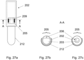
- the movement of the incision mechanism from the first incision mechanism position to the second incision mechanism position is a linear movement (i.e. a translation) performed in a direction parallel to a surface of the user to be incised, as illustrated in Fig. 27B .
- the movement of the incision mechanism from the first incision mechanism position to the second incision mechanism position is a circular movement (i.e. a rotation), as illustrated in Fig. 27C , wherein the axis of rotation of this circular movement is preferably a main axis of the sample container 212.
- this circular movement is possible if the elastic element 204 is a torsion elastic element 204. Another example of such circular movement will be discussed with reference to the embodiment of Fig. 36 .
- the triggering mechanism of the sample collection device comprises a triggering element, which is visible in for example in Figs. 11B and 11C .
- This triggering mechanism comprises a triggering element 209, which in the illustrated embodiment is a half-ring surrounding at least a part of the support element 203.
- the triggering element 209 comprises a protrusion 201, e.g. a finger, which is arranged to be received by a corresponding cavity 211 in the support element 209, so as to hold the triggering element 209 in the first triggering element position visible in for example in Fig. 11B .
- the cap 202 comprises the triggering mechanism, in particular the triggering element 209.
- the support element 203 comprises the triggering mechanism, in particular the triggering element 209.
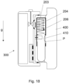
- the system 300 is on the user's skin, it is arranged to deform and/or stretch a part of the user's skin so that this deformed and/or stretched part will move the triggering element 209 from a first triggering element position (visible e.g. in Fig. 17 ), wherein it holds the elastic element 204 in a compressed position and the support element 203 in a fixed position in the sample container 212, to a second triggering element position (visible e.g. in Fig. 18 ), wherein the triggering element 209 no longer holds the elastic element 204 nor the support element 203.
- a first triggering element position visible e.g. in Fig. 17
- a second triggering element position visible e.g. in Fig. 18
- vacuum indicates an area with a gaseous pressure much less than the atmospheric pressure, e.g. with a gaseous pressure between -70 kPa and -20 kPa compared to the atmospheric pressure, e.g. of about -40 kPa.
- the valve control mechanism 102 is a button, e.g. a push button, or an assembly of buttons. In one preferred embodiment, it is arranged to control three modes of the valve 104, i.e. open, closed, release.
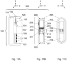
- the sample extraction device comprising an electronic module 105, visible e.g. on Fig. 11A , comprising a communication module (not illustrated) and a power supply (not illustrated).
- the sample extraction device comprises at least a sensor 106, e.g. an optic sensor, for detecting a predetermined sample volume in the sample container.
- a sensor 106 e.g. an optic sensor
- the sample extraction device comprises an alerting mechanism (not illustrated), indicating to the user the end of the sample extraction, e.g. by an audio and/or visible signal.
- the sample extraction device comprises a gasket 103, visible e.g. on Fig. 11A , cooperating with the area of the sample collection device 200 comprising a membrane 208.
- the membrane 208 is semi-permeable.
- the membrane 208 is non-permeable: this allows to keep an airtight environment during storage and/or transport so as to prevent humidity from entering the suction pack 201 and/or the sample container 212. In fact, humidity could affect the stability of the additives present in the sample container 212.
- the cap 202 is placed in and/or on the sample container 212, so as to close its open end 2121, as illustrated in Fig. 1 . Then, the sample container 212 and the cap 202 are packaged in the suction pack 202, the suction pack 202 is closed by a lid 207 and the closed suction pack 202, comprising the sample container 212 and the cap 202, is sterilized.
- the sample collection device 200 is consumable and the sample extraction device 100 is not consumable. A new sample collection device 200 is then placed on or in the sample extraction device 100, in particular in a port 107 of the sample extraction device 100, visible in Fig. 11A .
- the sample collection device 200 is then mechanically connected to the sample extraction device 100, e.g. by using first and second connection means 120 respectively 220, illustrated in Figs. 11A and 11B .
- first and second connection means 120 respectively 220 illustrated in Figs. 11A and 11B .
- Those means guarantee a connection by clipsage, but of course any other kind of means guarantying a mechanical connection between the sample collection device 200 and the sample extraction device 100 can be used, e.g. and in a non-limiting way a magnet on a device and a ferromagnetic area on the other device, a screw or a rivet in a device and a hole in the other device, docking means, etc.
- Fig. 12 shows a cross section view of one embodiment of the system for 300 extracting and collecting a sample of a fluid of a user according to the invention, before that the sample collection device 200 is inserted in the port 107 of the sample extraction device 100.
- the arrow F1 indicates the movement of the sample collection device 200 to the sample extraction device 100.
- the sample collection device 200 and the sample extraction device 100 form the system 300 according to the invention.
- Fig. 12 illustrates an embodiment in which the sample collection device 200 is moved to the extraction device 100 in the direction of the arrow F1
- this embodiment is not limitative and other possibilities can be imagined by the skilled person.
- the sample collection device 200 could be slid in some (not illustrated) rails of the extraction device 100 in a direction perpendicular to the direction of the arrow F1.
- the illustrated first and second connection means 120 respectively 220 will be modified accordingly.
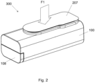
- Fig. 2 shows a perspective view of this system 300 according to one embodiment of the invention.
- the arrow F1 indicates the movement of the sample collection device 200 to the sample extraction device 100.
- sample collection device 200 and the sample extraction device 100 are arranged so that, when connected, the valve 104 and the possible gasket 103 of the sample extraction device 100 are placed in correspondence of the membrane 208 of the sample collection device 200; moreover, where present, the sensor(s) 106 of the sample extraction device 100 is(are) placed in correspondence of the sample container 212 of the sample extraction device 100.
- the system 300 according to the invention is portable. Its size allows it to be easily handled by a hand of a user.
- it is substantially a parallelepiped.
- other shapes are possible, e.g. a cylindrical shape.
- its length is in the range of 5 cm to 20 cm, e.g. 10 cm.
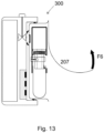
- the user removes the lid 207 of the suction pack 201, as illustrated in Figs. 3 (arrow F2) or 13 (arrow F6).
- the lid 207 guarantees the sterilisation of its content.
- a membrane 208 of the collection device 200 contributes as well to prevent cross contamination of the fluid sample.
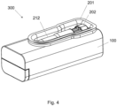
- FIG. 4 An embodiment of the system 300 without the lid 207 is illustrated in Fig. 4 .
- the suction pack 201 is (at least partially transparent) so that its content is visible.
- a vacuum creation mechanism 108 (a piston in this case, comprising a rod 109, which is moved in a direction F3 and then in the opposite direction F4) in the sample extraction device 100 so as to load vacuum into the vacuum chamber 101.
- the creation of the vacuum in the vacuum chamber 101 can be performed also before the removing of the lid 207.
- the vacuum does not need to be created by a user, e.g. by activating the vacuum creation mechanism 108, but it is already pre-packaged in the system 300 according to the invention.
- the system 300 comprises a chamber that is placed under vacuum in the manufacturing assembly line or in a healthcare facility. An example of this embodiment will be discussed with reference to Fig. 36 .
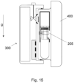
- the system 300 approaches the user 400 (as illustrated in Fig. 14 ) and it is placed on the user 400, as illustrated in Figs. 7 and 15 .
- the system 300 according to the invention is placed on the user arm, in particular an arm kept vertical, in particular with an orientation so that the cap 202 is on top and the bottom of the sample container 212 is at the bottom.
- it could be placed also on other parts of the user (e.g. legs, body, etc.), as long as this part is kept is substantially vertical (i.e. substantially parallel to the direction z of the force of gravity g) or forms a predetermined angle ⁇ with this direction z.
- the angle ⁇ formed by the direction a of the main axis of the system 300 according to the invention and the direction z of the force of gravity g is comprised in the range 0° - 45°.
- the system 300 advantageously exploits also the gravity force (in combination with the vacuum) for extracting the desired volume of the fluid sample.
- valve control mechanism 102 which in the example of Fig. 16 is a push-button which is pushed in the direction of the arrow F8.
- valve control mechanism 102 can be used instead of a push button, e.g. a rotatory button, etc.
- the valve control mechanism 102 permits to open the valve 104 so as to transfer the vacuum from the vacuum chamber 101of the sample extraction device 100 to the suction pack 201.
- this transfer is performed through an opening 218 in the suction pack 202, which is covered by a membrane 208 located in the suction pack 202.
- the membrane 208 is made of the same material of the lid 207 (e.g. Tyvek ® ).
- This membrane 208 allows also to protect the system 300 from blood contamination that could result in growth of bacteria and cross contamination between patients.
- the membrane 208 while letting air go through, prevents bodily fluids like blood permeation.
- the vacuum created into the suction pack 201 permits also to maintain the whole system 300 against the skin of the user.
- the user's part to be cut 401 is the user's part which enter into contact with the collection window 205 of the sample collection device.
- the user's part to be cut 401 as stretched and/or deformed by the vacuum transferred in the suction pack 201, actuates the triggering mechanism which in turn triggers the incision mechanism.
- the stretching and/orthe deformation of the skin in the collection window 205 i.e. the user's part to be cut 401 displaces the triggering element 209, which in the embodiment of Fig. 17 is a half-ring surrounding at least a part of the support element 23 (the piston in Fig. 17 ), so as to liberate the support element 23.
- the loaded elastic element 204 will displace the support element 203 of the incision mechanism inside the cap 202.
- the incision mechanism will be moved from a first incision mechanism position in the cap 202 (illustrated e.g. in Figs. 8 or 17 ) to a second incision mechanism position in the cap 202 (illustrated e.g. in Figs. 9 respectively 18 ).
- this cutting element 206 will section a localized part 401 of the stretched and/or deformed skin in the collection window 205.
- the incision is triggered by skin stretching and/or deformation upon applying vacuum in the suction pack 201: no user action is needed to trigger the incision.
- the system 300 ensures that the skin is sufficiently stretched and/or deformed before triggering the incision mechanism.
- the skin when stretched and/or deformed, presses against the triggering element 209 which, when pushed, displaced or deformed, releases the support element 203 onto which the cutting element 206 is connected.
- the cutting element 206 moves along the (linear or circular) trajectory of the elastic element 204 it is attached to, and incises the skin on its trajectory.
- the movement of the incision mechanism from the first incision mechanism position to the second incision mechanism position is a linear movement (i.e. a translation) performed in a direction parallel to a surface of the user to be incised.
- the incision into the skin is relatively shallow (less than 5 mm, in particular less than 3 mm into the skin, in length; the depth varies between 1 mm and 2 mm).
- the cutting element 206 makes a sharp cut into the skin.
- the incision is advantageously made while applying vacuum and/or after vacuum is applied: the skin is deformed and/or stretched and/or pinched into the sample collection device 200 before performing the incision, which reduces the feeling of the pain of the incision.
- At least a part of the edge 219 of the sample container 212 is in contact with the user 400 at a contact point or region P, at or under the incision on the user 400 made by the incision mechanism of the system 300.
- This contact point or region P guarantees that there is no space between the user 400 and the sample container 212, so that the fluid sample can fall down in the sample container 212.
- at least a part of the edge 219 is an edge of the collection window.
- the cutting element 206 is retracted into the cap 202, in particular into a cavity 216 visible in Figs. 8 and 9 , with no risk of injury or contamination to anyone handling the sample collection device 200.
- the cutting element 206 is placed at an angle ⁇ (illustrated for example in Fig. 34 ) to maximize the surface cut, without increasing the incision depth.
- the cutting element 206 can be positioned at a 90° angle with the skin, or it can be placed at a 45° angle with regard to the normal axis of the skin, maximizing the surface of the incision without increasing depth of the incision.
- the plane containing the cutting element 206 can be positioned anywhere between 45° and 90° with regard to the plane of the skin of the user.
- the length of the trajectory of the cutting element 206 allows to cut more capillaries so as to maximize the blood flow.
- the vacuum in the system 300 according to the invention has therefore three main functions:
- the frictional forces between the skin and the suction pack 201 have to be minimized. This can be done e.g. by the use of the right surface properties of the suction pack 201 and materials inside the suction pack 201 and/or the coating of the suction pack 201 and materials inside the suction pack 201 and/or coating of the skin with a silicone gel, a silicone spray or any other lubricant.
- the seal between the skin and the suction pack 201 can be enhanced and better guaranteed if no air can penetrate between the skin and the suction pack 201.
- a silicone gel, a silicone spray or any other lubricant placed between the suction pack 201 and the skin can play the role of a sealing agent.
- the materials chosen and the use of a lubricant on the suction pack 201 or on the skin will be used to enhance vacuum.
- the fluid e.g. the blood
- a sealing edge (illustrated for example in Figs. 31 and 33 , reference number 219') ensures that fluid doesn't flow out of the sample container 212, the edge of the sample container 212 being positioned near the incision 401.
- the drops of fluid 500 formed at the incision point fall into the sample container 212 by exploiting the gravity force g.
- the system 500 is designed to collect about 1 ml of fluid sample 500.
- the sample container 212 has a size similarto the tubes used for venepuncture (e.g. diameter 13 mm), making it compatible with known blood analysers.
- the blood extraction device 100 comprises at least a sensor 106, e.g. an optical sensor in correspondence of the closed end 2121 of the sample container 212, so as to detect the fluid sample volume.
- a sensor 106 e.g. an optical sensor in correspondence of the closed end 2121 of the sample container 212, so as to detect the fluid sample volume.
- the senor(s) 106 are placed in alternative or also on the sample collection device 200.
- the system 300 indicates to the user (or the operator) the end of fluid sampling, e.g. by a light, a sound or any other appropriated signals.
- valve control mechanism 102 or another valve control mechanism to put back the system 300, and in particular the suction pack 201, at atmospheric pressure.
- the user removes the system 300 from the skin of the user 400.
- the system 300 is arranged to collect a bodily fluid without the need of high-skill training. It could be used by doctors, nurses, non-trained personnel, or by the user (i.e. the patient) himself.
- the system 300 is designed to require minimal action from the user.
- the system 300 is positioned on the user, preferably on his arm kept vertical, and, pressed against the skin.
- the user only actuates the valve control mechanism 102 to trigger vacuum.
- the vacuum stretches and/or deforms the skin into the suction pack 201, maintaining it in place against the user.
- the user does not need to hold the system 300, he waits for the blood to be collected.
- the user is informed by the system 300 and then actuates again the valve control mechanism 102 to put back the system 300 to atmospheric pressure.
- the time for collecting about 1 mL of bodily fluid is in the range of 1 min to 8 min, in particular 5 min.
- the rate with which the fluid, in particular blood, exits from the user once cut by the cutting element 206 of the system 300 is in the range 4 mg/s to 11 mg/s.
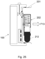
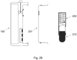
- the user moves the cap 202 onto the sample container 212 to seal it.
- the cap 202 is moved when it is still in the suction pack 201, to avoid any spillage.
- the cap 202 and the sample container 212 are taken out of the suction pack 201 and then the sample container 212 is sealed by the cap 202.
- the movement of the cap 202 from the first cap position to the second cap position is a linear movement, the cap 202 sliding onto (the outer surface of) the sample container 212 during this linear movement, as illustrated by the arrow F12 in Fig. 23 .
- the movement of the cap from the first cap position to the second cap position is in complement or in alternative a circular movement.
- the cap 202 can be screwed onto (the outer surface of) the sample container 212.
- the sealed sample container 212 can be removed from the suction pack 201 and it is ready for transport and for sample analysis.
- the suction pack 201 can then be removed from the sample extraction device 100.
- the suction pack 201 is first removed from the sample extraction device 100, and them the sample container 212 with the cap 202 are removed from the suction pack 201.
- the sample collection device 100 may be used for combining sample collection and testing.
- the sample container 212 located in the sample collection device 100 may contain one or several biomarkers pads 214 reacting with the fluid sample, allowing a direct analysis of the fluid sample by the system 300.
- the chemical reaction will produce a signal, e.g. a visible signal (light, color, etc.) which is proportional to the concentration the target to the measuring in the fluid sample (non exhaustive list: fluorescence, reflectance photometry, etc.).
- the change in color are captured by the sensor(s) 106 of the sample extraction device and converted into a concentration.
- the sample extraction device 200 in particular the sample container 212, comprises an ID element 217, e.g. a QR code, a barcode, a number, a RF tag etc.
- an ID element 217 e.g. a QR code, a barcode, a number, a RF tag etc.
- sample extraction device 200 and/or the sample extraction device 100 is (are) arranged so as to store data e.g. blood collection data (such as time of blood collection, level of blood collected, etc.), patient information, sample container barcodes, doctor's prescription data, etc....
- data e.g. blood collection data (such as time of blood collection, level of blood collected, etc.), patient information, sample container barcodes, doctor's prescription data, etc....
- sample extraction device 200 and/or the sample extraction device 100 is (are) arranged so as to communicate with external devices, in particular portable devices (e.g. smartphones, tablets, etc.) or also to cloud services to which the data can be transferred.
- portable devices e.g. smartphones, tablets, etc.
- cloud services to which the data can be transferred.
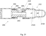
- Figs. 30 and 31 show a perspective view respectively a cross-section view of another embodiment of the sample collection device 200 according to the invention.
- the trigger element 209 is a demi-ring over the cap 202.
- the blade 206 is inclined also of an angle ⁇ with regard to the normal axis of the skin (which correspond to the normal axis of the piston 203 when the system 300 is placed on the user's skin), this angle being different from 90°. This allows the cutting element to enter more tangentially into the user's skin.
- the cap 202 is over a part of the sample container 212.
- the cap 202 does not enter into the sample container 212, but rather the sample container 212, in particular at least its end 2121, enters into the cap 202.
- the sample container 212 comprises at least two portions 2123, 2124, having different diameters d 1 respectively d 2 .
- the diameter d 1 is a standard diameter according to the definition given above.
- Figs. 30 , 31 e.g. the trigger element 209 being a demi-ring over the cap 202, the sample container 212 entering into the cap 202, the sample container 212 comprising two portions 2123, 2124, the inclined blade 206, etc.
- the trigger element 209 being a demi-ring over the cap 202
- the sample container 212 entering into the cap 202
- the sample container 212 comprising two portions 2123, 2124, the inclined blade 206, etc.
- the embodiment of Figs. 30 , 31 can be combined with any of the other previously or later described embodiments.
- Figs. 32 , 33 and 34 show a perspective view respectively cross-section views of another embodiment of the sample collection device 100 according to the invention.
- the trigger element 209 is not a demi-ring over the cap 202, as in Figs. 30 and 31 .
- the trigger element 209 is a tab 209' in the cap 202, which is held in place by the finger 210'. The skin of the user, once deformed by the vacuum, will move the tab 209' in the direction of the arrow F14, by liberating the tab 209' from the finger 210' so as to liberate the elastic element 204 and therefor the piston 203 with the cutting element 206.
- the blade 206 is inclined of an angle ⁇ with regard to the normal axis of the skin, this angle being different from 90°, as in Figs. 30 and 31 .
- the cap 202 is over a part of the sample container 212, as in Figs. 30 and 31 .
- the sample container 212 comprises two portions 2123, 2124, having different diameters d 1 respectively d 2 as in Figs. 30 and 31 .
- the features illustrated in the embodiment of Figs. 32 , 33 and 34 are not necessarily together present.
- the embodiment of Figs. 32 , 33 can be combined with any of the other previously or later described embodiments.
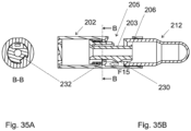
- Figs. 35A and 35B show cross-section views of another embodiment of the sample collection device 200 according to the invention.
- the support element 203 comprises a protrusion 230, which, once the support element is moved in the direction of the arrow F15 by the triggering mechanism, will enter into contact with the finger 232 of the cap 202: this will cause a mechanical movement of all the support element 203, and then of the cutting element 206, toward the user's skin, so that the cutting element will move toward the user's skin while cutting it. In such a way, a more deep cut could be realised in the user's skin.
- the shape and the size of the protrusion 230 and/or of the finger 232 are selected so that the movement of the cutting element 206 toward the user's skin is performed while the cutting element 206 is cutting the user's skin.
- Other means can be imagined in order to move the cutting element 206 toward the user's skin while it cuts the skin. This embodiment can be combined with any of the other previously or later described embodiments.
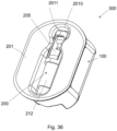
- Fig. 36 shows a perspective view of another embodiment of the system 300 for extracting and collecting a sample of a fluid of a user according to the invention.
- this embodiment :
- Fig. 37 shows an exploded view of the embodiment of the system 300 of Fig. 36 .
- the suction pack 201 present in the previously described embodiments is a first suction pack 201 (or inner suction pack 201), and the system 300 comprises a second suction pack 110 (or outer suction pack 110).
- the first suction pack 201 comprises a cavity 2010 arranged to receive the sample container 212 and the cap 202, and having a first thickness.
- the second suction pack 110 comprises a cavity 1100, having a second thickness, which is greater than the first thickness.
- the first suction pack 201 is arranged to be received by the second suction pack 110, so that the difference between the two thicknesses creates a chamber that is placed under vacuum in the manufacturing assembly line or in a healthcare facility.
- the pre-packaged vacuum is made by adding a second suction pack 110 on top of the first suction pack 201 so to create this chamber.
- the first and second suction packs are arranged so that, once the second suction pack 110 receives the first suction pack 201, they can be permanently sealed together.
- the system 300 of the embodiment of Fig. 37 comprises also means for transferring the vacuum from the chamber placed under vacuum in the manufacturing assembly line or in a healthcare facility (in the following, second vacuum chamber) to the first vacuum chamber 101, once a user wished to activate the system 300.
- the second suction pack 110 comprises a bistable element (as a button) on one of its outer surfaces.
- a bistable element as a button
- An example of such bistable element is visible in Fig. 38 , which shows a part of a cross-section view of the embodiment of the system of Figs. 36 , 37 .
- the first suction pack 201 comprises also a piercing protrusion (reference 2014 in Fig. 34 ) .
- the bistable element 2012 e.g. pressing on the second suction pack 110
- the piercing protrusion 2014 will pierce a membrane 208 placed on the first suction pack 201, thereby transferring the vacuum in the first vacuum chamber or collection chamber. This will start the collection of the liquid sample.
- this membrane is non-permeable, so as to avoid a vacuum transfer before the use of the system 300.
- the second suction pack 110 comprises also one or more holes 2010, completely covered by a removable cap 140, e.g. a rubber removable cap 140.
- a removable cap 140 e.g. a rubber removable cap 140.
- the user can remove, e.g. by pulling, the removable cap 140 so as to low the pressure in the collection chamber to the atmospheric pressure, thereby stopping the start the collection of the liquid sample.
- a (removable) label 130 can cover the back of the second suction pack 110.
- Fig. 39 shows another part of another cross-section view of the embodiment of the system of Fig. 36 .
- the cutting element 206 makes an incision in the skin of the user by moving into a rotational movement around the main central axis of the tube (and cap 202). This rotational movement allows to have a more compact triggering and incision mechanism. In fact, by choosing a rotational movement of the cutting element 206, the overall length of the triggering mechanism is reduced, allowing for a smaller dimension of the cap 202 and a smaller overall system 300.
- the cap 202 comprises on its top one or more deformable elements 2020, visible in Fig. 39 , which is(are) arranged to be deformed in the direction of the arrow F16.
- the deformable element(s) 2020 is(are) part of the triggering mechanism.
- the skin is sucked into the chamber and presses against the deformable element(s) 2020 on the cap 202.
- the deformable element(s) 2020 free the rotational piston 203 previously loaded with a (torsion) spring 204.
- Fig. 41A shows a perspective view (front side) of one embodiment of the sample collection device of the system of Fig. 36 .
- Fig. 41B shows a perspective view (rear side) of the embodiment of the sample collection device of Fig. 41A .
- the triggering element is part of the cap 202.
- the deformable elements 2020 belong to a supplementary piece, fixed (in a movable or unmovable way) to the cap 202.
- the deformable elements 2020 are larger than in previous variants, for a wider area of contact between the skin and the triggering mechanism permitting to have more reliability in the triggering mechanism.
- the cap 202 comprises a liberation notch 2021.
- the skin will press the triggering surface 2022 of the cap 202, by pushing the notch 2021 and setting the piston 203 free.
- Increasing the length of the collection window 205 allows to improve the skin stretching. Having a rotational movement of the cutting element 206 allows that the length of the incision is not dependent on the length of the collection window 205 (proportional the window's width), as it is the case with a translational movement of the cutting element 206.
- the cavity 2010 of the suction pack 201 arranged to receive the collection container 212, has a waisted shape, which is narrower at or near the collection window 205, in particular at or near the incision area, so as to allow for a better stretching of the skin.
- the applicant has noticed that the skin deforms well along the edges 2011 of the cavity 2010 of the suction pack 201.
- the edges of the cavity 2010 of the suction pack 201 are arranged closer to the incision area, by making it narrower.
- Fig. 42 shows a top view of the system 300 according to the invention, once placed near a user's member as an arm.
- the suction pack 201 in contact with the skin, has a shape and/or a curvature 2013 to fit the shape and/or the curvature of the arm 400 to ensure a better seal between the skin and the suction pack 201.
- this shape and/or this curvature can be adapted or changed by the user, so as to better fit with the user, in particular with young users.
Landscapes
- Health & Medical Sciences (AREA)
- Life Sciences & Earth Sciences (AREA)
- Engineering & Computer Science (AREA)
- Molecular Biology (AREA)
- Animal Behavior & Ethology (AREA)
- Pathology (AREA)
- Physics & Mathematics (AREA)
- Biomedical Technology (AREA)
- Heart & Thoracic Surgery (AREA)
- Medical Informatics (AREA)
- Hematology (AREA)
- Surgery (AREA)
- Biophysics (AREA)
- General Health & Medical Sciences (AREA)
- Public Health (AREA)
- Veterinary Medicine (AREA)
- Dermatology (AREA)
- Manufacturing & Machinery (AREA)
- Diabetes (AREA)
- Pain & Pain Management (AREA)
- Investigating Or Analysing Biological Materials (AREA)
- Measurement Of The Respiration, Hearing Ability, Form, And Blood Characteristics Of Living Organisms (AREA)
- Sampling And Sample Adjustment (AREA)
Applications Claiming Priority (3)
| Application Number | Priority Date | Filing Date | Title |
|---|---|---|---|
| CH5952018 | 2018-05-14 | ||
| PCT/IB2019/053986 WO2019220340A1 (en) | 2018-05-14 | 2019-05-14 | Sample collection device, system and method for extracting and collecting a sample of a fluid of a user |
| EP19735383.2A EP3793442B1 (de) | 2018-05-14 | 2019-05-14 | Probensammelvorrichtung und system zum extrahieren und sammeln einer probe einer flüssigkeit eines benutzers |
Related Parent Applications (1)
| Application Number | Title | Priority Date | Filing Date |
|---|---|---|---|
| EP19735383.2A Division EP3793442B1 (de) | 2018-05-14 | 2019-05-14 | Probensammelvorrichtung und system zum extrahieren und sammeln einer probe einer flüssigkeit eines benutzers |
Publications (2)
| Publication Number | Publication Date |
|---|---|
| EP4331486A2 true EP4331486A2 (de) | 2024-03-06 |
| EP4331486A3 EP4331486A3 (de) | 2024-04-03 |
Family
ID=63113297
Family Applications (2)
| Application Number | Title | Priority Date | Filing Date |
|---|---|---|---|
| EP23185987.7A Pending EP4331486A3 (de) | 2018-05-14 | 2019-05-14 | Probensammelvorrichtung, system und verfahren zur extraktion und entnahme einer probe einer flüssigkeit eines benutzers |
| EP19735383.2A Active EP3793442B1 (de) | 2018-05-14 | 2019-05-14 | Probensammelvorrichtung und system zum extrahieren und sammeln einer probe einer flüssigkeit eines benutzers |
Family Applications After (1)
| Application Number | Title | Priority Date | Filing Date |
|---|---|---|---|
| EP19735383.2A Active EP3793442B1 (de) | 2018-05-14 | 2019-05-14 | Probensammelvorrichtung und system zum extrahieren und sammeln einer probe einer flüssigkeit eines benutzers |
Country Status (5)
| Country | Link |
|---|---|
| US (2) | US12290361B2 (de) |
| EP (2) | EP4331486A3 (de) |
| JP (1) | JP7438137B2 (de) |
| CN (1) | CN112203586B (de) |
| WO (1) | WO2019220340A1 (de) |
Families Citing this family (13)
| Publication number | Priority date | Publication date | Assignee | Title |
|---|---|---|---|---|
| HK1258397A1 (zh) | 2015-09-09 | 2019-11-08 | Drawbridge Health, Inc. | 用於样品收集、稳定化和保存的系统、方法和装置 |
| SG10201911879UA (en) | 2017-01-10 | 2020-01-30 | Drawbridge Health Inc | Devices, systems, and methods for sample collection |
| US20230138274A1 (en) * | 2020-03-31 | 2023-05-04 | Preci Health Sa | Body Fluids Sampling Device and Method of using the Same |
| WO2022043748A2 (en) * | 2020-08-23 | 2022-03-03 | Preci Health Sa | Capillary blood sampling device and method of use |
| EP4000518A1 (de) * | 2020-11-24 | 2022-05-25 | Loop Medical SA | Auslösemechanismus für eine probensammelvorrichtung und probensammelvorrichtung damit |
| EP4000730B1 (de) * | 2020-11-24 | 2023-01-04 | Loop Medical SA | Probenentnahmevorrichtung |
| EP4066738B1 (de) | 2021-03-29 | 2024-10-23 | Loop Medical SA | Elektronisches modul für eine probensammelvorrichtung und system damit |
| WO2023067389A1 (en) * | 2021-10-20 | 2023-04-27 | Paulus Holdings Limited | Devices for collecting capillary blood and methods for same |
| US11478175B1 (en) | 2021-10-20 | 2022-10-25 | Paulus Holdings Limited | Devices for collecting capillary blood and methods for same |
| US11957465B2 (en) | 2022-08-23 | 2024-04-16 | Reddrop Dx, Inc. | Accelerated ergonomic collection of capillary blood |
| JPWO2024042932A1 (de) * | 2022-08-24 | 2024-02-29 | ||
| WO2026064426A1 (en) * | 2024-09-17 | 2026-03-26 | Tasso, Inc. | Methods and systems for collecting bodily fluid |
| US20260174364A1 (en) * | 2024-12-20 | 2026-06-25 | Remidio Innovative Solutions Private Limited | Blood extraction device |
Citations (1)
| Publication number | Priority date | Publication date | Assignee | Title |
|---|---|---|---|---|
| US6283926B1 (en) | 1996-12-06 | 2001-09-04 | Abbott Laboratories | Method and apparatus for obtaining blood for diagnostic tests |
Family Cites Families (29)
| Publication number | Priority date | Publication date | Assignee | Title |
|---|---|---|---|---|
| US5662127A (en) | 1996-01-17 | 1997-09-02 | Bio-Plas, Inc. | Self-contained blood withdrawal apparatus and method |
| US20020087180A1 (en) * | 2000-12-29 | 2002-07-04 | Searle Stephen D. | Blood lancet |
| EP1687620B1 (de) * | 2003-11-14 | 2014-04-23 | Alere Switzerland GmbH | Probensammelgefäss mit integriertem probenanalysesystem |
| US10227063B2 (en) | 2004-02-26 | 2019-03-12 | Geelux Holdings, Ltd. | Method and apparatus for biological evaluation |
| JP2009542304A (ja) | 2006-07-06 | 2009-12-03 | ラピッディックス エルティーディー. | 統合型採血及び試験器具及びその使用方法 |
| US9186097B2 (en) * | 2007-09-17 | 2015-11-17 | Roche Diabetes Care, Inc. | Body fluid lancing, acquiring, and testing cartridge design |
| CN201379576Y (zh) | 2009-04-17 | 2010-01-13 | 张立波 | 一次性采血针 |
| CN201505140U (zh) * | 2009-10-27 | 2010-06-16 | 天津华鸿医材有限公司 | 一种针刺深度可调式采血笔 |
| ES2565805T3 (es) | 2010-11-09 | 2016-04-07 | Seventh Sense Biosystems, Inc. | Sistemas e interfaces para el muestreo de sangre |
| GB2487188A (en) * | 2011-01-07 | 2012-07-18 | Owen Mumford Ltd | Blood sampling device with trigger locking arrangement and method of assembly |
| GB2532893B (en) | 2011-08-01 | 2016-08-10 | Atg Access Ltd | Improvements in and relating to barriers |
| EP3750480B1 (de) * | 2011-08-03 | 2022-02-02 | Intuity Medical, Inc. | Vorrichtung zur entnahme von körperflüssigkeiten |
| US20170246625A1 (en) | 2011-12-21 | 2017-08-31 | Pathway Genomics Corporation | Genetic sample collection systems |
| TWI477256B (zh) | 2012-01-19 | 2015-03-21 | Bionime Corp | 穿刺裝置 |
| EP4257159B1 (de) | 2012-10-24 | 2025-11-26 | Stryker Corporation | Mobiler wagen eines abfallsammelsystems |
| AU2013356680A1 (en) | 2012-12-05 | 2015-05-28 | Theranos Ip Company, Llc | Systems, devices, and methods for bodily fluid sample collection and transport |
| US9861978B2 (en) | 2012-12-05 | 2018-01-09 | Boston Microfluidics, Inc. | Mechanically actuated vacuum controlled fluid collection |
| CA3209489A1 (en) * | 2013-03-15 | 2014-09-18 | Theranos Ip Company, Llc | Systems, devices, and methods for bodily fluid sample collection |
| CA2909186C (en) | 2013-04-15 | 2019-01-22 | Becton, Dickinson And Company | Medical device for collection of a biological sample |
| MX384537B (es) | 2014-03-12 | 2025-03-14 | Labrador Diagnostics Llc | Sistemas, dispositivos, y metodos para la recoleccion de muestras de fluidos corporales. |
| GB2533620B (en) | 2014-12-23 | 2018-06-06 | Owen Mumford Ltd | Skin pricking device |
| JP6558971B2 (ja) | 2015-06-17 | 2019-08-14 | 株式会社日立ハイテクノロジーズ | 採血装置 |
| EP3313289B1 (de) | 2015-06-23 | 2021-03-17 | Traumatek Solutions B.V. | Gefässkanülenvorrichtung |
| US10371606B2 (en) * | 2015-07-21 | 2019-08-06 | Theraos IP Company, LLC | Bodily fluid sample collection and transport |
| AU2016301348B2 (en) * | 2015-08-06 | 2019-05-02 | Becton, Dickinson And Company | Biological fluid collection device |
| CN114209315B (zh) * | 2015-12-21 | 2024-10-15 | 塔索公司 | 用于流体收集中的致动和缩回的装置、系统和方法 |
| EP3490453B1 (de) * | 2016-07-29 | 2021-12-01 | YourBio Health, Inc. | Vorrichtung zur aufnahme von körperflüssigkeit von einem subjekt |
| SG10201911879UA (en) * | 2017-01-10 | 2020-01-30 | Drawbridge Health Inc | Devices, systems, and methods for sample collection |
| ES2940212T3 (es) * | 2019-11-13 | 2023-05-04 | Loop Medical Sa | Dispositivo de recogida de muestras para extraer y recoger una muestra de un fluido de un usuario |
-
2019
- 2019-05-14 EP EP23185987.7A patent/EP4331486A3/de active Pending
- 2019-05-14 CN CN201980032202.5A patent/CN112203586B/zh active Active
- 2019-05-14 US US17/055,547 patent/US12290361B2/en active Active
- 2019-05-14 WO PCT/IB2019/053986 patent/WO2019220340A1/en not_active Ceased
- 2019-05-14 JP JP2020564072A patent/JP7438137B2/ja active Active
- 2019-05-14 EP EP19735383.2A patent/EP3793442B1/de active Active
-
2025
- 2025-04-09 US US19/174,697 patent/US20250235132A1/en active Pending
Patent Citations (1)
| Publication number | Priority date | Publication date | Assignee | Title |
|---|---|---|---|---|
| US6283926B1 (en) | 1996-12-06 | 2001-09-04 | Abbott Laboratories | Method and apparatus for obtaining blood for diagnostic tests |
Also Published As
| Publication number | Publication date |
|---|---|
| EP3793442A1 (de) | 2021-03-24 |
| JP7438137B2 (ja) | 2024-02-26 |
| EP4331486A3 (de) | 2024-04-03 |
| US20210106261A1 (en) | 2021-04-15 |
| JP2021522946A (ja) | 2021-09-02 |
| CN112203586A (zh) | 2021-01-08 |
| CN112203586B (zh) | 2024-07-09 |
| US12290361B2 (en) | 2025-05-06 |
| US20250235132A1 (en) | 2025-07-24 |
| EP3793442B1 (de) | 2023-07-19 |
| WO2019220340A1 (en) | 2019-11-21 |
Similar Documents
| Publication | Publication Date | Title |
|---|---|---|
| US20250235132A1 (en) | Sample collection device, system and method for extracting and collecting a sample of a fluid of a user | |
| EP3821804B1 (de) | Probensammelvorrichtung zum extrahieren und sammeln einer probe einer flüssigkeit eines benutzers | |
| US12082931B2 (en) | Blood sampling transfer device | |
| CN210383905U (zh) | 一种用于从受试者收集流体样品的装置以及运输套筒 | |
| US10925530B2 (en) | Blood sampling transfer device | |
| EP2986221B1 (de) | Vorrichtung zur entnahme biologischer flüssigkeitsproben | |
| JP2008512164A (ja) | 流体の採取及び分析方法とその装置 | |
| CN103370007A (zh) | 用于采血的系统和界面 | |
| ES2960714T3 (es) | Dispositivo de recogida de muestras y sistema para extraer y recoger una muestra de un fluido de un usuario | |
| HK40050526A (en) | Sample collection device, system and method for extracting and collecting a sample of a fluid of a user | |
| HK40050526B (en) | Sample collection device, system and method for extracting and collecting a sample of a fluid of a user | |
| US20240023851A1 (en) | Trigger mechanism for a sample collection device and sample collection device including the same | |
| US20240172976A1 (en) | Electronic module for a sample collection device and system comprising the same | |
| HK1234645A1 (en) | Systems, devices, and methods for bodily fluid sample collection |
Legal Events
| Date | Code | Title | Description |
|---|---|---|---|
| STAA | Information on the status of an ep patent application or granted ep patent |
Free format text: STATUS: UNKNOWN |
|
| PUAI | Public reference made under article 153(3) epc to a published international application that has entered the european phase |
Free format text: ORIGINAL CODE: 0009012 |
|
| STAA | Information on the status of an ep patent application or granted ep patent |
Free format text: STATUS: THE APPLICATION HAS BEEN PUBLISHED |
|
| REG | Reference to a national code |
Ref country code: DE Ref legal event code: R079 Free format text: PREVIOUS MAIN CLASS: A61B0005151000 Ipc: A61B0005150000 |
|
| PUAL | Search report despatched |
Free format text: ORIGINAL CODE: 0009013 |
|
| AC | Divisional application: reference to earlier application |
Ref document number: 3793442 Country of ref document: EP Kind code of ref document: P |
|
| AK | Designated contracting states |
Kind code of ref document: A2 Designated state(s): AL AT BE BG CH CY CZ DE DK EE ES FI FR GB GR HR HU IE IS IT LI LT LU LV MC MK MT NL NO PL PT RO RS SE SI SK SM TR |
|
| AK | Designated contracting states |
Kind code of ref document: A3 Designated state(s): AL AT BE BG CH CY CZ DE DK EE ES FI FR GB GR HR HU IE IS IT LI LT LU LV MC MK MT NL NO PL PT RO RS SE SI SK SM TR |
|
| RIC1 | Information provided on ipc code assigned before grant |
Ipc: A61B 5/151 20060101ALI20240227BHEP Ipc: A61B 5/15 20060101AFI20240227BHEP |
|
| STAA | Information on the status of an ep patent application or granted ep patent |
Free format text: STATUS: REQUEST FOR EXAMINATION WAS MADE |
|
| 17P | Request for examination filed |
Effective date: 20241004 |
|
| RBV | Designated contracting states (corrected) |
Designated state(s): AL AT BE BG CH CY CZ DE DK EE ES FI FR GB GR HR HU IE IS IT LI LT LU LV MC MK MT NL NO PL PT RO RS SE SI SK SM TR |
|
| STAA | Information on the status of an ep patent application or granted ep patent |
Free format text: STATUS: EXAMINATION IS IN PROGRESS |
|
| 17Q | First examination report despatched |
Effective date: 20260612 |