EP4331654A2 - Medizinische vorrichtung für transluminalen zugang - Google Patents
Medizinische vorrichtung für transluminalen zugang Download PDFInfo
- Publication number
- EP4331654A2 EP4331654A2 EP23218650.2A EP23218650A EP4331654A2 EP 4331654 A2 EP4331654 A2 EP 4331654A2 EP 23218650 A EP23218650 A EP 23218650A EP 4331654 A2 EP4331654 A2 EP 4331654A2
- Authority
- EP
- European Patent Office
- Prior art keywords
- inner guide
- outer tube
- medical device
- distal end
- pressure
- Prior art date
- Legal status (The legal status is an assumption and is not a legal conclusion. Google has not performed a legal analysis and makes no representation as to the accuracy of the status listed.)
- Pending
Links
Images


Classifications
-
- A—HUMAN NECESSITIES
- A61—MEDICAL OR VETERINARY SCIENCE; HYGIENE
- A61M—DEVICES FOR INTRODUCING MEDIA INTO, OR ONTO, THE BODY; DEVICES FOR TRANSDUCING BODY MEDIA OR FOR TAKING MEDIA FROM THE BODY; DEVICES FOR PRODUCING OR ENDING SLEEP OR STUPOR
- A61M25/00—Catheters; Hollow probes
- A61M25/01—Introducing, guiding, advancing, emplacing or holding catheters
- A61M25/0102—Insertion or introduction using an inner stiffening member, e.g. stylet or push-rod
-
- A—HUMAN NECESSITIES
- A61—MEDICAL OR VETERINARY SCIENCE; HYGIENE
- A61B—DIAGNOSIS; SURGERY; IDENTIFICATION
- A61B17/00—Surgical instruments, devices or methods
- A61B17/32—Surgical cutting instruments
- A61B17/3205—Excision instruments
- A61B17/3207—Atherectomy devices working by cutting or abrading; Similar devices specially adapted for non-vascular obstructions
- A61B17/320725—Atherectomy devices working by cutting or abrading; Similar devices specially adapted for non-vascular obstructions with radially expandable cutting or abrading elements
-
- A—HUMAN NECESSITIES
- A61—MEDICAL OR VETERINARY SCIENCE; HYGIENE
- A61B—DIAGNOSIS; SURGERY; IDENTIFICATION
- A61B1/00—Instruments for performing medical examinations of the interior of cavities or tubes of the body by visual or photographical inspection, e.g. endoscopes; Illuminating arrangements therefor
- A61B1/00147—Holding or positioning arrangements
- A61B1/00148—Holding or positioning arrangements using anchoring means
-
- A—HUMAN NECESSITIES
- A61—MEDICAL OR VETERINARY SCIENCE; HYGIENE
- A61M—DEVICES FOR INTRODUCING MEDIA INTO, OR ONTO, THE BODY; DEVICES FOR TRANSDUCING BODY MEDIA OR FOR TAKING MEDIA FROM THE BODY; DEVICES FOR PRODUCING OR ENDING SLEEP OR STUPOR
- A61M16/00—Devices for influencing the respiratory system of patients by gas treatment, e.g. ventilators; Tracheal tubes
- A61M16/04—Tracheal tubes
- A61M16/0488—Mouthpieces; Means for guiding, securing or introducing the tubes
-
- A—HUMAN NECESSITIES
- A61—MEDICAL OR VETERINARY SCIENCE; HYGIENE
- A61M—DEVICES FOR INTRODUCING MEDIA INTO, OR ONTO, THE BODY; DEVICES FOR TRANSDUCING BODY MEDIA OR FOR TAKING MEDIA FROM THE BODY; DEVICES FOR PRODUCING OR ENDING SLEEP OR STUPOR
- A61M25/00—Catheters; Hollow probes
- A61M25/10—Balloon catheters
-
- A—HUMAN NECESSITIES
- A61—MEDICAL OR VETERINARY SCIENCE; HYGIENE
- A61B—DIAGNOSIS; SURGERY; IDENTIFICATION
- A61B1/00—Instruments for performing medical examinations of the interior of cavities or tubes of the body by visual or photographical inspection, e.g. endoscopes; Illuminating arrangements therefor
- A61B1/00064—Constructional details of the endoscope body
- A61B1/00071—Insertion part of the endoscope body
- A61B1/0008—Insertion part of the endoscope body characterised by distal tip features
- A61B1/00082—Balloons
-
- A—HUMAN NECESSITIES
- A61—MEDICAL OR VETERINARY SCIENCE; HYGIENE
- A61B—DIAGNOSIS; SURGERY; IDENTIFICATION
- A61B17/00—Surgical instruments, devices or methods
- A61B2017/00831—Material properties
- A61B2017/00867—Material properties shape memory effect
-
- A—HUMAN NECESSITIES
- A61—MEDICAL OR VETERINARY SCIENCE; HYGIENE
- A61B—DIAGNOSIS; SURGERY; IDENTIFICATION
- A61B90/00—Instruments, implements or accessories specially adapted for surgery or diagnosis and not covered by any of the groups A61B1/00 - A61B50/00, e.g. for luxation treatment or for protecting wound edges
- A61B90/30—Devices for illuminating a surgical field, the devices having an interrelation with other surgical devices or with a surgical procedure
- A61B2090/309—Devices for illuminating a surgical field, the devices having an interrelation with other surgical devices or with a surgical procedure using white LEDs
-
- A—HUMAN NECESSITIES
- A61—MEDICAL OR VETERINARY SCIENCE; HYGIENE
- A61B—DIAGNOSIS; SURGERY; IDENTIFICATION
- A61B90/00—Instruments, implements or accessories specially adapted for surgery or diagnosis and not covered by any of the groups A61B1/00 - A61B50/00, e.g. for luxation treatment or for protecting wound edges
- A61B90/36—Image-producing devices or illumination devices not otherwise provided for
- A61B90/361—Image-producing devices, e.g. surgical cameras
-
- A—HUMAN NECESSITIES
- A61—MEDICAL OR VETERINARY SCIENCE; HYGIENE
- A61M—DEVICES FOR INTRODUCING MEDIA INTO, OR ONTO, THE BODY; DEVICES FOR TRANSDUCING BODY MEDIA OR FOR TAKING MEDIA FROM THE BODY; DEVICES FOR PRODUCING OR ENDING SLEEP OR STUPOR
- A61M16/00—Devices for influencing the respiratory system of patients by gas treatment, e.g. ventilators; Tracheal tubes
- A61M16/04—Tracheal tubes
- A61M16/0402—Special features for tracheal tubes not otherwise provided for
- A61M16/0427—Special features for tracheal tubes not otherwise provided for with removable and re-insertable liner tubes, e.g. for cleaning
-
- A—HUMAN NECESSITIES
- A61—MEDICAL OR VETERINARY SCIENCE; HYGIENE
- A61M—DEVICES FOR INTRODUCING MEDIA INTO, OR ONTO, THE BODY; DEVICES FOR TRANSDUCING BODY MEDIA OR FOR TAKING MEDIA FROM THE BODY; DEVICES FOR PRODUCING OR ENDING SLEEP OR STUPOR
- A61M16/00—Devices for influencing the respiratory system of patients by gas treatment, e.g. ventilators; Tracheal tubes
- A61M16/04—Tracheal tubes
- A61M16/0434—Cuffs
- A61M16/044—External cuff pressure control or supply, e.g. synchronisation with respiration
-
- A—HUMAN NECESSITIES
- A61—MEDICAL OR VETERINARY SCIENCE; HYGIENE
- A61M—DEVICES FOR INTRODUCING MEDIA INTO, OR ONTO, THE BODY; DEVICES FOR TRANSDUCING BODY MEDIA OR FOR TAKING MEDIA FROM THE BODY; DEVICES FOR PRODUCING OR ENDING SLEEP OR STUPOR
- A61M25/00—Catheters; Hollow probes
- A61M25/01—Introducing, guiding, advancing, emplacing or holding catheters
- A61M25/02—Holding devices, e.g. on the body
- A61M2025/0293—Catheter, guide wire or the like with means for holding, centering, anchoring or frictionally engaging the device within an artificial lumen, e.g. tube
-
- A—HUMAN NECESSITIES
- A61—MEDICAL OR VETERINARY SCIENCE; HYGIENE
- A61M—DEVICES FOR INTRODUCING MEDIA INTO, OR ONTO, THE BODY; DEVICES FOR TRANSDUCING BODY MEDIA OR FOR TAKING MEDIA FROM THE BODY; DEVICES FOR PRODUCING OR ENDING SLEEP OR STUPOR
- A61M25/00—Catheters; Hollow probes
- A61M25/01—Introducing, guiding, advancing, emplacing or holding catheters
- A61M25/09—Guide wires
- A61M2025/09008—Guide wires having a balloon
-
- A—HUMAN NECESSITIES
- A61—MEDICAL OR VETERINARY SCIENCE; HYGIENE
- A61M—DEVICES FOR INTRODUCING MEDIA INTO, OR ONTO, THE BODY; DEVICES FOR TRANSDUCING BODY MEDIA OR FOR TAKING MEDIA FROM THE BODY; DEVICES FOR PRODUCING OR ENDING SLEEP OR STUPOR
- A61M25/00—Catheters; Hollow probes
- A61M25/01—Introducing, guiding, advancing, emplacing or holding catheters
- A61M25/09—Guide wires
- A61M2025/091—Guide wires having a lumen for drug delivery or suction
-
- A—HUMAN NECESSITIES
- A61—MEDICAL OR VETERINARY SCIENCE; HYGIENE
- A61M—DEVICES FOR INTRODUCING MEDIA INTO, OR ONTO, THE BODY; DEVICES FOR TRANSDUCING BODY MEDIA OR FOR TAKING MEDIA FROM THE BODY; DEVICES FOR PRODUCING OR ENDING SLEEP OR STUPOR
- A61M25/00—Catheters; Hollow probes
- A61M25/01—Introducing, guiding, advancing, emplacing or holding catheters
- A61M25/09—Guide wires
- A61M2025/09125—Device for locking a guide wire in a fixed position with respect to the catheter or the human body
-
- A—HUMAN NECESSITIES
- A61—MEDICAL OR VETERINARY SCIENCE; HYGIENE
- A61M—DEVICES FOR INTRODUCING MEDIA INTO, OR ONTO, THE BODY; DEVICES FOR TRANSDUCING BODY MEDIA OR FOR TAKING MEDIA FROM THE BODY; DEVICES FOR PRODUCING OR ENDING SLEEP OR STUPOR
- A61M25/00—Catheters; Hollow probes
- A61M25/10—Balloon catheters
- A61M25/1002—Balloon catheters characterised by balloon shape
- A61M2025/1004—Balloons with folds, e.g. folded or multifolded
Definitions
- the present disclosure is related to medical devices, more specifically to medical devices for providing transluminal access to the body.
- a corporal conduit to communicate the exterior with a corporal conduit or cavity, such as canalizing a bladder through a urethral catheterization or the intubation of a patient through a tracheal catheterization.
- a corporal conduit or cavity such as canalizing a bladder through a urethral catheterization or the intubation of a patient through a tracheal catheterization.
- Some corporal conduits such as the bladder, the trachea, a vein, the oesophagus, etc may thus be necessary to be accessed.
- techniques involve using several devices and performing several steps requiring more than one practitioner operating simultaneously, which renders the access manoeuvre complex or complicated and time-consuming.
- the access to a corporal conduit may be difficult to achieve in some cases, e.g. during tracheal intubation, the glottis, i.e. the anatomical space between the vocal cords, may be narrow and difficult to be accessed.
- the manoeuvre(s) may thus be repeated several times to be successful, which increases the probability of injuring the patient.
- One way to facilitate the catheterization of a corporal conduit may be using a relatively small diameter catheter to allow passing through narrow corporal conduits.
- smaller diameter catheter may not be adequate for creating a suitable accessing to a corporal conduit.
- larger diameter may be generally desired.
- a guide with a reduced diameter may be inserted through the corporal conduit and then an outer tube with a larger diameter slide around the guide to reach the desired position. This manoeuvre is known as the Seldinger technique.
- the medical device can be displaced, i.e. may be difficult to maintain in place, and further manoeuvres to regain access may therefore be required thereby increasing the risk of injuring the patient and also the lapse of time needed to place the device correctly.
- a medical device for enabling a communication between a target zone within a body and an outside of the body.
- the medical device comprises an inner guide and an outer tube extending from a rear end to a distal end and having an internal cavity, wherein the internal cavity is configured to receive the inner guide therein.
- the medical device is configured to shift from a guiding position for accessing from an outside of the body to the target zone to an operating position for enabling the communication between from the outside of the body and the target zone; wherein when the medical device is in the guiding position, the internal cavity of the outer tube substantially fits the inner guide for traveling together towards the target zone; and wherein when the medical device is in the operating position, the distal end of the outer tube is at the target zone and the rear end of the outer tube is outside the body. Furthermore, the inner internal cavity of the outer tube is configured to change in shape in response to a trigger to release the inner guide from the outer tube, thereby shifting the medical device from the guiding position to the operating position.
- the inner guide and the outer tube may be simultaneously inserted into the body to reach a target zone.
- a compact medical device may thus be obtained when the medical device is navigating inside the body, e.g. a human body, towards a target zone.
- a target zone within a body or a zone to be treated may be a corporal conduit or a corporal cavity.
- a target zone may be at the trachea, at the bladder, at a vein or artery or at the oesophagus or cerebral or cardiac cavities, among other corporal conduits or corporal cavities.
- the outer tube and the inner guide may travel together towards the target zone through an anatomical corporal conduit and/or through body tissues creating an artificial corporal conduit.
- the outer tube and the inner guide may be inserted through the mouth and reach the trachea passing through the larynx.
- the target zone may be a specific vein.
- the outer tube and the inner guide may be inserted into the body through an incision and then may travel towards the vein through different body tissues, e.g. skin.
- the outer tube and the inner guide may pass through a narrow region of the body, e.g. through the vocal cords.
- a trigger causes a change in the shape of the internal cavity of outer tube.
- the cross-section of the internal cavity may thus increase to remove the inner guide and then to create a fluid communication between the target zone and an outside of the body, e.g. a transluminal access, with a suitable cross-sectional dimension.
- the outer tube with a reduced cross-section thus enters into the body, e.g. through a corporal conduit, and then, when the outer tube reaches a position to create a fluid communication between the target zone and the outside of the body, the internal cavity of the outer tube increases its cross-section in response of a trigger.
- This increase of the cross-section of the internal cavity of the outer tube allows the inner guide to be released from the outer tube and then to be removed from the body. After removing the inner guide, the outer tube may thus establish a fluid communication between the target zone and an outside of the human body.
- the cross-section of the internal cavity of the outer tube is greater after the change of shape caused by the trigger so as to improve the fluid communication between the target zone and the outside of the body.
- the outer tube may thus be a transluminal catheter communicating the target zone and the outside of the body.
- a fluid communication between a target zone and an outside of the body, e.g. transluminal access, may thus be created even in narrow and tortuous corporal conduits in a simple way.
- the risk of injuring the patient may be significantly reduced.
- the cross-section of this passageway may be reduced. As the cross-section of the incision may be reduced, risk of injuring the patient may consequently be reduced.
- the inner guide is removable from the outer tube when the shape of the internal cavity of the outer tube changes in response to the trigger.
- the change of the shape of the internal cavity e.g. an increase of the diameter, allows releasing the outer tube from the inner guide for shifting the medical device from the guiding position to the operating position so as to create a transluminal access communicating the target zone and the outside the body of the patient. A communication between outside the body and a region inside the body may thus be established through the outer tube.
- the rear end of the outer tube is outside the body of the patient so as to create a fluid communication between an outside and an inside of the patient's body.
- the stents are completely inserted inside the patient's body and are fenestrated) so that are not able to create a fluid communication between its ends.
- the outer tube may engage the inner guide when the medical device is in the guiding position, i.e. when the inner guide and the outer tube travel to the target zone.
- the internal cavity of the outer tube may fit or match an outer surface of the inner guide.
- the outer tube may thus be connected to the inner guide when the medical device is in the guiding position.
- the outer tube may surround or coat the inner guide when the medical device is in the guiding position.
- An inner surface of the internal cavity of the outer tube may contact the outer surface of the inner guide around its whole perimeter.
- a region of the inner surface defining the internal cavity of the outer tube may contact a region of the outer surface of the inner guide.
- the shape of internal cavity may be slightly different to the outer surface of the inner guide. These regions in contact may be sufficient for connecting the outer tube to the inner guide.
- the trigger causes a change of the internal cavity of the outer tube so as to disengage the outer tube from the inner guide to remove the inner guide from the body of the patient.
- the change in shape of the internal cavity of the outer tube comprises increasing an inner diameter of the internal cavity.
- the inner diameter may increase along a length of the outer tube.
- the inner diameter may increase from the rear to the distal end of the outer tube.
- the inner diameter may uniformly increase.
- the shape of the internal cavity may non-uniformly change upon receiving the trigger.
- the cavity may comprise a first region deforming in a different degree than a second region.
- the change in shape of the internal cavity of the outer tube comprises changing the shape of an outer surface of the outer tube. Accordingly, the internal shape and the outer shape of outer shape may change. In some of these examples, the change of the shape of the outer surface may comprise increasing an outer diameter of the outer tube. A thickness defined between the internal cavity and the outer diameter of the outer tube may thus be maintained substantially constant. In other examples, the thickness defined between the inner diameter and the outer diameter of the outer tube may be reduced.
- the outer diameter of the outer tube may be smaller than a corporal conduit used to at least partially reach the target zone.
- the outer tube does not exert a pressure against the corporal conduit.
- a gap may be created between the corporal conduit and the outer tube.
- the outer tube may comprise a securing element, e.g. an inflatable cuff, arranged at the outer surface of the outer tube which may, upon deployment, block the conduit and/or securely fix the outer tube to the target zone, e.g. in to a corporal conduit as the trachea.
- a securing element e.g. an inflatable cuff
- the trigger to cause a change of the shape of the internal cavity of the outer guide comprises at least one of a temperature variation, a voltage variation, a pH variation and a pressure variation.
- a combination of triggers may be used for causing a change of the shape of the internal cavity of the outer tube.
- the trigger may be transmitted by the inner guide.
- the trigger may be generated by reaching the target zone having a specific temperature or pH.
- the medical device may be controlled with a single hand which reduces the number of required practitioners to hold and manipulate the medical device. Both time and costs may therefore be reduced.
- the inner guide may cause a temperature variation in the outer tube.
- the inner guide may transmit an increase of temperature.
- the shape of the internal cavity of the outer tube may be changed in response to this increase of temperature.
- a temperature variation may be a variation greater than 5°C.
- a temperature variation may comprise exceeding a predetermined temperature, e.g. exceeding 36°C.
- the corporal temperature at the target zone may trigger the change of the shape of the internal cavity of the outer tube.
- the corporal temperature at the target zone may also collaborate with the inner guide in triggering the change of the shape of the internal cavity.
- the inner guide comprises a heater to generate a temperature variation on the outer guide when the medical device is in the guiding position.
- the heater may be arranged in a wall defined between an outer surface and an inner surface defining an internal passageway of the inner guide.
- the heater comprises an electrical resistance, e.g. an electrical wire, embedded in the wall of the inner guide.
- the electrical resistance may be arranged adjacent to the outer surface of the inner guide.
- the heater may comprise a plurality of electrical resistances.
- the electrical resistance may be heated by Joule effect.
- the electrical resistance may be connected to an electrical source.
- the electrical source may be integrated within the medical device or may be apart from the medical device. The heat generated within the inner guide may thus be transferred to the outer tube to cause a change of the shape of its internal cavity.
- the heater comprises a thermal fluid path for flowing a fluid flow at a predetermined temperature therethrough.
- a fluid having a predetermined temperature may thus circulate along the thermal fluid path.
- the fluid may heat the outer tube.
- the fluid may cool the outer tube.
- the fluid flowing through the thermal fluid path may generate a temperature variation on the outer tube.
- the heater may comprise a plurality of thermal fluid paths.
- the thermal fluid path(s) may be embedded in the wall of the inner guide.
- the fluid may be air.
- a fluid pump may force a fluid having a predetermined temperature to flow through the thermal fluid path(s).
- a heat generator or a cool generator may adjust the temperature of the fluid to be pumped towards the thermal fluid path.
- the medical device may comprise the fluid pump and/or the heat or cool generator.
- the inner guide comprises a pair of electrically conductive elements in contact with an inner surface defining the internal cavity of the outer tube when the medical device is in the guiding position to generate a voltage variation through the outer guide.
- These electrically conductive elements may be connected to an electrical source. A voltage difference may be created between these two electrically conductive elements. An electric current path may thus be generated therebetween. This electric current may pass through the outer guide.
- the inner guide may comprise a plurality of pairs of electrically conductive elements. In this way, a plurality of electric current path may be generated in the outer tube. Deformation of the outer tube may thus be more homogenous.
- a pressure exerting element is arranged around the inner guide to exert a pressure on the outer guide.
- the pressure exerting element may be a deformable layer arranged around the outer surface of the wall of the inner guide.
- the pressure exerting element may outwardly deform around the wall of the inner guide. This deformation may act against the internal cavity of the outer tube.
- a pressure fluid may flow through the inner guide to expand the pressure exerting element.
- the pressure exerting element may be heated, e.g. electric current or a heated fluid flowing.
- the pressure exerted by the pressure exerting element may be combined with heat to trigger the change of the shape of the outer tube.
- a pH variation may comprise exceeding a predetermined pH value.
- the change of the shape of the outer tube may be trigger by reaching a part of the body exceeding this predetermined pH value.
- the outer guide comprises a shape-memory material.
- a shape-memory material is a material having the ability to return from a deformed shape (temporary shape) to an original shape (permanent) induced by a trigger or an external stimulus. Examples of shape-memory materials may be PLC-PLLA, polyurethane, or similar.
- the outer tube Before inserting the outer tube together with the inner guide into the patient's body, the outer tube may be deformed to substantially fit the inner guide. The shape of the outer tube engaging the inner guide may thus be temporary. This temporary shape may be maintained by keeping the outer tube under certain conditions, e.g. keeping the outer tube at predetermined temperature range.
- Appling the trigger on the outer guide comprising a shape-memory material may induce the outer guide to return to its original shape (before inserting the inner guide inside the outer tube).
- the trigger for returning the outer guide to its original shape may be turning off the heater so as to create a temperature variation.
- the trigger may be stopping the generation of electrical current paths through the outer tube.
- the outer guide before engaging the outer tube with the inner guide, the outer guide comprises an internal cavity with an initial cross-section.
- the outer guide may be arranged around the inner guide and then may be stretched so as to shrink the internal cavity of the outer tube. This reduction of the internal cavity allows the internal cavity of the outer tube to fit the outer surface of the inner guide. Then, the outer tube and the inner guide may be inserted into the body of the patient and a trigger may be applied to the outer tube to change the shape of the interval cavity of the outer tube.
- the shape of the internal cavity of the outer tube after experiencing the trigger substantially corresponds to the initial cross-section, i.e. before coupling the outer guide to the inner guide.
- the shape of the outer tube may thus return to its initial shape after the application of the trigger.
- the inner guide is decoupled from the outer tube.
- the inner guide may thus be completely removed from the outer tube.
- the internal cavity of the outer tube may thus create a passageway between the outside of the body and the target zone.
- the outer tube may then be used as e.g. a transluminal catheter.
- the outer tube may be connected to the inner guide by folding the outer tube around the inner guide.
- the outer tube folded around the inner guide may comprise ridges and valleys.
- the valleys contact the outer surface of the inner guide. In this way, a frictional force between the valleys and the outer surface of the inner guide promotes the connection between the outer tube in folded state and the inner guide.
- the ridges and the valley may extend along the longitudinal axis of the outer tube.
- the shape-memory material may be a polymeric material.
- This polymeric material may comprise a polymer selected from the group consisting of natural polymers: collagen, gelatin, polysaccharides, poly(3-hydroxyalkanoate)s and poly(3-hydroxyvalerate)s, cellulose, collagen, as well as synthetic polymers: chemical derivates of collagen, polyphosphazenes, poly(vinylalcohols), polyamides, polyacrylates, polyalkylenes, polyacrylamides, polyalkylene glycols, polyalkylene oxides, polyalkylene terephthalates, polyvinyl ethers, polyvinyl esters, polyvinyl halides, polyvinylpyrrolidones, polyesters, polyester amides, polyanhydrides, polyaryletherketones, polycarbonates, polylactides, polyglycolides, polynorbornene polysiloxanes, polycyclooctene, polyorthoesters, polyurethan
- the shape-memory material may be a polymer comprising thermoplastic poly(ester urethane)s copolymers(PUs) and their derivates.
- the shape-memory material may be a polymer comprising polyesters such as Poly-L-lactic acid (PLLA); Poly-L-lactic acid-polyglycolic acid (PLLA-PLGA) copolymer, Poly(D,L-lactide-co-trimethylene carbonate) copolymers; polycaprolactone-poly lactic acid copolymers; oligo( ⁇ -caprolactone)diol (OCL); oligo(p-dioxanone)diol (ODX); polyesther-polyol and their derivates and mixtures thereof.
- polyesters such as Poly-L-lactic acid (PLLA); Poly-L-lactic acid-polyglycolic acid (PLLA-PLGA) copolymer, Poly(D,L-lactide-co-trimethylene carbonate) copolymers; polycaprolactone-poly lactic acid copolymers; oligo( ⁇ -caprolactone)diol (OCL); oli
- the shape-memory material may be a polymer comprising UV curable glassy thermoset such as poly(ethylene glycol)mono-methylether-monomethacrylate (PEGMA), poly(caprolactone)dimethacrylate; poly(D,L-lactide-co-trimethylene carbonate) dimethacrylate and their derivates and mixtures thereof.
- PEGMA poly(ethylene glycol)mono-methylether-monomethacrylate
- poly(caprolactone)dimethacrylate poly(D,L-lactide-co-trimethylene carbonate) dimethacrylate and their derivates and mixtures thereof.
- the inner guide may be a tube comprising an internal passageway for inputting and outputting fluids from the corporal conduit thereby allowing a fluid flow also when the medical device is being guided to the target zone.
- the medical device may further comprise a control casing having a plurality of actuators and a gripping area for being held with a single hand thereby allowing holding the casing and actuating the plurality of actuators with a single hand.
- the medical device may, therefore, be more easily handled by a single practitioner with a single hand which saves time while also facilitates the insertion, guide and use of the medical device.
- the plurality of actuators may comprise a trigger actuator, a bendable portion actuator and/or a fluid flow actuator.
- a medical device for enabling transluminal access to a corporal conduit, i.e. for enabling a communication between a target zone within a patient's body and an outside of the patient's body.
- the device comprises an inner guide comprising a distal end portion, an outer tube configured to receive the distal end portion of inner guide therein; and a pressure-exerting element arranged at the distal end portion of the inner guide.
- the outer tube comprises a distal end portion.
- the pressure-exerting element is configured to exert pressure to the distal end portion of the outer tube for releasably coupling the inner guide with the outer tube.
- a simultaneous insertion of both elements into a corporal conduit may be achieved. Also, such simultaneous insertion may enable a joint guiding of both elements through the corporal conduit, in contrast to current procedures which require sequential steps.
- the medical device according to the present disclosure may reduce both the complexity and the time needed to place the device successfully in the target zone.
- the outer diameter of the outer tube may be compact or shrunk while the medical device is passing through the narrow stretch and, may be afterwards expanded due to the pressure-exerting element located at the inner guide or by a trigger.
- the diameter of the outer tube may be greater than the diameter of the inner guide, so there may be a gap between both tubes.
- the pressure-exerting element may expand thereby forming a gradually increasing diameter gradient between the outer tube and inner guide.
- the pressure-exerting element may be configured to switch between a deployed state for coupling the inner guide with the outer tube, and an undeployed state for decoupling the inner guide from the outer tube.
- the engagement between the inner guide and outer tube may vary and thus, a releasable coupling may be quickly and reliably implemented.
- the inner guide may be a tube comprising an internal passageway for inputting and outputting fluids from the corporal conduit thereby allowing a fluid flow also when the medical device is being guided to the zone to be treated, i.e. the target zone.
- the medical device may further comprise a control casing having a plurality of actuators and a gripping area for being held with a single hand thereby allowing holding the casing and actuating the plurality of actuators with a single hand.
- the medical device may, therefore, be more easily handled by a single practitioner with a single hand which saves time while also facilitates the insertion, guide and use of the medical device.
- the pressure-exerting element of the inner guide may be configured to trigger the outer tube expansion, thus shifting the medical device from the guiding position to the operating position.
- other portions of the outer tube may also be expandable, e.g. the whole outer tube may be expandable.
- the pressure-exerting element may cause and/or further accelerate the expansion of the distal end portion and, additionally, of the remaining portion of the outer tube.
- the outer diameter of the distal end portion of the outer tube may, before being expanded, be compact, i.e. slightly greater than the outer diameter of the inner guide.
- the overall outer diameter of the distal end portion of the inserted device may, therefore, be reduced thereby obtaining a compact medical device which further reduces the risk of injuring the patient and also facilitates the navigation of the device and the simultaneous insertion of the inner guide and the outer tube.
- the corporal conduit upon expansion of the outer tube, the corporal conduit may be blocked or obstructed which may prevent the entry of undesirable fluids into the conduit, e.g. to prevent stomach-fluids from entering into the trachea.
- the outer tube may comprise a securing element, e.g. an inflatable cuff, arranged at the outer wall of the outer tube which may, upon deployment, block the conduit and/or securely fix the outer tube in the conduit.
- the expansion of the expandable portion of the outer tube may be triggered by heat.
- the heat may be induced either by an electric current or by a heated fluid, which flow through the inner guide.
- the outer tube may be made of a material that expands upon a trigger e.g. a shape-memory material.
- a safer and more reliable medical device may thus be obtained. Furthermore, by using an outer tube having a distal end portion which is expandable, the medical device is more secure and compact, which reduces the risk of injuring the patient as the expansion may occur once the medical device is in place, instead of having an expanded outer tube when inserting and guiding the device.
- the pressure-exerting element may be configured to exert a pressure to the distal end portion of the outer tube to set the medical device into the guiding position, i.e. to releasably couple the inner guide and the outer tube together. That is, in the guiding position the inner guide and the outer tube may be in contact which allows inserting the inner guide and outer tube together. Also, by being in contact, the transmission of a trigger to the outer tube (either from the inner guide or from the pressure-exerting element itself) is enabled.
- the pressure-exerting element may be configured to transmit a trigger, e.g. heat from a heated fluid or electrical current, from the inner guide to the outer tube.
- the trigger may enable turning the outer tube into an expanded state.
- the outer tube may be made of a shape-memory material e.g. PLC-PLLA, polyurethane, or similar; that may, upon receiving a trigger, return to an original shape which may be greater than the shape upon insertion i.e. it may be expanded.
- the trigger may be heat from a heated fluid, a magnetic field, an electric current or any other suitable trigger.
- the outer tube may comprise any of the examples of shape-memory materials described in connection with the first aspect of the present disclosure.
- the inner guide and/or the pressure-exerting element may comprise a heat or electrically conductive wire or any other suitable element that enables triggering the expansion.
- the inner guide and/or the pressure-exerting element may comprise a lumen that enables the flow of a heated fluid.
- the diameter of the outer tube before being expanded may be 1 - 2 mm greater that the diameter of the internal guide, upon expansion, e.g. by receiving a trigger, the outer tube may recover a predefined diameter that may be greater that the diameter at the guiding position.
- the pressure-exerting element may contact both the inner guide and the outer tube thereby facilitating the transmission of heat or an electrical current from the inner guide to the outer tube.
- the pressure-exerting element may be in a deployed state for coupling the inner guide with the outer tube when the medical device is in the guiding position.
- the pressure-exerting element may comprise a projecting portion projecting from the distal end portion of the outer tube towards the distal end portion of the inner tube, thereby forming a gradually increasing diameter gradient.
- the outer tube By having a gradually increasing diameter gradient, the outer tube (and thus the whole medical device) may be more easily introduced and guided through a corporal conduit which reduces the risk of injuring the patient internally. Furthermore, the outer tube may be more precisely placed in the zone to be treated or target zone. Besides, the manufacturing costs of the medical device may be reduced as a conventional or commercially available outer tube, e.g. a standard endotracheal tube, may be used together with the inner guide.
- a conventional or commercially available outer tube e.g. a standard endotracheal tube
- the outer tube according the first and/or the second aspect of this present disclosure may be configured to function as an endotracheal tube, a urinary catheter, pleural effusion drainage catheter, cerebrospinal liquid drainage catheter or an intravascular line.
- transluminal device is to be understood as a device that, once successfully placed in the zone to be treated, comprises part of it inside the patient body, i.e. the distal end, and the remaining part outside the body, e.g. the rear end, while enabling a fluid communication therebetween.
- distal end portion is to be understood as a zone substantially near the distal end and having a length of about 50% of the total length. In some examples, the distal end portion may be of about 10 - 60% of the total length. In some examples, the distal end portion may be of about 20% of the total length.
- expand is to be understood as the deformation from a compact state to a wider shape and/or a greater diameter, e.g. as a result of an exerted pressure and/or a trigger.
- expand and deform are herein used interchangeably.
- device used with/by a single hand is to be understood as a device which does not require more than one hand to be operated, that is, a device usable by a single practitioner without requiring both hands.
- a corporal conduit is to be understood as a human or animal natural anatomic cavity through which fluids such as air, blood, urine, bile, or cerebrospinal fluid etc., may flow.
- a corporal conduit may be elongated and hollow.
- the corporal conduit may be defined by walls. Examples of corporal conduit may comprise veins, trachea, urethra, arteries, oesophagus, etc.
- zone to be treated is to be understood as a specific location of a corporal conduit or of a corporal cavity in which the distal end of the medical device is to be arranged.
- zone to be treated predetermined location
- target zone target zone
- reconquired position are interchangeably used herein.
- the term "securely fixed” is to be understood as anchored or hold in a predetermined place, e.g. in the zone to be treated, and ready to start administering the required treatment.
- the anchoring may be implemented by a securing element such as an inflatable cuff.
- the inflatable cuff may be arranged at the outer side of the outer tube.
- the anchoring may be implemented by expanding the distal end portion of the outer tube.
- guiding position is to be understood as a position of the medical device in which the medical device is configured to travel towards a predetermined location where the treatment is to be administered.
- the outer tube is coupled to the inner guide for travelling together towards the target zone such that the internal cavity of the outer tube substantially fits the inner guide.
- operating position is to be understood as a position of the device in which the inner guide has been removed from the outer tube so that the outer tube enables a fluid communication between an outside of the body to the target zone.
- the outer tube is thus ready to provide the required treatment e.g. providing mechanical ventilation to the patient while at the same time provides a transluminal access to the conduit, i.e. a fluid communication between the target zone and the outside of patient's body.
- Figures 1A and 1B schematically illustrate a medical device in the guiding position according to an example of the first aspect of the present disclosure.
- Figure 1B is a cross-sectional view along the line A - A' of Figure 1A .
- the medical device 100 of these figures comprises an inner guide 120 and an outer tube 110.
- the inner guide 120 is inserted into an internal cavity 115 of the outer tube 110.
- the outer tube 110 extends from a rear end 113 to a distal end 112.
- the medical device 100 of these figures is travelling along a corporal conduit 20 to reach a target zone.
- the inner guide 120 and the outer tube are inserted together from an outside 22 of the patient's body.
- the external shape of the outer tube is smaller than the corporal conduit defined by a conduit wall 21. This smaller shape of the outer tube improves its insertion and movement inside the corporal conduit 20. Risk of injuring the patient may thus be reduced.
- the outer tube 110 comprises an inner surface 114 defining the cavity 115.
- the outer tube further comprises an outer surface 116.
- the outer tube 110 may thus outwardly extend from the inner surface 114 to the outer surface 116 defining an outer tube thickness.
- the inner guide 120 is a tube.
- the inner guide comprises an outer surface 126 and an internal passageway 125.
- the internal passageway 125 of these figures may be used for inputting and outputting fluids and/or drugs from inside the body's patient when the medical device is in the guiding position.
- the outer tube 110 engages with the inner guide 120.
- the internal cavity 115 of the outer tube 110 substantially fits the inner guide 120 for travelling together along the corporal conduit.
- the inner surface 114 of the outer tube 110 contacts the outer surface 126 of the inner guide.
- the inner surface 114 of the outer tube 110 contacts the outer surface 126 along the whole perimeter.
- a region of the inner surface 114 of the outer tube 100 may contact a region of the outer surface 126 of the inner guide 120.
- the inner guide comprises a distal end portion that protrudes a protruding length from the outer tube, e.g. from the distal end 112 of the outer tube.
- This protruding length may facilitate the insertion of the outer tube inside the corporal conduit.
- the cross section of the inner guide decreases along the protruding length so as to further facilitate guiding the outer tube along the corporal conduit.
- the inner guide comprises a bendable portion, e.g. of about 5 - 10 cm, arranged at the protruding length of the distal end portion.
- the bendable portion may thus enter before the outer tube inside the corporate conduit. Guidance of the outer portion may thus be further enhanced.
- the inner guide 120 may comprise a plurality of cables (not shown) to move the bendable portion to a required angle.
- the angular range of the bendable portion may be of about 60° - 180°, e.g. 120°.
- the bendable portion may be the distal end portion. In another example, the bendable portion may be part of the distal end portion.
- the protruding length may be configured to create a conduit through body tissues.
- the protruding length of the inner guide may comprise a cutting element to cut body tissues for reaching the target zone. This cutting element may thus be used for making incisions for creating a passageway from an outside of the body towards the target zone inside the body. This cutting element may be rigid and sharpened in order to facilitate the insertion and/or the navigation of the device through the tissues.
- the inner guide 120 may be made of any medically suitable material, e.g. polyvinylchloride (PVC) or silicone, a blend or combination thereof, etc.
- the bendable portion may comprise an additional material to be more flexible than the remaining portion of the inner guide 120.
- the outer diameter of the inner guide may be of about 0,5 - 20 mm.
- the outer diameter may depend on the application. For example, an outer diameter between 2-9 mm may be used in an endotracheal intubation. In other examples, the outer diameter may be of about 0.5 - 3 mm, for example for accessing a vein in paediatrics may be about 0,5 mm.
- a thoracic trocar may involve diameters between 15 - 20 mm.
- the inner guide 120 may also comprise a pressure-exerting element which may be configured to exert pressure outwardly.
- the pressure-exerting element may be a separate element which may be arranged in the inner guide.
- the pressure-exerting element may be arranged at the outer surface of the inner guide 120 and may extend longitudinally along at least a portion of inner guide.
- the pressure-exerting element may be made of an expansible material which facilitates the deployment and the retraction, i.e. the unfolding, of the pressure-exerting element repeatedly, e.g. polyvinylchloride (PVC), silicones or polyurethane.
- PVC polyvinylchloride
- the pressure-exerting element may comprise at least two different states: an un-deployed state in which the pressure element is folded and/or does not exert any pressure, and a deployed state in which the pressure element is un-folded and exerts a predetermined pressure.
- the pressure-exerting element may also comprise a partially deployed state in which the pressure element is partially un-folded and/or exerts less pressure than in the deployed state.
- the pressure-exerting element may be fluid-inflatable, e.g. by (hot) air or (hot) water, and may comprise an inflating lumen to input and output the fluid in order to regulate the deployment.
- the pressure-exerting element may be made of a material that allows transmission of a trigger to the outer tube.
- the inner guide according to any of the disclosed examples may further comprise a visualization system, e.g. an illuminating element, e.g. a led, and/or a camera, to enable direct visualization.
- a visualization system e.g. an illuminating element, e.g. a led, and/or a camera, to enable direct visualization.
- Figures 2A and 2B schematically illustrate a medical device 100 being shifting from the guiding position to the operating position according to an example of the first aspect of the present disclosure.
- the distal end 112 of the outer tube is placed on the target zone.
- the inner guide 120 of these figures has been disengaged from the outer tube 110 and is being removed from the internal cavity 115.
- the rear end 113 of the outer tube is outside 22 the patient's body, whereas the distal end 112 is inside the patient's body, e.g. corporal conduit 20.
- the shape of the internal cavity 115 has changed.
- the inner diameter of the internal cavity 115 has increased.
- the outer diameter of the outer tube 110 defined by the outer surface 116 has also increased.
- the outer tube 110 has uniformly expanded in response of a trigger, e.g. transmitted by the inner guide 120 or by conditions inside the corporal conduit 20.
- the outer guide may comprise a shape-memory material.
- the outer guide 110 may be in a deformed shape and in figures 2A - 2B in the original shape.
- FIGS 3A and 3B schematically illustrate a medical device in the operating position according to an example of the first aspect of the present disclosure.
- the inner guide has been completely removed from the outer tube 110.
- a transluminal access is thus created by the internal cavity 115 from the rear end 113 outside the corporal conduit to the distal end 114 inside the corporal conduit.
- a fluid communication between the target zone and the outside of the body is thus established.
- the outer tube may comprise a securing element (not shown) for securely fixing the outer tube to the corporal conduit.
- a securing element may comprise two different states: an undeployed state in which the securing element is folded; and a deployed state in which the securing element is un-folded and exerts a pressure, e.g. against the walls of a corporal conduit so as to secure the outer tube therein and/or seal the conduit entirely to prevent fluids from entering thereinto.
- the securing element may be an inflatable cuff.
- the securing element may be fluid-inflatable, e.g. by air or water, and may comprise an inflating lumen to input and output the fluid in order to regulate the deployment state.
- the outer tube may be an endotracheal tube.
- the outer tube may be a catheter providing transluminal access in a corporal conduit, e.g. in a vein or in the urethra.
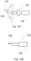
- Figures 4A - 4D schematically illustrate several examples of an inner guide according to the first aspect of the present disclosure.
- the inner guide of these figures may comprise a shape-memory material.
- Figure 4A illustrates an inner guide 120 comprising an electrical resistance 31 embedded in the wall 127 of the inner guide.
- the wall 127 is defined between the inner surface 124 and the outer surface 126.
- the inner guide 120 also comprises an internal passageway for inputting and outputting fluids and/or drugs when the medical device is in the guiding position.
- the electrical resistance 31 may be heated by Joule effect. Two ends of the electrical resistance may be connected to an electrical source to generate an electrical current that produces heat. This heat may thus be transferred to outer tube.
- the electrical resistance 31 runs through the wall 127 in a zig-zag manner.
- the electrical resistance may be arranged in other suitable manners, e.g. in a spiral-like manner.
- a plurality of electrical resistances may be arranged through the wall following an axial direction.
- the internal cavity of the outer tube may match the outer surface 126 of the inner surface when no electric current flows through the electrical resistance 31.
- the inner guide may be heated and the cavity of the outer tube may change its shape in response of this temperature increase.
- Figure 4B illustrates a cross-sectional view of an inner guide 120 comprising a plurality of axially extending thermal fluid paths 32.
- the thermal fluid paths 32 are arranged within the wall 127 defined between the outer surface 126 and the inner surface 124. A heated or a cooled fluid may thus circulate through the thermal fluid paths. The thermal fluid may thus cool or heat the inner guide, and consequently, the outer tube when placed around the inner guide.
- Figure 4C illustrates a cross-sectional view of an inner guide 120 comprising a pair of electrically conductive elements 33, 34 to be in contact with an inner surface of the outer tube.
- the electrically conductive elements 33, 34 may slightly protrude in a radial direction from the outer surface 126 of the inner guide 120.
- An electrical wire 35 is connected to the electrically conductive element 33 and an electrical wire 36 to the electrically conductive element 34.
- These electrical wires 35 and 36 are connected to an electrical source (not shown in Figure 4C ) to generate a voltage difference between the electrical conductive elements 33 and 34.
- the electrical conductive elements 33 and 34 may act as electrodes inducing an electrical current through the outer tuber when the outer tube is in contact with these electrical conductive elements 33 and 34.
- the inner guide may comprise a plurality of pair of electrical conductive elements according to any of the examples herein disclosed.
- the electrically conductive element 33 is adjacent to the distal end 112 and the conductive element 34 adjacent to the rear end 113 of the inner guide.
- the electrical wires 35 and 36 are arranged within the wall 127, however in other examples the electrical wires may be arranged in a dedicated tube inside the passageway 125.
- the inner guide 110 of this figure comprises a distal end portion 111 adjacent to the distal end 112.
- the cross-section of the distal end portion increases from the distal end 112 towards the rear end 113.
- the distal end portion forms a gradually increasing gradient diameter from the distal end.
- the outer tube By having a gradually increasing diameter gradient at the inner guide, the outer tube (and thus the whole medical device) may be more easily introduced and guided through a corporal conduit which reduces the risk of injuring the patient internally. Furthermore, the outer tube may be more precisely placed in the zone to be treated or target zone.
- Figure 4D illustrates a cross-sectional view of a pressure exerting element 200 placed around the inner guide 120.
- the pressure exerting element 200 is a deformable layer arranged on the outer surface 126 of the wall 127 of the inner guide 120.
- a pressure fluid may be directed towards the pressure exerting element 200 for outwardly deforming. This deformation may exert a pressure on the outer tube.
- the pressure exerting element 200 may be clamped between the internal cavity of the outer tube and the outer surface 126 of the inner guide.
- the wall 127 comprises a plurality of fluid pressure channels 38 extending from the rear to the distal end of the inner guide.
- the outer surface 126 comprises a plurality of orifices 40 for guiding a fluid pressure against the pressure exerting element 200.
- Conduits 39 may connect the fluid pressure channels 38 to the orifices 40. The fluid pressure may thus be homogenously directed towards the pressure exerting element to cause a substantially uniformly deformation.
- the pressure exerting element may be heated, e.g. electric current or a heated fluid flowing.
- the pressure exerted by the pressure exerting element may be combined with heat to trigger the change of the shape of the outer tube.
- the pressure fluid flowing through the fluid pressure channels 38 may be heated.
- the inner diameter of the outer tube may be 1 - 2 mm greater that the outer diameter of the internal guide when the medical device is in the guiding position.
- the outer tube may recover an original diameter greater than the diameter at the guiding position.
- the pressure-exerting element may contact both the inner guide and the outer tube thereby facilitating the transmission of heat or an electrical current from the inner guide to the outer tube.
- the pressure-exerting element may according to any of the examples of pressure-exerting elements described in connection to the examples of the second aspect of this disclosure.
- Figure 5 illustrates a flow chart of a method 500 for arranging a transluminal medical device inside a patient's body to reach a target zone according to an example of the first aspect of the present disclosure.
- the method comprises inserting a distal end of an outer tube fitted to an inner guide into a patient's body as represented at block 501.
- the outer tube and the inner guide are thus inserted together.
- the outer tube and the inner guide may be inserted into the patient's body through a corporal conduit or through tissues with an incision.
- the outer tube Prior to inserting the medical device, the outer tube is placed around the inner guide. A cavity of the outer tube may receive the inner guide.
- the outer tube may be connected to the inner guide.
- a stimulus may be applied to the outer tube to change its shape for engaging the inner guide.
- the internal cavity of the outer tube may thus be compressed for fitting the inner guide.
- the stimulus may be applied during the insertion to maintain the outer tube in its deformed shape.
- an electrical current may be applied to the outer tube during guiding inside the patient's body to reach the target zone, e.g. a corporal conduit, to maintain the outer tube in a deformed shape.
- the method 500 further comprises guiding the outer tube and the inner guide to a predetermined position inside the patient's body to reach the target zone as represented at block 502.
- the outer tube and the inner guide may reach the target zone by travelling along corporal conduits and/or through body tissues.
- guiding the outer tube and the inner guide may comprises operating a bendable portion of the inner guide.
- the method 500 comprises causing a change of the shape of the internal cavity of the outer tube in response of a trigger as represented at block 503.
- a trigger may be applied for causing a change of the shape of the internal cavity of the outer tube.
- the trigger may be according to any of the examples herein disclosed.
- the change of the shape may be triggered by a change in temperature and/or pH experienced by the outer tube when reaches the target zone.
- the trigger may be transmitted by the inner guide.
- a trigger actuator may be operated to transmit the trigger through the inner guide towards the outer tube.
- transmitting a trigger may comprise stopping to apply a stimulus on the outer tube. For example, stopping to apply an electrical current to the outer tube. In the absence of an electrical current, the outer tube may recover its original shape.
- the method 500 further comprises removing the inner guide from the outer tube as represented at block 504.
- the change of the internal cavity of the outer tube caused by the trigger allows removing the inner guide.
- the internal cavity of the outer tube thus establishes a fluid communication between the target zone and the outside of the body, e.g. a transluminal access to a corporal conduit, according to any of the examples herein disclosed.
- a treatment e.g. mechanical ventilation, may be administered through the outer tube.
- FIG 6 shows an exploited view of a medical device 100 according to an example of the second aspect of the present disclosure.
- the medical device 100 may comprise an outer tube 110 and an inner guide 120, and may enable a communication between an inside and an outside of the body, e.g. transluminal access to a corporal conduit.
- the outer tube 110 extends from a rear end 113 to a distal end 112.
- the inner guide 120 may comprise a distal end portion 121, i.e. a zone comprising about 1 - 50% of the total length of the inner guide. In some examples, the distal end portion may be of about 10 - 60% of the total length. In some examples, the distal end portion may be of about 20% of the total length.
- the distal end portion 121 may be adjacent to the distal end 112 of the inner guide.
- the inner guide 120 may also comprise a bendable portion, e.g. of about 5 - 10 cm, to facilitate the navigation of the device through sinuous conduits from the insertion point to the zone to be treated, e.g. through existing corporal conduits or through conduits created for reaching the target zone.
- the distal end portion of the inner guide may comprise the bendable portion.
- the inner guide 120 may comprise a plurality of cables (not shown) to move the bendable portion to a required angle.
- the angular range of the bendable portion may be of about 60° - 180°, e.g. 120°.
- the bendable portion may be the distal end portion 121. In another example, the bendable portion may be part of the distal end portion 121.
- the distal end portion may be rigid and sharpened in order to facilitate the insertion and/or the navigation of the device through the tissues.
- the inner guide 120 may be made of any medically suitable material, e.g. polyvinylchloride (PVC) or silicone, a blend or combination thereof, etc.
- the bendable portion may comprise an additional material to be more flexible than the remaining portion of the inner guide 120.
- the inner guide may be expandable.
- the inner guide may be similar to the outer tube according to any of examples herein disclosed.
- the material of the inner guide may be any material that enables the expansion of the inner guide.
- the inner guide 120 may comprise an outer diameter narrow enough to facilitate the insertion and the navigation through a corporal conduit thereby reducing the risk of injuring the patient internally.
- the outer diameter of the inner guide may vary according to the corporal conduit in which the medical device to be inserted. In an example, the outer diameter may be of about 2 - 9 mm. These outer diameters may be used in an endotracheal intubation. In another example, the outer diameter may be of about 0.5 - 3 mm.
- the inner guide 120 may comprise an internal passageway (not shown) to allow fluids such as air to flow bidirectionally, i.e. in and out the conduit.
- the internal passageway may firstly provide an oxygen supply and subsequently a suction force.
- the inner guide 120 may also comprise a pressure-exerting element 200 which may be configured to exert pressure outwardly.
- the pressure-exerting element may be a separate element which may be arranged in the inner guide.
- the pressure-exerting element 200 may be arranged at the outer wall of the inner guide 120 and may extend longitudinally along at least a portion of the distal end portion 121.
- the pressure-exerting element 200 may be made of an expansible material which facilitates the deployment and the retraction, i.e. the unfolding, of the pressure-exerting element repeatedly, e.g. polyvinylchloride (PVC), silicones or polyurethane.
- PVC polyvinylchloride
- the pressure-exerting element 200 may comprise at least two different states: a un-deployed state in which the pressure element is folded and/or does not exert any pressure, and a deployed state in which the pressure element is un-folded and exerts a predetermined pressure.
- the pressure-exerting element may also comprise a partially deployed state in which the pressure element is partially un-folded and/or exerts less pressure than in the deployed state.
- the pressure-exerting element 200 may be an inflatable cuff.
- the pressure-exerting element 200 may be fluid-inflatable, e.g. by (hot) air or (hot) water, and may comprise an inflating lumen to input and output the fluid in order to regulate the deployment.
- the pressure-exerting element 200 may be made of a material that allows transmission of a trigger to the outer tube. The trigger may be triggered from either the pressure element, e.g. if inflated by a heated fluid, or from the inner guide, e.g. if a heated fluid flows through an inner lumen or passageway.
- the inner guide according to any of the disclosed examples may further comprise a visualization system, e.g. an illuminating element, e.g. a led, and/or a camera, to enable direct visualization.
- a visualization system e.g. an illuminating element, e.g. a led, and/or a camera, to enable direct visualization.
- the medical device 100 may also comprise an outer tube 110.
- the outer tube 110 may comprise an inner passageway (not shown) to receive the inner guide 120, as shown in, e.g. Figure 7A .
- the diameter of the outer tube may be bigger, i.e. of about 5 - 50%, than the diameter of the inner guide to enable the insertion of the inner guide therein.
- the diameter of the outer tube may, in the guiding position, provide enough space for at least partially deploying the pressure-exerting element. Therefore, when the inner guide 120 is inserted into the outer tube, the overall outer diameter of the medical device 100 may substantially correspond to the diameter of the inner guide thereby facilitating the insertion into a corporal conduit and also the navigation therethrough.
- the outer tube 110 may comprise a distal end portion 111 which may be of about 1 - 50% of the total length of the outer tube. In an example, the distal end portion 111 may be of about 10 - 20% of the total length of the outer tube. In an example, the distal end portion may have a length of about 1 - 30 cm. In some examples, the distal end portion of the outer tube may be configured to be expanded after receiving a trigger e.g. electric current or heat, or any other suitable trigger. Alternatively, or additionally, the distal end portion may also be expanded upon exertion of a pressure. In an example, the whole outer tube may be expandable.
- a trigger e.g. electric current or heat, or any other suitable trigger.
- the distal end portion may also be expanded upon exertion of a pressure. In an example, the whole outer tube may be expandable.
- the outer tube may comprise a securing element (not shown) for securely fixing the outer tube to a corporal conduit.
- a securing element may comprise two different states: an undeployed state in which the securing element is folded; and a deployed state in which the securing element is un-folded and exerts a pressure, e.g. against the walls of a corporal conduit so as to secure the outer tube therein and/or seal the conduit entirely to prevent fluids from entering thereinto.
- the securing element may be an inflatable cuff.
- the securing element may be fluid-inflatable, e.g. by air or water, and may comprise an inflating lumen to input and output the fluid in order to regulate the deployment state.
- the outer tube may be an endotracheal tube.
- the outer tube may be a catheter providing transluminal access in a corporal conduit, e.g. in a vein or in the urethra.
- Figure 7A depicts a medical device 100 having the inner guide within the outer tube.
- the pressure-exerting element of the inner guide in undeployed state, may be arranged substantially corresponding with the distal tip of the outer tube to facilitate a subsequent releasable anchoring between the inner guide and the outer tube.
- the inner guide may be arranged to slightly protrude a length from the outer tube.
- the bendable portion of the inner guide protrudes from the outer tube 4 - 5 cm.
- the distal tip of the inner guide may be rigid i.e. not bendable, and may be the portion protruding a length from the outer tube.
- Figure 7B depicts a medical device 100 in the guiding position of an example wherein the device has a diameter gradient i.e. the diameter of the outer tube is substantially greater the outer diameter of the inner guide outer diameter.
- Figure 7B also depicts the pressure-exerting element 200 in a deployed state, thereby comprising a progressively increasing diameter gradient 130. Such progressive diameter change facilitates both the insertion and navigation of the medical device, thereby reducing the risk of injuring the patient.
- the medical device 100 may have at least two different positions: a guiding position and an operating position.
- the inner guide may be arranged within the outer tube (see Figure 7A ).
- a length of the pressure-exerting element may be arranged out of the outer tube.
- the pressure-exerting element may be partially deployed thereby releasably coupling inner guide and outer tube together.
- the pressure-exerting element may exert a pressure against the inner walls of the outer tuber, which generates a frictional force to releasably engage with the pressure-exerting element.
- both elements may be introduced and guided together easily through the corporal conduit.
- the pressure-exerting element may be attached, e.g. glued, to the inner guide or be integral part.
- the pressure-exerting element enables a progressive transition from the outer diameter of the inner guide to the outer diameter of the outer tube, which reduces the change of diameter smoothly.
- Such progressively increasing diameter gradient further facilitates the introduction of the medical device 100 into the corporal conduit and also the navigation through the corporal conduit, e.g. by reducing the probabilities to hit the vocal cords.
- the inner guide may be removed from the outer tube, e.g. by folding the pressure-exerting element to the undeployed state.
- the inner passageway of the outer tube may, therefore, be un-occluded for administering the required treatment, e.g. enabling mechanical ventilation of the patient.
- the outer tube 110 may be securely fixed to the corporal conduit, e.g. by deploying a securing element.
- the distal end portion of the outer tube may be made of or may comprise a material that enables at least the distal end portion to expand and/or deform upon exertion of a pressure or upon being triggered thereby providing an outer tube with the same diameter i.e. the diameter of the distal end portion diameter and of the remaining portion of the outer tube may then be equalized.
- the outer tube may be made of a material that enables the whole outer tube to be expanded.
- the expansion of a distal end portion may provide an outer tube with an internal passageway that enables a fluid flow into the conduit.
- the outer tube may comprise a securing element e.g. an inflatable cuff, to securely fix the outer tube to de corporal conduit and may also prevent undesired fluids from entering into the conduit.
- the expanded shape of the outer tube may depend on the pressure-exerting element e.g. the maximum deployment, the arrangement, the length, etc.
- the pressure-exerting element may comprise a length equal or substantially similar to the length of the expandable portion of the outer tube.
- the whole outer tube may be expandable which may provide a compact medical device which may further facilitate the insertion and/or navigation of the device in a corporal conduit.
- the pressure-exerting element and the outer tube may comprise the same length, i.e. to enable the expansion of the whole outer tube.
- the distal end portion of the outer tube 111 or the whole outer tube may be made of a shape-memory material, e.g. PLC-PLLA, Polyurethanes or similar.
- the shape -memory material may enable reducing the diameter of the outer tube (compared to a predefined diameter) before being inserted into a corporal conduit which facilitates the insertion of the medical device.
- a trigger e.g. heat, electricity, a pH change or similar or any combination thereof
- the outer tube may recover a predefined diameter or shape.
- the pressure-exerting element may also contribute to accelerate the conformational change expanding the tube by exerting further pressure.
- the expansion may be triggered by heat and may be enhanced or promoted by the pressure exerted by the pressure-exerting element.
- Being able to set the outer tube in a compact or reduced state during the insertion and navigation enables reducing the overall outer diameter of the medical device which facilitates both the insertion and the navigation through a corporal conduit.
- the medical device 100 may have at least three different positions depending on the configuration of the outer tube: a guiding position, an expanding position and an operating position.
- the pressure-exerting element may be (partially) deployed and/or may exert a minimum pressure to releasably couple the inner guide with the outer tube and also to prevent the distal end portion of the outer tube from being expanded.
- the pressure-exerting element may progressively expand and therefore, gradually increase the exerted pressure, as a result the outer tube may gradually expand or may transmit a trigger to the outer tube thereby triggering the expansion of the outer tube.
- the outer tube may be securely fixed to the corporal conduit and the inner guide may be removed from the outer tube after setting the pressure-exerting element in the undeployed state.
- the internal cavity of the outer tube may therefore be left un-occluded for administering the required treatment, e.g. enabling mechanical ventilation of the patient.
- the medical device 100 may further comprise a control casing.
- the control casing may comprise at least a fluid inputting port, a fluid outputting port, a plurality of actuators and a gripping area.
- the control casing may be according to any of the examples herein disclosed.
- Figure 8 depicts a flow chart of a method 400 for arranging a transluminal medical device in a corporal conduit.
- an inner guide comprising a distal end portion and a pressure element; and an outer tube comprising a distal end portion may be provided.
- the inner guide may further comprise a bendable portion or a cutting element and an internal passageway for the flow of fluids.
- the bendable portion or the cutting element may be arranged at the distal end portion.
- a control casing may also be provided.
- At least the distal end portion of the inner guide may, in block 401, be inserted within or into the distal end portion of the outer tube.
- the inner guide and the outer may, in block 402, be releasably coupled e.g. by partially deploying the tube pressure-exerting element thereby setting the medical device into the guiding position (see e.g. Figure 7B ).
- the inner guide may be arranged to protrude a length from the outer tube.
- the proximal portions of the inner guide and the outer tube may be coupled to the control casing.
- the outer tube may be only releasably coupled to the inner guide via the pressure-exerting element i.e. it may not be coupled to the control casing.
- at least the distal end portions of the inner guide and the outer tube may, in block 403, be inserted together into a corporal conduit.
- the distal end portions of inner guide and the outer tube may, in block 404, be guided to a predetermined location i.e. the zone to be treated or the target zone.
- the bendable portion may be bent, e.g. by actuating a bending actuator, in order to facilitate the navigation of the inner guide, and thus, of the whole medical device, through sinuous conduits.
- the inner guide may, in block 405, be removed from the outer tube after folding the pressure-exerting element to the undeployed state thereby setting the medical device in the operating position. Additionally, the outer tube may be decoupled from the control casing, e.g. actuating a locking actuator. Once in the operating position, only part of the outer tube, e.g. the distal end portion, may remain within the corporal conduit thereby obtaining a transluminal access. At the operating position, the treatment, e.g. mechanical ventilation, may be administered.
- the outer tube may be securely fixed or anchored to the corporal conduit e.g. by deploying a securing element arranged at the outer wall of the outer tube.
- the method 400 may further comprise, in block 405, expanding at least the distal end portion of the outer tube.
- the whole outer tube may be expanded.
- the expansion may be triggered e.g. by the heat from a heated fluid or by electric current.
- the heat and/or the electric current may be transferred from the pressure-exerting element to the outer tube, wherein the pressure element may be connected to the control casing which may generate the trigger.
- the heat or the electric current may be transferred from the inner guide to the outer tube via the pressure-exerting element.
- At least the distal end portion of the outer tube may be expanded e.g. until the predefined diameter or shape.
- the predefined diameter of the distal end zone may correspond to the diameter of the remaining portion of the outer tube.
- Figure9 depicts the distal end portion a medical device 100, i.e. the portion comprising at least the distal end portions 111, 121 of in the inner guide 120 and outer tube 10, respectively; after being inserted into a corporal conduit.
- the medical device 100 is shown in the guiding position i.e. having the pressure-exerting element partially deployed thereby removably coupling the inner guide and the outer tube.
- Figures 10A and 10B depict a medical device 100 having an outer tube with an expandable distal end, the medical device being placed in the required position.
- Figure 10A depicts a medical device 100 with the pressure-exerting element being progressively deployed e.g. by actuating a pressing actuator. As the pressure-exerting element is deployed, its volume and the pressure exerted against the outer tube (see the arrows) increase thereby deforming the distal end portion 111.
- Figure 10B shows the medical device 100 almost in the operating position i.e. as the inner guide is being removed from the outer tube.
- the figure shows the medical device 100 having the distal end portion of the outer tube expanded thereby avoiding undesired fluids to enter into the conduit and also a secure fixation of the tube inside the conduit.
- FIG 11 schematically illustrates a control casing according to an example of the first and/or the second aspect of the present disclosure.
- the control casing 300 of this figure comprises a plurality of actuators, a plurality of internal mechanisms, a plurality of ports and a griping area (not shown) that enables holding the control casing and actuating the plurality of actuators with a single hand.
- the control casing 300 may comprise at least three ports 301, 302, 303 to couple external elements such as fluid inputting or outputting tubes to the casing.
- the port 301 may be an oxygen supply port 301
- the port 302 may be an aspiration or suction port
- the port 303 be a trigger-transmitting port.
- the at least three ports may be configured to be selectively opened/closed.
- the control casing 300 may also comprise a pair of ports, e.g. concentric ports, for coupling the proximal end portions of the inner guide and outer tube, respectively.
- the outer tube may be removably coupled to the control casing.
- the control casing 300 may comprise a trigger actuator 310 e.g. a cam, to activate or deactivate the transmission of the trigger
- the pressure exerted may be regulated by rotating the pressing actuator (see the arrows).
- the cam may comprise a protrusion which may, as consequence of a rotation, elevate an internal mechanism 343 thereby opening the port 303.
- the pressing actuator may regulate the transmission of the trigger.
- the trigger actuator 310 may control the transmission of the trigger through the inner guide to the outer tube.
- the trigger actuator 310 may operate a trigger generator. Examples of trigger generators may be a heater, a pressure generator and/or electrical source.
- the control casing 300 may also comprise a fluid flow actuator 320, e.g. sliding actuator, for selectively inputting/outputting fluids through the inner guide.
- the fluid flow actuator may comprise a protrusion which may elevate, upon movement, an internal mechanism 341, 342 connecting the protrusion of the fluid flow actuator with a port thereby enabling opening the port.
- the fluid flow actuator may comprise three positions: a supply position, a suction position and a neutral position.
- the fluid flow actuator is shown in a neutral position in which there may not be any fluid flow, i.e. there may be no fluid suction nor fluid supply, as the protrusion may not elevate any internal mechanism.
- the actuator may be moved towards the internal mechanism 341, e.g. to the left, thereby opening the port and permitting the fluid supply.
- the actuator may be moved towards the internal mechanism 342, e.g. to the right, thereby opening the port and enabling the fluid suction.
- control casing may comprise two ports: a fluid inlet port and a fluid output port.
- the pressing actuator may, in such cases, be coupled to the inlet port and the fluid output ports and may selectively switch, i.e. open/close the access to each port to e.g. provide oxygen, drugs or to aspirate fluids or take fluid samples.
- the control casing 300 may comprise a bending actuator 330 which may regulate the bending angle of the bendable portion of the inner guide.
- the bending angle may be a predetermined angle between a range of 60° - 180° e.g. 120°.
- the casing may comprise a bending system e.g. a plurality of cables coupled to the bending actuator, in order to set the bendable portion into the required angle.
- the control casing may further comprise a locking element for releasably coupling the outer tube to the control casing.
- the practitioner may actuate a locking actuator (not shown) thereby releasing the outer tube from the control casing and enabling removing the inner guide, thus leaving the outer tube inside the corporal conduit.
- control casing may further comprise resilient elements 350, e.g. springs, for ensuring the contact of the inter mechanisms with the respective actuators.
- resilient elements 350 e.g. springs
- the number of resilient elements and internal mechanisms may depend, e.g. on the number of actuators.
- control casing may comprise a plurality of trigger actuators.
- control casing may further comprise additional triggering actuators which may collaborate with the trigger actuator 303 to enable triggering the expansion of the outer tube, e.g. by enabling a heated fluid to flow through a lumen of the inner guide, and then the heat may be transmitted from the inner guide to the outer tube via the pressure-exerting element.
- additional triggering actuator may allow the flow of electric current and/or heated fluid through the inner guide to change the temperature of the outer guide.
- Figure 12A and 12B schematically illustrates a distal end of an inner guide according to an example of the first and/or the second aspect of the present disclosure.
- the inner guide 120 comprises a protruding length 122 protruding from the outer tube when the medical device is in the guiding position.
- the inner guide has been illustrated in these figures.
- the protruding length 122 of Figure 12A comprises a bendable portion 123 and the protruding length 123 of Figure 12B comprises a cutting element 128.
- An inner guide with a bendable portion 123 may be used for inserting the inner guide (and the outer tube) through existing corporal conduits.
- the bendable portion is flexible so as to adapt its shape to the existing corporal conduits.
- An inner guide with a cutting element 128 may be used for cutting body tissues to create a conduit or passageway between an outside the body and the target zone.
- the protruding length 122 comprises a bendable portion 123.
- the bendable portion of this figure is configured to bend an angle 129.
- the angle 129 may be between 60° and 180°.
- the bendable portion 123 may be inclined at any position within this angle 129.
- the angle 129 substantially correspond to an angle about 180°.
- the bendable portion 123 may be maintained substantially aligned to the longitudinal axis of the inner guide or may be bent up to 90° to each side about the longitudinal axis of the inner guide. The bendable portion 123 of this figure may thus adopt any position between 0° and 90° at different sides about the longitudinal axis.
- the position of the bendable portion i.e. the angle of the bendable portion, may be controlled from a control casing according to any of the examples herein disclosed.
- the control casing may comprise a bendable actuator to control the bending angle of the bendable portion.
- a cable or a plurality of cables may connect the bendable portion to the bendable actuator. For example, if the cable or the plurality of cables are pulled, the bending angle increases.
- the bendable portion may extend about 5 - 10 cm. In some examples, the bendable portion may rotate about the longitudinal axis of the inner guide. This may allow increasing the adaptability to different corporal conduits. Guidance of the outer tube may thus be enhanced.
- the inner guide 120 comprises a cutting element 128 arranged at the protruding length 122.
- This cutting element 128 may be for example a blade or a scalpel. Compared to the bendable portion, the cutting element is rigid and sharpened.
- the cutting element 128 may be used to cut body tissues for reaching the target zone.
- the cutting element maybe made e.g. from metal, to facilitate puncturing body tissues.
- the inner guide having a cutting element may be used to pass through tissues and to access to a corporal conduct such as a vein.
- the outer tube may be an intravascular line or a catheter.
- This type of inner guide may also be used for outer tubes that will function as a thoracic catheter and/or in suprapubic urinary drainages.
- the medical devices according to any of examples herein disclosed may, in some examples, be used to intubate patients.
- the outer tube may be an endotracheal tube.
- the inner guide used for intubating patients may comprise a bendable portion according to any of the examples herein disclosed.
- the medical devices according to any of examples herein disclosed may enable translumilarly accessing a corporal conduit.
Landscapes
- Health & Medical Sciences (AREA)
- Life Sciences & Earth Sciences (AREA)
- Heart & Thoracic Surgery (AREA)
- Engineering & Computer Science (AREA)
- Biomedical Technology (AREA)
- Public Health (AREA)
- General Health & Medical Sciences (AREA)
- Animal Behavior & Ethology (AREA)
- Veterinary Medicine (AREA)
- Surgery (AREA)
- Pulmonology (AREA)
- Hematology (AREA)
- Anesthesiology (AREA)
- Biophysics (AREA)
- Medical Informatics (AREA)
- Nuclear Medicine, Radiotherapy & Molecular Imaging (AREA)
- Molecular Biology (AREA)
- Vascular Medicine (AREA)
- Optics & Photonics (AREA)
- Otolaryngology (AREA)
- Emergency Medicine (AREA)
- Physics & Mathematics (AREA)
- Child & Adolescent Psychology (AREA)
- Pathology (AREA)
- Radiology & Medical Imaging (AREA)
- Media Introduction/Drainage Providing Device (AREA)
- Orthopedic Medicine & Surgery (AREA)
- Business, Economics & Management (AREA)
- General Business, Economics & Management (AREA)
- Epidemiology (AREA)
- Primary Health Care (AREA)
Applications Claiming Priority (3)
| Application Number | Priority Date | Filing Date | Title |
|---|---|---|---|
| EP20382289 | 2020-04-09 | ||
| PCT/EP2021/053408 WO2021204442A1 (en) | 2020-04-09 | 2021-02-12 | A medical device for transluminal access |
| EP21704553.3A EP4132628A1 (de) | 2020-04-09 | 2021-02-12 | Medizinische vorrichtung für transluminalen zugang |
Related Parent Applications (1)
| Application Number | Title | Priority Date | Filing Date |
|---|---|---|---|
| EP21704553.3A Division EP4132628A1 (de) | 2020-04-09 | 2021-02-12 | Medizinische vorrichtung für transluminalen zugang |
Publications (2)
| Publication Number | Publication Date |
|---|---|
| EP4331654A2 true EP4331654A2 (de) | 2024-03-06 |
| EP4331654A3 EP4331654A3 (de) | 2024-06-05 |
Family
ID=70391025
Family Applications (2)
| Application Number | Title | Priority Date | Filing Date |
|---|---|---|---|
| EP23218650.2A Pending EP4331654A3 (de) | 2020-04-09 | 2021-02-12 | Medizinische vorrichtung für transluminalen zugang |
| EP21704553.3A Pending EP4132628A1 (de) | 2020-04-09 | 2021-02-12 | Medizinische vorrichtung für transluminalen zugang |
Family Applications After (1)
| Application Number | Title | Priority Date | Filing Date |
|---|---|---|---|
| EP21704553.3A Pending EP4132628A1 (de) | 2020-04-09 | 2021-02-12 | Medizinische vorrichtung für transluminalen zugang |
Country Status (3)
| Country | Link |
|---|---|
| US (1) | US20230338055A1 (de) |
| EP (2) | EP4331654A3 (de) |
| WO (1) | WO2021204442A1 (de) |
Family Cites Families (16)
| Publication number | Priority date | Publication date | Assignee | Title |
|---|---|---|---|---|
| US4411655A (en) * | 1981-11-30 | 1983-10-25 | Schreck David M | Apparatus and method for percutaneous catheterization |
| US4722335A (en) * | 1986-10-20 | 1988-02-02 | Vilasi Joseph A | Expandable endotracheal tube |
| US6090072A (en) * | 1992-10-15 | 2000-07-18 | Scimed Life Systems, Inc. | Expandable introducer sheath |
| US6706017B1 (en) * | 2000-09-18 | 2004-03-16 | Pavel Dulguerov | Percutaneous ostomy device and method for creating a stoma and implanting a canula |
| EP1651121B1 (de) * | 2003-07-07 | 2007-09-26 | CORAFLO Ltd liab. Co | Hochleistungs-kanülen |
| US7780692B2 (en) * | 2003-12-05 | 2010-08-24 | Onset Medical Corporation | Expandable percutaneous sheath |
| US20050209627A1 (en) * | 2004-03-18 | 2005-09-22 | Kick George F | Expandable medical access device |
| US7328701B2 (en) * | 2004-04-07 | 2008-02-12 | Green Philip A | Variable size endotracheal tube |
| US20060135962A1 (en) * | 2004-09-09 | 2006-06-22 | Kick George F | Expandable trans-septal sheath |
| EP1819391B1 (de) * | 2004-09-09 | 2020-02-19 | Onset Medical Corporation | Expandierbare transluminale schleuse |
| WO2008079828A2 (en) * | 2006-12-20 | 2008-07-03 | Onset Medical Corporation | Expandable trans-septal sheath |
| US10307043B2 (en) * | 2013-03-15 | 2019-06-04 | Richard Rutgers | Endotracheal intubation devices |
| US10194978B2 (en) * | 2014-06-13 | 2019-02-05 | Medtronic Cryocath Lp | Supporting catheter for use for phrenic nerve pacing |
| US10279124B2 (en) * | 2015-01-22 | 2019-05-07 | Aesynt Incorporated | Expanding needle device and method of expansion for the transfer of fluids |
| EP3302311B1 (de) * | 2015-06-03 | 2019-11-20 | Covidien LP | Flexible intravaskuläre behandlungsvorrichtungen |
| US20200030559A1 (en) * | 2018-07-26 | 2020-01-30 | Aninimed, LLC | Expandable endotracheal device |
-
2021
- 2021-02-12 EP EP23218650.2A patent/EP4331654A3/de active Pending
- 2021-02-12 US US17/917,787 patent/US20230338055A1/en active Pending
- 2021-02-12 EP EP21704553.3A patent/EP4132628A1/de active Pending
- 2021-02-12 WO PCT/EP2021/053408 patent/WO2021204442A1/en not_active Ceased
Also Published As
| Publication number | Publication date |
|---|---|
| EP4132628A1 (de) | 2023-02-15 |
| WO2021204442A1 (en) | 2021-10-14 |
| US20230338055A1 (en) | 2023-10-26 |
| EP4331654A3 (de) | 2024-06-05 |
Similar Documents
| Publication | Publication Date | Title |
|---|---|---|
| JP7564903B2 (ja) | 血管への密閉されたアクセス用のシース | |
| JP6946522B2 (ja) | 血管への密閉されたアクセス用のシース | |
| JP6800990B2 (ja) | スコープシステムおよびスコープシステムを使用する方法 | |
| ES2323039T3 (es) | Dispositivos que permiten sellar pasos a traves de tejido y aparato para suministrar dichos dispositivos. | |
| ES2334131T3 (es) | Aplicador y anillo de anastomosis. | |
| JP4570957B2 (ja) | 医療器具送達装置 | |
| JP5111112B2 (ja) | 針誘導治療実行のための装置 | |
| CN106413631B (zh) | 具有射频切割尖端和经加热球囊的导管 | |
| US20170135699A1 (en) | Apparatus and Method for Placement of Device along Wall of a Body Lumen | |
| JP6952049B2 (ja) | 偏向する内視鏡アクセサリチャネル | |
| EP2040788B1 (de) | Papillenspreizer | |
| US20050228443A1 (en) | Device and method for sealing blood vessels | |
| US8287602B2 (en) | Urinary stent | |
| CN109862934A (zh) | 扩张系统 | |
| ES2384203T3 (es) | Fijación de hilo guía | |
| JP4807951B2 (ja) | 位置決め用ポケット付きバルーンカテーテル | |
| EP2512355B1 (de) | Flaches einwege-ventil | |
| CA2482697C (en) | Applier for a surgical device | |
| WO2008142696A1 (en) | Bypass graft device and delivery system and method | |
| JP6488552B2 (ja) | チューブステントデリバリ装置 | |
| EP4331654A2 (de) | Medizinische vorrichtung für transluminalen zugang | |
| WO2018097826A1 (en) | Apparatus and method for placement of device along wall of a body lumen | |
| EP4547133A1 (de) | Vorrichtung und verfahren zur behandlung der harnröhre | |
| CN218870406U (zh) | 切开刀 | |
| CN117653280A (zh) | 切开刀 |
Legal Events
| Date | Code | Title | Description |
|---|---|---|---|
| PUAI | Public reference made under article 153(3) epc to a published international application that has entered the european phase |
Free format text: ORIGINAL CODE: 0009012 |
|
| STAA | Information on the status of an ep patent application or granted ep patent |
Free format text: STATUS: THE APPLICATION HAS BEEN PUBLISHED |
|
| AC | Divisional application: reference to earlier application |
Ref document number: 4132628 Country of ref document: EP Kind code of ref document: P |
|
| AK | Designated contracting states |
Kind code of ref document: A2 Designated state(s): AL AT BE BG CH CY CZ DE DK EE ES FI FR GB GR HR HU IE IS IT LI LT LU LV MC MK MT NL NO PL PT RO RS SE SI SK SM TR |
|
| REG | Reference to a national code |
Ref country code: DE Ref legal event code: R079 Free format text: PREVIOUS MAIN CLASS: A61M0025020000 Ipc: A61M0025010000 |
|
| PUAL | Search report despatched |
Free format text: ORIGINAL CODE: 0009013 |
|
| AK | Designated contracting states |
Kind code of ref document: A3 Designated state(s): AL AT BE BG CH CY CZ DE DK EE ES FI FR GB GR HR HU IE IS IT LI LT LU LV MC MK MT NL NO PL PT RO RS SE SI SK SM TR |
|
| RIC1 | Information provided on ipc code assigned before grant |
Ipc: A61B 90/30 20160101ALI20240430BHEP Ipc: A61M 25/02 20060101ALI20240430BHEP Ipc: A61M 25/09 20060101ALI20240430BHEP Ipc: A61B 1/018 20060101ALI20240430BHEP Ipc: A61B 1/00 20060101ALI20240430BHEP Ipc: A61M 16/04 20060101ALI20240430BHEP Ipc: A61M 25/10 20130101ALI20240430BHEP Ipc: A61M 25/01 20060101AFI20240430BHEP |
|
| STAA | Information on the status of an ep patent application or granted ep patent |
Free format text: STATUS: REQUEST FOR EXAMINATION WAS MADE |
|
| 17P | Request for examination filed |
Effective date: 20241205 |
|
| GRAP | Despatch of communication of intention to grant a patent |
Free format text: ORIGINAL CODE: EPIDOSNIGR1 |
|
| STAA | Information on the status of an ep patent application or granted ep patent |
Free format text: STATUS: GRANT OF PATENT IS INTENDED |
|
| RIC1 | Information provided on ipc code assigned before grant |
Ipc: A61M 25/01 20060101AFI20260224BHEP Ipc: A61M 25/02 20060101ALI20260224BHEP Ipc: A61M 25/09 20060101ALI20260224BHEP Ipc: A61M 25/10 20130101ALI20260224BHEP Ipc: A61M 16/04 20060101ALI20260224BHEP Ipc: A61M 16/06 20060101ALI20260224BHEP Ipc: A61B 1/00 20060101ALI20260224BHEP Ipc: A61B 1/018 20060101ALI20260224BHEP Ipc: A61B 90/00 20160101ALI20260224BHEP Ipc: A61B 90/30 20160101ALI20260224BHEP |
|
| INTG | Intention to grant announced |
Effective date: 20260312 |