EP4331738A1 - Machine à laver et procédé de chargement d'une machine à laver - Google Patents
Machine à laver et procédé de chargement d'une machine à laver Download PDFInfo
- Publication number
- EP4331738A1 EP4331738A1 EP22193491.2A EP22193491A EP4331738A1 EP 4331738 A1 EP4331738 A1 EP 4331738A1 EP 22193491 A EP22193491 A EP 22193491A EP 4331738 A1 EP4331738 A1 EP 4331738A1
- Authority
- EP
- European Patent Office
- Prior art keywords
- containers
- another
- gripper
- distance
- tunnel
- Prior art date
- Legal status (The legal status is an assumption and is not a legal conclusion. Google has not performed a legal analysis and makes no representation as to the accuracy of the status listed.)
- Withdrawn
Links
- 238000005406 washing Methods 0.000 title claims abstract description 80
- 238000000034 method Methods 0.000 title claims description 17
- 239000012636 effector Substances 0.000 claims abstract description 41
- 238000011144 upstream manufacturing Methods 0.000 claims description 5
- 230000001360 synchronised effect Effects 0.000 claims description 2
- 238000004140 cleaning Methods 0.000 description 7
- HEMHJVSKTPXQMS-UHFFFAOYSA-M Sodium hydroxide Chemical compound [OH-].[Na+] HEMHJVSKTPXQMS-UHFFFAOYSA-M 0.000 description 3
- 239000012459 cleaning agent Substances 0.000 description 2
- 235000013305 food Nutrition 0.000 description 2
- 239000011521 glass Substances 0.000 description 2
- 239000011159 matrix material Substances 0.000 description 2
- 239000007864 aqueous solution Substances 0.000 description 1
- 235000013405 beer Nutrition 0.000 description 1
- 210000003477 cochlea Anatomy 0.000 description 1
- 230000001419 dependent effect Effects 0.000 description 1
- 239000000284 extract Substances 0.000 description 1
- 235000011389 fruit/vegetable juice Nutrition 0.000 description 1
- 238000002372 labelling Methods 0.000 description 1
- 235000013336 milk Nutrition 0.000 description 1
- 239000008267 milk Substances 0.000 description 1
- 210000004080 milk Anatomy 0.000 description 1
- 238000012856 packing Methods 0.000 description 1
- 230000000284 resting effect Effects 0.000 description 1
- 235000014214 soft drink Nutrition 0.000 description 1
- XLYOFNOQVPJJNP-UHFFFAOYSA-N water Substances O XLYOFNOQVPJJNP-UHFFFAOYSA-N 0.000 description 1
Images






Classifications
-
- B—PERFORMING OPERATIONS; TRANSPORTING
- B08—CLEANING
- B08B—CLEANING IN GENERAL; PREVENTION OF FOULING IN GENERAL
- B08B9/00—Cleaning hollow articles by methods or apparatus specially adapted thereto
- B08B9/08—Cleaning containers, e.g. tanks
- B08B9/20—Cleaning containers, e.g. tanks by using apparatus into or on to which containers, e.g. bottles, jars, cans are brought
- B08B9/42—Cleaning containers, e.g. tanks by using apparatus into or on to which containers, e.g. bottles, jars, cans are brought the apparatus being characterised by means for conveying or carrying containers therethrough
- B08B9/44—Cleaning containers, e.g. tanks by using apparatus into or on to which containers, e.g. bottles, jars, cans are brought the apparatus being characterised by means for conveying or carrying containers therethrough the means being for loading or unloading the apparatus
-
- B—PERFORMING OPERATIONS; TRANSPORTING
- B08—CLEANING
- B08B—CLEANING IN GENERAL; PREVENTION OF FOULING IN GENERAL
- B08B9/00—Cleaning hollow articles by methods or apparatus specially adapted thereto
- B08B9/08—Cleaning containers, e.g. tanks
- B08B9/20—Cleaning containers, e.g. tanks by using apparatus into or on to which containers, e.g. bottles, jars, cans are brought
- B08B9/42—Cleaning containers, e.g. tanks by using apparatus into or on to which containers, e.g. bottles, jars, cans are brought the apparatus being characterised by means for conveying or carrying containers therethrough
- B08B9/426—Grippers for bottles
Definitions
- the present invention relates to a washing machine for washing (and cleaning) empty containers adapted to be filled with a pourable product, preferably a pourable food product.
- the present invention also relates to a method for loading such a washing machine with empty containers.
- Washing machines are known which are configured for washing and cleaning containers (usually used containers which have been emptied from the pourable product they are adapted to contain) upstream of a filling machine and a labelling machine, in which the containers are respectively filled with the pourable product and labelled with respective labels.
- washing machine is known, e.g. from EP-A-2727660 in the name of the same Applicant.
- a typical washing machine of the above type essentially comprises:
- the chain conveyor comprises a plurality of beams, which are fed at the inlet station by the feeding system with respective rows of containers.
- each beam comprises a plurality of aligned pockets organized in respective longitudinal rows, each pocket being configured to receive one container to be treated at a time, to convey such container from the inlet station to the outlet station through the washing tunnel and along the washing path, and to deliver the respective washed container at the outlet station.
- each beam is discharged of the respective washed containers at the outlet station and then is returned along a return path to the inlet station, where it receives new empty containers to be washed.
- EP-A-3184181 describes a type of feeding system for feeding the containers onto the chain conveyor.
- such feeding system defines a loading apparatus for loading the beams of the washing machine with empty containers to be treated.
- the containers are provided bundled in crates upstream of the washing tunnel.
- the containers 2 are organized in each crate with a certain matrix layout, defined by the structure of the crate itself (e.g. 3x3, 3x4, etc.).
- Said crates are moved by a feed conveyor on which they stand.
- the feeding system of EP-A-3184181 comprises a robotic arm which grasps the containers and extracts them from the crates.
- Such robotic arm then releases the containers into a receiver, in the form of a basket having a series of aligned seats, spaced along a direction parallel to the longitudinal row of each beam so as to match the pitch of the pockets on each beam.
- the pockets layout is reproduced by the receiver seats.
- the receiver loaded with containers at the appropriate pitch is then pivoted for facing the chain conveyor and for feeding the containers into the pockets of one or more beams.
- number 1 indicates as a whole a washing machine for washing empty containers 2 adapted to be filled with a pourable product, preferably a pourable food product such as beer, wine, water, juice, soft drinks, milk or the like.
- a pourable product such as beer, wine, water, juice, soft drinks, milk or the like.
- containers 2 are defined by respective empty bottles (for example, returnable glass bottles) intended to be filled with the pourable product.
- containers 2 may be defined by returnable PET bottles.
- Washing machine 1 comprises:
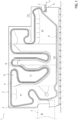
- Conveyor device 4 is defined by an endless conveyor, preferably a chain conveyor, for advancing containers 2 along a closed-loop washing path P inside washing tunnel 3, so as to convey containers 2 from one end of the tunnel 3 to the other end thereof along said conveying direction CD.
- chain conveyor 4 is of the type described in WO-A-2020119958 and comprises:
- each beam 6 comprises a row of pockets 6a aligned orthogonally to washing path P and configured to receive corresponding containers 2.
- chain conveyor 4 comprises a set of pockets 6a arranged as a plurality of consecutive tunnel rows TR, each pocket 6a being configured to receive one container 2 at a time and each tunnel row TR extending longitudinally along a transverse direction TD perpendicular to said conveying direction CD and parallel to washing path P.
- Conveying direction CD is defined by a straight general direction of advancement of containers 2 within washing machine 1 (including feeding system 5).
- each tunnel row TR is spaced with a tunnel pitch W between one another.
- the tunnel pitch W is defined along transverse direction TD.
- tunnel rows TR are arranged at a fixed tunnel distance Z between one another, orthogonally to transverse direction TD (parallel to washing path P).
- Figure 6 schematically shows the above configuration.
- containers 2 carried by a corresponding beam 6 are aligned orthogonally to path P and housed inside the respective pockets 6a, individually.
- Washing machine 1 further comprises an outfeed conveyor 7, which receives rows of cleaned and washed containers 2 from chain conveyor 4 at an outlet station O of washing tunnel 3.
- chain conveyor 4 is configured to convey the containers 2, by means of beams 6 and their pockets 6a, from infeed zone IZ to outlet station O.
- washing path P comprises:
- washing machine 1 comprises in sequence along washing branch Q a plurality of known treatment stations or zones, namely:
- washing machine 1 at the prewash zone P1, first cleaning zone C1, second cleaning zone C2 and final rinsing zone H1 is well-known, for example from WO-A-2020119958 , and therefore will not be described in detail herein.
- a cleaning agent may comprise basic aqueous solutions that include, in particular, sodium hydroxide.
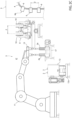
- feeding system 5 comprises:
- seats 10 are arranged (aligned) in at least one receiver row RR extending along transverse direction TD.
- seats 10 are arranged in two receiver rows RR, each extending along transverse direction TD.
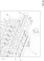
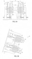
- receiver 8 is defined by a tipping basket with seats 10 and which is tiltable between a resting position ( Figures 2b and 5a ), for receiving containers 2 from robotic arm 11, and a tilted loading position (shown in Figure 2b with dashed lines and in Figure 5b ), for loading containers 2 into pockets 6a.
- feeding system 5 comprises a feed conveyor 12a for advancing or providing crates 12.
- Feeding system 5 further comprises a replenishing conveyor 17 for providing new replenishment containers 2a.
- replenishing conveyor 17 is operatively interposed between robotic arm 11 and receiver 8, with respect to conveying direction CD (as shown in Figure 2c ).
- containers 2 are organized according to a specific predetermined matrix scheme, e.g. 3 by 4 or 4 by 4, and so on.
- robotic arm 11 In order to withdraw containers 2 from one or more crates 12 at a time, robotic arm 11 comprises an end effector or robot hand 13 which has a set of grippers 14 arranged (aligned) in at least one gripper row GR.
- grippers 14 are movable towards and away from one another between:
- second interaxis Y is smaller than first interaxis X.
- second interaxis Y is the smallest interaxis possible between two adjacent grasped containers 2, since in the aforementioned packed layout the containers 2 of the same row contact one another.
- the seats 10 of the at least one receiver row RR are movable, along transverse direction TD, between:
- each container 2 has a central axis B and second interaxis Y is equal to the radial extension of each container 2 with respect to said central axis B.
- each container 2 is defined by a substantially cylindrical glass bottle; hence, when containers 2 grasped by end effector 13 are in the packed layout, i.e. when grippers 14 are moved in the second positions thereby bringing containers 2 in contact with one another, second interaxis Y corresponds to the diameter of each container 2.
- containers 2 in the packed layout contact one another at respective outer lateral surfaces thereof.
- replenishing conveyor 17 can be very simple, without the need for any complicated means (e.g. an infeed cochlea) for sorting containers 2a or for adjusting the pitch of the replenishment containers 2a conveyed thereon.
- end effector 13 is configured so that grippers 14 are controlled in the second position after grasping containers 2 from the one or more crates 12, grippers 14 are already positioned for eventually grasping replenishing containers 2a (if needed), which can then be advanced in a simple row, one after the other and in contact with one another (i.e. with minimum interaxis, namely with second interaxis Y) by replenishment conveyor 17, which is the simplest configuration possible.
- the architecture of replenishment conveyor 17 and of feeding system 5, and ultimately of washing machine 1 is largely simplified.
- the movement of the grippers 14 from the first position to the second position allows for a better control and maneuverability of end effector 13, which conveys containers 2 in a "compact" configuration, with respect to the case in which grippers 14 are immediately spaced at tunnel pitch W by end effector, which would cause a decentered and unbalanced end effector 13 and also determine larger dimensions and less available space for two or more robotic arms 11 operating in parallel at infeed zone IZ.
- end effector 13 does not have to be adapted each time to tunnel pitch W, which would require high precision and starting from a different configuration each time that the crate configuration varies. Packing containers 2 at the second interaxis Y requires less precision, since the movement can automatically stop when containers 2 contact one another.
- receiver 8 complexity of receiver 8 is largely reduced, since seats 10 always receive containers 2 with the same interaxis (i.e. second interaxis Y), so that seats 10 do not have to be adapted each time to a different interaxis which would vary depending on the configuration of crates 12.
- robot arm 11 comprises an actuator 15a coupled to end effector 13 and configured to control the movement of grippers 14 between the first position and the second position.
- actuator 15a is pneumatic.
- actuator 15a is hydrodynamic or electric.
- receiver 8 comprises a pantograph system 16 and seats 10 are mechanically and kinematically coupled to one another by means of pantograph system 16.
- receiver 8 comprises an actuator device 15c configured to control pantograph system 16 for driving a synchronous movement of seats 10 between the receiving position and the releasing position.
- seats 1 may be controlled by means of linear motors, independently from one another.
- grippers 14 are arranged into two gripper rows GR parallel to one another.
- gripper rows GR are movable towards and away from one another, along a second gripper direction G2 perpendicular to first gripper direction G1, between:
- seats 10 are arranged in at least two said receiver rows RR spaced from one another at a distance, along conveying direction CD, corresponding to tunnel distance Z.
- receiver rows RR are fixed at such distance.
- second distance S2 i.e. tunnel distance Z, is greater than first distance S1.
- end effector 13 comprises at least one actuator 15b, preferably two actuators 15b to control the movement of gripper rows GR between the first and second configurations.
- end effector 13 is configured for:
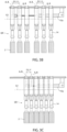
- end effector 13 grasps at least one row (and preferably two rows) of containers 2 with grippers 14 in the first position and containers 2 spaced with first interaxis X, and with the two gripper rows GR in the first configuration, i.e. at first distance S1 from one another. Then, prior to releasing such containers 2, actuator 15 controls grippers 14 in the second position so that containers 2 are spaced with second interaxis Y, contacting one another. Also, gripper rows GR are controlled in the second configuration, i.e. at second distance S2 from one another which corresponds to tunnel distance Z. Prior to receiving containers 2, seats 10 are controlled in their receiving position.
- end effector 3 releases containers 2 into respective seats 10, which are spaced from one another by the minimum distance corresponding to second interaxis Y.
- receiver rows RR are already spaced from one another by tunnel distance Z.
- the distance between receiver rows RR is fixed and equal to tunnel distance Z.
- seats 10 are controlled in their releasing position at which they are spaced of tunnel pitch W.
- receiver 8 is tilted from the rest position to the loading position for releasing containers 2 into pockets 6a.
- receiver 8 preferably includes a plurality of expelling members 18, in the form of movable rods each coaxial with one respective seat 10 and axially movable to push one respective container 2 at a time to extract it from the relative seat 10.
- receiver 8 is preferably slidable, while tilted in the loading position, on a linear guide for temporarily following the advancing movement of beams 6 (and pockets 6a) along path P. More precisely, receiver 8 comprises an actuator for controlling such movement of receiver 8.
- receiver 8 When the speed of receiver rows RR (and seats 10) matches the advancing speed of beams 6, expelling members 18 push the respective containers 2 into pockets 6a.
- containers 2 are released to pockets 6a when seats 10 are in a so-called "tracking" configuration with these latter.
- receiver 8 and conveyor 4 are in a so-called “master and slave” relationship, wherein the receiver 8 defines the slave and conveyor 4 define the master.
- receiver 8 is merely configured to bring the distance between received containers 2 from second interaxis Y to tunnel pitch W, while end effector 13 performs the distancing of the grasped row of containers 2 to match said tunnel distance Z.
- the infeed of new replenishment containers 2a during the loading of the washing machine 1 is largely improved, as well as the flexibility and adaptability of the washing machine 1 to different crate layouts, without unduly increasing the complexity of the feeding system 5.
- replenishing conveyor 17 is advantageously configured for providing new replenishment containers 2a spaced from one another with said second interaxis Y and end effector 13 is configured to grasp (selectively when needed) new replenishment containers 2a from replenishing conveyor 17 with grippers 14 in the second position (i.e. with grippers at second distance D2).
- each seat 10 comprises a pair of gripping pads 19 radially facing one another, with respect to axis C, and arrangeable between an opening position for receiving or releasing the respective container 2 and a closing position (shown in dashed lines in the figure) for gripping container 2.
- At least one adjustable gripping pad 19' of said pair of gripping pads 19 is radially adjustable, when in said closing position, independently from the adjustable gripping pads 19' of the other seats 10 of the same receiver row RR, so as to regulate a gripping pressure thereof (independently from the other pair of gripping pads 19).
- gripping pads 19 are better suited for adapting to possible tolerance errors in the radial dimension of containers 2: in detail, containers 2 of the same receiver row RR can have slightly different radial dimension, i.e. diameter.
- the possibility of finely adjusting the gripping pressure of each seat 10 separately allows to minimize the risk of breaking some containers 2 when gripping them, or of the undesired sliding of some containers 2 when receiver 8 is tilted in the loading position.
- feeding system 5 further comprises a first change station (not shown) at which a support frame (not shown) is located.
- the support frame supports one or more end effectors 13, each having a set of grippers 14 which are adapted to grasp containers 2 of a different format. That is, each end effector 13 supported in support frame is associated to one kind of format of containers 2 to be washed.
- robotic arm 11 is configured to release end effector 13 of one format at first change station and to grip there another end effector 13 of a different format.
- feeding system 5 comprises a second change station (not shown) at which another support frame (not shown) is located.
- Such support frame supports one or more receivers 8, each having a set of seats 10 which are adapted to receive containers 2 of a different format. That is, each receiver 8 supported in support frame is associated to one kind of format of containers 2 to be washed.
- robotic arm 11 is configured to release receiver 8 of one format at second change station and to grip there another receiver 8 of a different format.
- robotic arm 11 is also configured to perform a format change of end effector 13 and of receiver 8.
- feeding system 5 allows to implement a method for loading a washing machine with empty containers adapted to be filled with a pourable product, the method comprising the steps of:
- the method further comprises the step of: f) controlling the seats of the at least one receiver row along said transverse direction, between a receiving position, in which the seats are arranged in a compact configuration at a minimum distance between one another corresponding to said second interaxis for receiving the containers from said end effector, and a releasing position, in which the seats are arranged in an extended configuration at a maximum distance between one another corresponding to said tunnel pitch for releasing the received containers to said pockets.
- the step c) of grasping is carried out by means of a robotic arm comprising an end effector having a set of grippers arranged in at least two gripper rows movable towards and away from one another along a second gripper direction perpendicular to said first gripper direction.
- the method preferably comprises the further steps of:
- the method further comprises the steps of i) advancing new replenishment containers spaced from one another with said second interaxis;
- washing machine 1 and the relative method according to the present invention will be clear from the foregoing description.
- the infeed of new replenishment containers 2a during the loading of the washing machine 1 is largely improved, as well as the flexibility and adaptability of the washing machine 1 to different crate layouts, without unduly increasing the complexity of the feeding system 5.
- washing machine 1 as described herein without, however, departing from the scope of protection as defined in the accompanying claims.
- seats 10 of receiver 8 could be arranged in a number of receiver rows RR different from one or two.
- grippers 14 in end effector 13 could be arranged in a number of gripper rows GR different from one or two.
- the number of receiver rows RR and the number of gripper rows GR coincide.
- feeding system 5 could comprise two or more robotic arms 11 operating in parallel and, correspondingly, two or more receivers 8 operating in parallel and each configured to receive a respective plurality of containers 2 to be washed from one respective robotic arm 11.
Landscapes
- Engineering & Computer Science (AREA)
- Mechanical Engineering (AREA)
- Specific Conveyance Elements (AREA)
Priority Applications (2)
| Application Number | Priority Date | Filing Date | Title |
|---|---|---|---|
| EP22193491.2A EP4331738A1 (fr) | 2022-09-01 | 2022-09-01 | Machine à laver et procédé de chargement d'une machine à laver |
| PCT/EP2023/073943 WO2024047183A1 (fr) | 2022-09-01 | 2023-08-31 | Machine à laver et procédé de commande d'une machine à laver |
Applications Claiming Priority (1)
| Application Number | Priority Date | Filing Date | Title |
|---|---|---|---|
| EP22193491.2A EP4331738A1 (fr) | 2022-09-01 | 2022-09-01 | Machine à laver et procédé de chargement d'une machine à laver |
Publications (1)
| Publication Number | Publication Date |
|---|---|
| EP4331738A1 true EP4331738A1 (fr) | 2024-03-06 |
Family
ID=83151953
Family Applications (1)
| Application Number | Title | Priority Date | Filing Date |
|---|---|---|---|
| EP22193491.2A Withdrawn EP4331738A1 (fr) | 2022-09-01 | 2022-09-01 | Machine à laver et procédé de chargement d'une machine à laver |
Country Status (2)
| Country | Link |
|---|---|
| EP (1) | EP4331738A1 (fr) |
| WO (1) | WO2024047183A1 (fr) |
Cited By (1)
| Publication number | Priority date | Publication date | Assignee | Title |
|---|---|---|---|---|
| DE102024119120A1 (de) * | 2024-07-05 | 2026-01-08 | Krones Aktiengesellschaft | Behälterbehandlungsanlage mit Behälterreinigungsvorrichtung und Behälterförderer |
Citations (5)
| Publication number | Priority date | Publication date | Assignee | Title |
|---|---|---|---|---|
| EP2727660A1 (fr) | 2012-11-05 | 2014-05-07 | Sidel S.p.A. Con Socio Unico | Unité de traitement de récipients et procédé pour la reconfiguration d'une unité de traitement de récipients |
| EP3184181A1 (fr) | 2015-12-23 | 2017-06-28 | Gebo Packaging Solutions Italy SRL | Chargement d'une unité de lavage |
| WO2020119958A1 (fr) | 2018-12-13 | 2020-06-18 | Sidel End Of Line & Tunnels Solutions Srl | Machine à laver pour laver des récipients vides et son procédé de fonctionnement |
| US20210323777A1 (en) * | 2020-04-16 | 2021-10-21 | A.C.M.I. - Societa' Per Azioni | Manipulation head for objects |
| CN113911722A (zh) * | 2021-10-29 | 2022-01-11 | 湖北楚大智能装备有限公司 | 一种玻璃瓶夹取装置、使用方法及系统 |
-
2022
- 2022-09-01 EP EP22193491.2A patent/EP4331738A1/fr not_active Withdrawn
-
2023
- 2023-08-31 WO PCT/EP2023/073943 patent/WO2024047183A1/fr not_active Ceased
Patent Citations (5)
| Publication number | Priority date | Publication date | Assignee | Title |
|---|---|---|---|---|
| EP2727660A1 (fr) | 2012-11-05 | 2014-05-07 | Sidel S.p.A. Con Socio Unico | Unité de traitement de récipients et procédé pour la reconfiguration d'une unité de traitement de récipients |
| EP3184181A1 (fr) | 2015-12-23 | 2017-06-28 | Gebo Packaging Solutions Italy SRL | Chargement d'une unité de lavage |
| WO2020119958A1 (fr) | 2018-12-13 | 2020-06-18 | Sidel End Of Line & Tunnels Solutions Srl | Machine à laver pour laver des récipients vides et son procédé de fonctionnement |
| US20210323777A1 (en) * | 2020-04-16 | 2021-10-21 | A.C.M.I. - Societa' Per Azioni | Manipulation head for objects |
| CN113911722A (zh) * | 2021-10-29 | 2022-01-11 | 湖北楚大智能装备有限公司 | 一种玻璃瓶夹取装置、使用方法及系统 |
Cited By (2)
| Publication number | Priority date | Publication date | Assignee | Title |
|---|---|---|---|---|
| DE102024119120A1 (de) * | 2024-07-05 | 2026-01-08 | Krones Aktiengesellschaft | Behälterbehandlungsanlage mit Behälterreinigungsvorrichtung und Behälterförderer |
| EP4678304A1 (fr) * | 2024-07-05 | 2026-01-14 | Krones Ag | Installation de traitement de récipients avec dispositif de nettoyage de récipients et convoyeur de récipients |
Also Published As
| Publication number | Publication date |
|---|---|
| WO2024047183A1 (fr) | 2024-03-07 |
Similar Documents
| Publication | Publication Date | Title |
|---|---|---|
| KR102474766B1 (ko) | 컨테이너용 이송 시스템 | |
| US6520317B2 (en) | Packaging and casing system | |
| US7661522B2 (en) | Container processing machine, and method for loading and unloading a container processing machine | |
| EP2889238A1 (fr) | Dispositif de transfert d'articles le long d'un trajet | |
| JPH01199825A (ja) | 物品を供給装置から排送装置へと移送するための方法および装置 | |
| US7624856B2 (en) | Method for conveying containers through operating stations and a multiple conveyor for actuating the method | |
| JPH10506360A (ja) | 移動するコンベヤまで容器を搬送する装置 | |
| US8813945B2 (en) | Apparatus and method for treating containers with rotation of the containers | |
| JPH0752917A (ja) | 包装機械 | |
| US20090312865A1 (en) | Article metering system | |
| JPH07165335A (ja) | 搬送容器からの容器の取出装置 | |
| US20250197132A1 (en) | Method and device for buffering containers in a container treatment plant | |
| EP4331738A1 (fr) | Machine à laver et procédé de chargement d'une machine à laver | |
| CN114502471A (zh) | 物品拾取和处理设备 | |
| US11286072B2 (en) | Device and method for packaging products in pre-made packages | |
| CN115043188A (zh) | 机器人整理机 | |
| HU224284B1 (hu) | Csomagológép és eljárás áruk kartondobozokba csomagolásához, valamint vezérlőberendezés és vezérlési eljárás a csomagológép működésének vezérléséhez | |
| CN102328809A (zh) | 容器处理设施及处理容器的方法 | |
| EP3184181B1 (fr) | Chargement d'une unité de lavage | |
| JP7582975B2 (ja) | 特に製薬産業におけるボトルを充填する装置のための搬送方法及び搬送システム | |
| WO2002004327A2 (fr) | Tete de transfert de contenants, notamment des bouteilles, dans un palettiseur | |
| EP1201599A1 (fr) | Système de transport d'objets à traiter | |
| EP2399681B1 (fr) | Procédé et appareil pour remplir et rincer des récipients et installation intégrée pour souffler, rincer et remplir des récipients | |
| EP1094967A1 (fr) | Ligne de manipulation de tubes | |
| EP0686561B1 (fr) | Dispositif d'emballage |
Legal Events
| Date | Code | Title | Description |
|---|---|---|---|
| PUAI | Public reference made under article 153(3) epc to a published international application that has entered the european phase |
Free format text: ORIGINAL CODE: 0009012 |
|
| STAA | Information on the status of an ep patent application or granted ep patent |
Free format text: STATUS: THE APPLICATION HAS BEEN PUBLISHED |
|
| AK | Designated contracting states |
Kind code of ref document: A1 Designated state(s): AL AT BE BG CH CY CZ DE DK EE ES FI FR GB GR HR HU IE IS IT LI LT LU LV MC MK MT NL NO PL PT RO RS SE SI SK SM TR |
|
| STAA | Information on the status of an ep patent application or granted ep patent |
Free format text: STATUS: THE APPLICATION IS DEEMED TO BE WITHDRAWN |
|
| 18D | Application deemed to be withdrawn |
Effective date: 20240907 |