EP4331776B1 - Dispositif de fourniture d'outils - Google Patents
Dispositif de fourniture d'outils Download PDFInfo
- Publication number
- EP4331776B1 EP4331776B1 EP22193176.9A EP22193176A EP4331776B1 EP 4331776 B1 EP4331776 B1 EP 4331776B1 EP 22193176 A EP22193176 A EP 22193176A EP 4331776 B1 EP4331776 B1 EP 4331776B1
- Authority
- EP
- European Patent Office
- Prior art keywords
- tool
- provision device
- receptacle
- pushbutton
- container
- Prior art date
- Legal status (The legal status is an assumption and is not a legal conclusion. Google has not performed a legal analysis and makes no representation as to the accuracy of the status listed.)
- Active
Links
Images


Classifications
-
- B—PERFORMING OPERATIONS; TRANSPORTING
- B25—HAND TOOLS; PORTABLE POWER-DRIVEN TOOLS; MANIPULATORS
- B25H—WORKSHOP EQUIPMENT, e.g. FOR MARKING-OUT WORK; STORAGE MEANS FOR WORKSHOPS
- B25H3/00—Storage means or arrangements for workshops facilitating access to, or handling of, work tools or instruments
- B25H3/02—Boxes
- B25H3/021—Boxes comprising a number of connected storage elements
- B25H3/023—Boxes comprising a number of connected storage elements movable relative to one another for access to their interiors
- B25H3/028—Boxes comprising a number of connected storage elements movable relative to one another for access to their interiors by sliding extraction from within a common frame
-
- B—PERFORMING OPERATIONS; TRANSPORTING
- B62—LAND VEHICLES FOR TRAVELLING OTHERWISE THAN ON RAILS
- B62B—HAND-PROPELLED VEHICLES, e.g. HAND CARTS OR PERAMBULATORS; SLEDGES
- B62B3/00—Hand carts having more than one axis carrying transport wheels; Steering devices therefor; Equipment therefor
- B62B3/002—Hand carts having more than one axis carrying transport wheels; Steering devices therefor; Equipment therefor characterised by a rectangular shape, involving sidewalls or racks
- B62B3/005—Details of storage means, e.g. drawers, bins or racks
-
- B—PERFORMING OPERATIONS; TRANSPORTING
- B65—CONVEYING; PACKING; STORING; HANDLING THIN OR FILAMENTARY MATERIAL
- B65D—CONTAINERS FOR STORAGE OR TRANSPORT OF ARTICLES OR MATERIALS, e.g. BAGS, BARRELS, BOTTLES, BOXES, CANS, CARTONS, CRATES, DRUMS, JARS, TANKS, HOPPERS, FORWARDING CONTAINERS; ACCESSORIES, CLOSURES, OR FITTINGS THEREFOR; PACKAGING ELEMENTS; PACKAGES
- B65D25/00—Details of other kinds or types of rigid or semi-rigid containers
- B65D25/02—Internal fittings
- B65D25/10—Devices to locate articles in containers
- B65D25/103—V-shaped elements, e.g. racks, protuberances projecting from a supporting surface, supporting the articles locally at its sides
- B65D25/105—V-shaped elements, e.g. racks, protuberances projecting from a supporting surface, supporting the articles locally at its sides and retaining it by snap-action, e.g. clips
-
- B—PERFORMING OPERATIONS; TRANSPORTING
- B65—CONVEYING; PACKING; STORING; HANDLING THIN OR FILAMENTARY MATERIAL
- B65D—CONTAINERS FOR STORAGE OR TRANSPORT OF ARTICLES OR MATERIALS, e.g. BAGS, BARRELS, BOTTLES, BOXES, CANS, CARTONS, CRATES, DRUMS, JARS, TANKS, HOPPERS, FORWARDING CONTAINERS; ACCESSORIES, CLOSURES, OR FITTINGS THEREFOR; PACKAGING ELEMENTS; PACKAGES
- B65D81/00—Containers, packaging elements, or packages, for contents presenting particular transport or storage problems, or adapted to be used for non-packaging purposes after removal of contents
- B65D81/02—Containers, packaging elements, or packages, for contents presenting particular transport or storage problems, or adapted to be used for non-packaging purposes after removal of contents specially adapted to protect contents from mechanical damage
- B65D81/05—Containers, packaging elements, or packages, for contents presenting particular transport or storage problems, or adapted to be used for non-packaging purposes after removal of contents specially adapted to protect contents from mechanical damage maintaining contents at spaced relation from package walls, or from other contents
- B65D81/127—Containers, packaging elements, or packages, for contents presenting particular transport or storage problems, or adapted to be used for non-packaging purposes after removal of contents specially adapted to protect contents from mechanical damage maintaining contents at spaced relation from package walls, or from other contents using rigid or semi-rigid sheets of shock-absorbing material
- B65D81/133—Containers, packaging elements, or packages, for contents presenting particular transport or storage problems, or adapted to be used for non-packaging purposes after removal of contents specially adapted to protect contents from mechanical damage maintaining contents at spaced relation from package walls, or from other contents using rigid or semi-rigid sheets of shock-absorbing material of a shape specially adapted to accommodate contents, e.g. trays
-
- G—PHYSICS
- G01—MEASURING; TESTING
- G01G—WEIGHING
- G01G19/00—Weighing apparatus or methods adapted for special purposes not provided for in the preceding groups
- G01G19/40—Weighing apparatus or methods adapted for special purposes not provided for in the preceding groups with provisions for indicating, recording, or computing price or other quantities dependent on the weight
- G01G19/413—Weighing apparatus or methods adapted for special purposes not provided for in the preceding groups with provisions for indicating, recording, or computing price or other quantities dependent on the weight using electromechanical or electronic computing means
- G01G19/414—Weighing apparatus or methods adapted for special purposes not provided for in the preceding groups with provisions for indicating, recording, or computing price or other quantities dependent on the weight using electromechanical or electronic computing means using electronic computing means only
-
- G—PHYSICS
- G01—MEASURING; TESTING
- G01G—WEIGHING
- G01G19/00—Weighing apparatus or methods adapted for special purposes not provided for in the preceding groups
- G01G19/52—Weighing apparatus combined with other objects, e.g. furniture
-
- B—PERFORMING OPERATIONS; TRANSPORTING
- B62—LAND VEHICLES FOR TRAVELLING OTHERWISE THAN ON RAILS
- B62B—HAND-PROPELLED VEHICLES, e.g. HAND CARTS OR PERAMBULATORS; SLEDGES
- B62B2202/00—Indexing codes relating to type or characteristics of transported articles
- B62B2202/48—Tools
-
- B—PERFORMING OPERATIONS; TRANSPORTING
- B65—CONVEYING; PACKING; STORING; HANDLING THIN OR FILAMENTARY MATERIAL
- B65D—CONTAINERS FOR STORAGE OR TRANSPORT OF ARTICLES OR MATERIALS, e.g. BAGS, BARRELS, BOTTLES, BOXES, CANS, CARTONS, CRATES, DRUMS, JARS, TANKS, HOPPERS, FORWARDING CONTAINERS; ACCESSORIES, CLOSURES, OR FITTINGS THEREFOR; PACKAGING ELEMENTS; PACKAGES
- B65D2255/00—Locking devices
-
- B—PERFORMING OPERATIONS; TRANSPORTING
- B65—CONVEYING; PACKING; STORING; HANDLING THIN OR FILAMENTARY MATERIAL
- B65D—CONTAINERS FOR STORAGE OR TRANSPORT OF ARTICLES OR MATERIALS, e.g. BAGS, BARRELS, BOTTLES, BOXES, CANS, CARTONS, CRATES, DRUMS, JARS, TANKS, HOPPERS, FORWARDING CONTAINERS; ACCESSORIES, CLOSURES, OR FITTINGS THEREFOR; PACKAGING ELEMENTS; PACKAGES
- B65D2313/00—Connecting or fastening means
- B65D2313/04—Connecting or fastening means of magnetic type
Definitions
- the invention relates to a tool provision device, in particular a workshop trolley, a workbench or a tool cabinet, according to the features in the preamble of claim 1.
- a tool provision device in particular a workshop trolley, a workbench or a tool cabinet, according to the features in the preamble of claim 1.
- Such a device is already known from US 2019/279288 A1 known.
- Workshop trolleys workbenches or tool cabinets are widely used.
- Workshop trolleys of the common design have a housing that can be moved on rollers, in which a number of containers in the form of drawers are arranged one above or one below the other.
- the drawers are usually mounted on side rails and are pulled out of the housing from the front.
- Workbenches also have a housing with drawers arranged in it.
- Tool provision devices have proven themselves in practice. They are used to hold and/or transport a wide variety of tools that can be stored in storage systems. Various systems are known in this context that are intended to enable identification and recording of tools and seamless registration of tool removal and return processes.
- DE 10 2007 017 207 A1 In this context, suggests assigning each tool a fixed storage location and providing it with a transponder that can be linked to a receiver located at the storage location to exchange signals. This should make it possible to constantly and permanently check whether a tool is in place or in use. Furthermore, all authorized tool users should be assigned a transponder and access to the tool storage should only be possible using the transponder.
- Each tool storage location includes an individually designed recess for receiving a specific tool, the shape of the recess being adapted to the shape of the tool. Furthermore, detection means for detecting the presence of tools and means for transmitting signals from the detection means to a data processing device are provided. The data processing device receives the signals from the detection means and records the removal and return of tools. The presence and/or absence of tools is displayed via an output device.
- a tool supply device with a tool carrier which has a recess for receiving a tool, in particular a hand tool.
- a sensor unit is arranged on a side of the tool carrier opposite the tool-side recess. The sensor unit is intended to detect the presence and/or absence of a tool through the tool carrier.
- a method and a system for monitoring the presence of a tool at a given position also describes the DE 10 2008 031 372 A1 .
- the US 2009/0072029 A1 discloses an inventory control system for a tool provision device with a plurality of storage locations for inventory items, specifically receptacles for tools, and a monitoring system for monitoring the removal and insertion of tools from or into the receptacles.
- each tool is assigned a specific location.
- Each location is assigned a sensor that is connected to an evaluation device that evaluates the presence or absence of a tool to be dispensed.
- a system for tracking and controlling access to objects is based on the US 7,317,393 B2
- the system includes a storage unit in the form of a lockable cabinet for storing, issuing and receiving items.
- a computer control is linked to the cabinet and includes a user interface for identifying or verifying a user. The computer control is also used to monitor the removal and return of items.
- the invention is based on the object of improving a tool provision device with a tool identification and monitoring system with a simple design in terms of reliability and overall practicality.
- a tool provision device is in particular a workshop trolley, a workbench or a tool cabinet.
- the tool provision device has a housing and containers arranged therein, wherein at least one tool carrier is provided in a container, which has several receptacles for tools.
- a detector is assigned to each receptacle to detect the presence of a tool in the receptacle.
- the containers are drawers or compartments.
- the detector has a pushbutton switch with a pushbutton element, whereby the pushbutton element passes through an opening in the tool carrier and projects with an active surface into the holder for a tool.
- the active surface can be provided in particular on the front side of the pushbutton element but also on a side surface of the pushbutton element or can be formed by this. It is essential that the The active surface extends into the holder in such a way that the pushbutton switch is activated by an inserted tool and is deactivated when the tool is removed.
- the opening is a breakthrough through the wall of the tool carrier below the receptacle, with the probe element protruding from below through the base of a receptacle into the receptacle.
- receptacles of the second type in which the probe element protrudes laterally, i.e. from a side wall, into the receptacle.
- the opening for the probe element is a breakthrough or cutout through the wall of the tool carrier to the side of the receptacle.
- the invention provides that a holder element is arranged in at least one receptacle, which acts as a pressure amplifier for a tool.
- the first type of holder and the second type of holder in the tool carrier differ in the arrangement and design of the opening for the probe element.
- the opening for the probe element is an opening in the wall of the tool carrier below the holder. The probe element is guided from below through the base of the holder and protrudes into the holder. When a tool is inserted, the probe element is moved vertically and pressed downwards by the weight. When the corresponding tool is removed, the probe element moves upwards.
- First-type holders are intended in particular for hand tools such as torque wrenches, hammers or pliers.
- the opening for the probe element is a hole in the wall of the tool holder on the side of the holder.
- the hole can extend from the bottom of the tool holder to the side wall of the holder.
- the probe element protrudes laterally through the wall of the tool holder into the holder and contacts an inserted tool from the side.
- the probe element comes into contact with a section of the tool for installation, which extends adjacent to the side wall of the holder and essentially parallel thereto.
- the second type of holders are particularly intended for tools such as sockets, socket wrenches or socket inserts or screw bits.
- the pushbutton switch is the detection element that is activated by pressing its pushbutton element and deactivated again by releasing it. In this way, the presence or absence of a tool in a holder can be detected.
- the weight of a tool in a holder presses the pushbutton element of the pushbutton switch and activates it.
- the pressure causes the pushbutton switch to establish a connection that is interrupted again when the pushbutton switch is released, i.e. when a tool is removed.
- the pushbutton switch returns to its original position thanks to a spring integrated in the pushbutton switch and acting on the pushbutton element.
- the position of the probe element protruding into the holder is the starting position of a pushbutton switch; the position of the probe element lowered or pressed by a tool is the trigger position of the pushbutton switch, whereby a signal is generated and transmitted to a data processing unit.
- a tool comes into contact with the effective surface of the probe element protruding through the base of a holder and presses it down.
- an inserted tool comes into contact with the effective surface of the probe element protruding through an opening in the side wall of the holder and pushes or presses the probe element to the side.
- the invention makes use of an electro-mechanical detection of a tool in a holder, in which the detector or the push button of the detector comes into contact with a tool and is immediately activated by the tool itself.
- the probe element is a plunger, in particular a spring-loaded plunger or a leg, in particular a spring leg or a lever, in particular a spring lever.
- the sensing elements can have a specific surface contour adapted to a tool type in order to be able to feel the position of the tools better.
- the surface contour can be adapted to an offset screwdriver or a hexagonal Allen key.
- a further advantageous aspect of the invention provides that the at least one pushbutton switch is arranged in a support body.
- a support body Preferably, several pushbutton switches are arranged in a support body, advantageously in series and positioned on a circuit board.
- the circuit board with the pushbutton switches is accommodated in the support body and is arranged with the support body in the tool carrier.
- the arrangement is such that the individual touch elements of the pushbutton switches each pass through an opening in the tool carrier and protrude into the receptacle with their active surface.
- the support body can form part of the tool carrier.
- parts of the support body form side surfaces of the receptacle of the second type.
- the opening is a hole in the wall of the tool carrier in the area below the holder.
- the opening is adapted to the dimensions of the pushbutton element of a push button switch so that it can be easily moved back and forth in the opening.
- the tool carrier itself is particularly preferably formed by a soft foam insert.
- a holder has a recess in the tool carrier that is adapted to the shape of a specific tool.
- the opening is a hole in the wall of the tool carrier at the side of the holder or a lateral cutout in the Tool carrier.
- the probe element is designed as a lever or spring leg, in particular a spring-loaded lever, and protrudes laterally into the holder.
- Identification features for the individual tools can be assigned to the holders in the tool carrier. This can be a label, such as a tool article number, but also a symbol or a pictogram. Using the identification features, a tool can be assigned to a holder quickly and easily.
- the combination of several pushbutton switches is advantageous, whereby pushbutton switches are provided whose pushbutton elements protrude from below into the receptacle, i.e. through the bottom of a receptacle, and furthermore detectors with pushbutton switches are provided whose pushbutton elements protrude laterally into a receptacle, whereby the pushbutton elements, with their active surfaces, penetrate openings in the form of perforations in a side wall of the receptacle of the tool carrier.
- the pushbutton switch is supported at least indirectly on the bottom of a container, in particular a drawer. This is advantageous for force introduction, sensitivity and triggering of the detectors.
- One or more pushbutton switches can be arranged in a support body or accommodated in a support body. The pushbutton switch is supported indirectly on the bottom of a container above the support body. Furthermore, a support body can be supported at least indirectly on the bottom of a container.
- An advantageous embodiment provides that a pushbutton element or a pushbutton switch is integrated with the pushbutton element in a housing.
- the housing forms the support body for the pushbutton element and improves functional reliability.
- the housing with the integrated stylus is advantageously located directly on a circuit board. In particular, the housing ensures the functionality and mechanical mobility of a pushbutton element.
- a particularly advantageous embodiment in practice provides that the pushbutton switch is attached to a circuit board which is arranged on the bottom of the container below the tool carrier.
- a tool carrier has several receptacles, with a detector assigned to each receptacle.
- all detectors are arranged in a horizontal plane. This increases the reliability and practicality of the detectors and the combination of several detectors in one detector surface.
- a further advantage is that the sensing elements, as well as the circuit boards, do not require any additional space or only insignificantly more space in a container, since the components are essentially positioned in or under the tool carrier, in particular in a tool carrier formed by a soft foam insert.
- the pushbuttons of the detectors are triggered or activated in particular by the weight of a tool. If the weight of a tool itself is not sufficient, the invention provides that a holder element is arranged in at least one receptacle, in particular a clamp-shaped holder element or a magnetically acting holder element, i.e. a magnet holder element.
- the holder element is intended and designed so that a tool must be placed in a receptacle using a certain amount of force. This amount of force actuates the pushbutton via the tool.
- the holder element acts as a pressure amplifier for the tool in the receptacle.
- the holder element holds the tool in the receptacle and thus ensures that the pushbutton remains in the trigger position as long as a tool is arranged in the receptacle.
- the tool is fixed in a receptacle.
- holder elements in the form of magnetic holders are integrated into a holder to press the tools into position on the push buttons. This is also advantageous in the event of vibrations and/or movements of the tool supply device, for example a workshop trolley.
- the arrangement or number of holders with an integrated holding element which acts as a pressure amplifier for a tool, is coordinated with the equipment of the tools to be accommodated in the container or drawer, their geometry and/or weight. The same applies to the holders of the first type and the holders of the second type.
- a data processing unit is provided to record and evaluate the signals generated by one or more detectors and to process them further. This is intended and designed to receive signals from the detector(s) and to record and document the removal and return of a tool.
- the tools are identified using the data processing unit. This is done by evaluating and processing the signals received from the detectors and assigning them to the receptacles in the tool carrier.
- the data processing unit can also be used to record tool usage data, such as the issue duration or time, but also inspection intervals of the tools or their calibration and/or tool status data as well as tool user data.
- a signal is generated by the detector assigned to the respective holder by moving the touch element over the push button.
- These signals are registered by the software and electronics that form part of the data processing unit.
- the absence and presence of a tool is transmitted to an evaluation unit; in particular, the information can be displayed on a WLAN-connected device.
- the tool can be identified and, in addition to the usual information such as tool type and age, etc., further information can also be stored for the tool, such as test, inspection or calibration intervals or usage time.
- the tool inventory is monitored and managed automatically. An automatic and immediate inventory of the tools in the tool supply device is carried out. Access control and traceability is simplified. Identification and management of tools takes place in real time. User recognition at the tool provision device can be achieved by means of a personalized access card or a personal code.
- the identification and management system includes system software that is activated when the tool provision device is used. A tool can be removed by the user or returned after use. The removal or return is saved. Associated usage processes or times are determined and archived. An automatic inventory can be taken when individual drawers are closed or when the tool provision device is locked.
- An advantageous embodiment provides that the outline of one or more tools is shown on the circuit boards.
- the outline represents a curve for the viewer that separates the object from its surroundings. This measure makes it easier to assemble the circuit boards themselves but also to arrange the tool carriers on the circuit boards in a drawer.
- circuit boards can also be used in which the outline of the tools is not shown on the surface of the circuit boards.
- circuit boards are arranged next to one another on the bottom of a drawer. It is expedient if each circuit board has a module size adapted to the dimensions of the container, so that the circuit boards together cover the bottom area. In particular, two, three or four circuit boards are arranged next to one another on the bottom area of a container.
- a measure that further increases the practicality of the tool provision device provides that one or more cable support devices are arranged in the housing for electrical connection lines.
- the cable support device serves in particular to hold and guide electrical connection lines between the circuit boards, in the containers and between the circuit boards and the data processing unit.
- the cable support device enables movement of the electrical connecting cables, especially when pulling out and pushing back the drawers.
- movable cable support devices are arranged in the housing. These carry the power supply line and the data communication lines to each individual container, in particular each individual drawer. Accordingly, one cable support device is provided for each container.
- a cable duct in particular made of sheet metal, i.e. preferably a sheet metal component, is also firmly attached, in particular welded.
- the individual movable cable support devices, including electrical lines, i.e. cables, are screwed or riveted to this duct during assembly.
- the cable arms of the cable support device are attached to the containers with detachable connecting elements, for example screws. This facilitates the assembly and also any possible replacement of the cable support device or both.
- a further advantageous aspect of the invention provides a locking system by means of which the containers in the housing can be centrally locked.
- the locking system can preferably be operated from a central lock unit.
- the locking system can be opened or closed without contact, for example by means of an RFID transponder.
- the electronic locking system preferably has an electric servomotor by means of which a locking bar can be moved and the lock can be transferred to the open or closed position. Operation is carried out via user identification, for example a PIN code or an identification card. This can be an RFID sensor or transponder or similar identification tags (tokens). Tool user data can also be recorded using an appropriately designed transmitter-receiver system.
- the locking system can also automatically switch to the locking state under software control. This can be done on a time-controlled basis, for example.
- a timer is integrated for this purpose so that the tool supply device is automatically closed and switches to the locking state after a predetermined period of time in which it has not been used.
- the locking system belonging to the tool provision device according to the invention has a mechanical emergency release, via which the locking of the tool provision device can be actuated in the event of failure of the electronic locking system.
- the emergency release comprises a cylinder lock.
- the tool provision device has functional electronics, wherein the functional electronics control at least one actuator.
- the actuator is provided in particular for actuating a locking bar of the locking system.
- the functional electronics can also have a wireless communication module. This is in particular a Bluetooth or WLAN module.
- the wireless communication module is an integral part of the data processing unit.
- the tool provision device can provide a device-related WLAN network with a wireless access point, i.e. a wireless access point that acts as an interface for wireless communication devices.
- a wireless access point i.e. a wireless access point that acts as an interface for wireless communication devices.
- communication between the tool provision device and a mobile device such as a smartphone or smart tablet, or other operators is possible.
- a mobile device such as a smartphone or smart tablet, or other operators is possible.
- Several tool provision devices can also be connected in a network, so that central or decentralized monitoring is possible.
- a display that communicates with a data processing unit.
- the presence or absence of tools, but also tool usage data and/or user data can be displayed via the display.
- the display is preferably arranged or integrated in a functional area on the tool provision device.
- the display shows the status of the tools and/or the closed state of the tool provision device and similar, such as the battery charge level.
- Information about peripheral components of the tool provision device, such as data processing cables, in particular their presence or absence, as well as any operating modes, can also be detected and displayed via the data processing unit and the display.
- the tool supply device is equipped with an electrical power supply.
- the power supply is expediently provided by a power storage device, in particular a lithium-ion battery.
- the battery can be mounted in an easily accessible holder on the tool supply device. This holder enables a battery to be replaced quickly and easily.
- the battery is preferably covered by an enveloping housing.
- the housing has a protective function in particular, but also leads to a visual improvement.
- the battery housing can be designed to be lockable in order to prevent unauthorized access to the battery.
- the signal element is an optical signal element, preferably in the form of a light element, for example a light-emitting diode (LED).
- the signal element can be arranged in a container, preferably in the soft foam insert of a drawer.
- Acoustic signaling elements can also be used.
- a particularly advantageous embodiment provides that the signal element or a signal unit having several signal elements is arranged in an edge protection element provided on the housing.
- the edge protection element extends in the longitudinal direction of a side edge of the housing, namely on the front side of the housing. At least in one side of the housing Signal elements, in particular LEDs, are integrated into the edge protection element provided.
- Such an edge protection element functions as impact or ram protection and is made of elastic material, in particular plastic material.
- Recesses are provided in the edge protection element to accommodate the signal elements or the signal unit with several signal elements. The recesses are preferably located horizontally at the same height as the upper edge of a container, in particular a drawer, and preferably at the same height as the drawer handles.
- Each signal unit therefore represents the adjacent drawer and thus the tools in the respective drawer.
- the tool inventory is displayed visually.
- a green signal indicates that the tools in the respective drawer are complete.
- a red signal indicates that the tool set in the drawer is not complete.
- the signal element can be arranged on the container, for example the front surface of a drawer.
- the signal element can also be arranged within the display or the functional area of the tool provision device.
- the visualization via at least one, preferably a plurality of signal elements, in particular in the form of optical control lights (LEDs), quickly shows the user whether all tools are present in a drawer.
- signals in different colors can be generated.
- a red light for example, indicates that a tool is missing, a blue or green light, for example, signals to the user that all tools are present.
- LEDs with a color-changing function are preferably used.
- At least one signal unit is provided which is designed and intended to indicate the closed state of the tool provision device and/or the battery charge state of an electrical energy supply unit and/or to signal the completeness of the tools, i.e. the tool inventory.
- a signal unit is provided in particular on or in a handle area or a functional area on the housing of the tool provision device.
- the signal element in particular the light-emitting diode, is connected to a circuit board. It is fixed using a holder that carries the signal element and is screwed onto the circuit board.
- the holder is in particular cylindrical and designed like a housing.
- the signal element is arranged in a container, the holder extends through the tool carrier in the container.
- the holder with the integrated signal element preferably a light-emitting diode, reaches through an opening in the tool carrier to the surface of the tool carrier. In this way, the signal element is very easily perceptible for the user.
- a holder with an integrated light-emitting diode is also known as an LED dome.
- a further aspect of the invention provides that at least one pushbutton switch with the integrated pushbutton element is designed and configured to receive a plug-in element of a cable, for example a USB cable.
- the pushbutton switch has a plug-in opening.
- the pushbutton element is designed such that it is actuated by inserting the plug-in element.
- the pushbutton element has a correspondingly configured inclined surface so that the pushbutton element is pressed downwards when the plug-in element is inserted and the pushbutton switch or detector is triggered.
- a receptacle is also provided in the tool carrier for such cables, with this receptacle being assigned a correspondingly configured detector with a pushbutton switch and the pushbutton element.
- a further development of the tool supply device provides that at least one container, in particular a drawer, is equipped with a weighing system.
- the weighing system comprises load cells and is intended and designed to measure the weight of the tools arranged in a container. tools.
- the weighing system is linked to the functional electronics, which is set up to compare an actual weight with a target weight of the tools in a container. In this way, the equipment with tools and their completeness can be checked alternatively and/or additionally in at least one drawer using the weighing system. To do this, the actual weight of the tool carrier is compared with a specified target weight of a tool carrier fully equipped with tools using the weighing system, and an error message is displayed if there is a deviation.
- the weighing drawer or the weighing system integrated in the drawer and its functional electronics are coupled to the data processing unit and the signal unit as well as the signal elements for visualizing the completeness of the equipment of a weighing drawer with tools.
- this is done via signal elements of the signal unit, which indicate the respective equipment status as correct or complete or incorrect or incomplete.
- signal elements are preferably arranged adjacent to the drawer in an edge protection element provided on the housing.
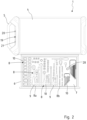
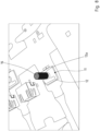
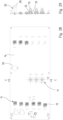
- the Figure 1 shows a tool provision device in the form of a workshop trolley 1.
- a workshop trolley 1 is used to hold and store tools, for example in assembly or repair shops in the land, air or watercraft industries.
- the workshop trolley 1 has a cabinet or frame-like housing 3 mounted on rollers 2 with a cover plate 4.
- a handle 5 is provided on one narrow side of the workshop trolley 1 or the housing 3, which has a rectangular horizontal cross-section.
- the housing 3 forms the supporting body of the workshop trolley 1.
- a number of containers in the form of drawers 6 are arranged vertically one above the other.
- the drawers 6 can be moved on guides provided on drawer supports in the housing 3.
- Each drawer 6 can be locked in place by a lock in the housing 3.
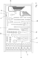
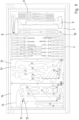
- the workshop trolley 1 with a drawer 6 pulled out of the housing 3 is in the Figure 2 shown.
- a tool carrier 7 is arranged in the drawer 6.
- the tool carrier 7 is formed by a soft foam insert.
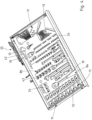
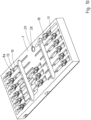
- receptacles 8 are provided for one tool 9 each (see also Figure 3 , Figures 4 to 6 and Figure 10 ).
- a holder 8 has a recess 10 in the tool carrier 7 adapted to the shape of a specific tool 9. It is also possible to arrange several tool carriers 7 in the drawer 6, which complement each other and cover the bottom of the drawer 6. In this regard, reference is also made to the illustration of the Figure 7 referred to.
- the workshop trolley 1 is equipped with a tool identification and management system. This enables the tool inventory to be monitored and managed automatically.
- the tool identification and management system has a data management unit along with peripheral devices that accepts, processes and outputs data, i.e. carries out the necessary data processing automatically.
- the tool carriers 7 arranged in the drawers 6 each consist of a soft foam system and have a large number of receptacles 8 for different tools 9.
- the receptacles are generally provided with the reference number 8.
- the individual receptacles 8, 8a, 8b are each formed by a recess 10 in the tool carrier 7 that is adapted to the shape of a specific tool 9.
- the recesses 10 are formed by depressions in the soft foam inserts of the tool carriers 7.
- Each receptacle 8, 8a, 8b is assigned at least one detector 11 that detects the presence of a tool 9 in the receptacle 8, 8a, 8b.
- the detector 11 has a pushbutton switch 12 with a pushbutton element 13 in the form of a spring-loaded plunger 13a.
- the pushbutton switches 12 are each attached to a circuit board 14 below the receptacles 8, 8a, 8b ( Figure 7 and Figure 10 ), which are arranged on the bottom of the drawers 6 below the tool carriers 7. In this way, the pushbuttons 12 are supported indirectly on the bottom of a drawer 6.
- the pushbutton element 13 of the pushbutton switch 12 passes through an opening 15 in the tool carrier 7.
- the opening 15 is an opening passing through the wall of the tool carrier 7 below a receptacle 8a and is circular in cross-section.
- the diameter of the opening 15 is dimensioned such that a pushbutton element 13 or the plunger 13a can be guided in the opening 15. and can be easily moved back and forth.
- the plunger 13 has a length which is greater than the wall thickness of the tool carrier 7 below the receptacle 8a, so that the plunger 13a projects with an active surface 16 through the base 42 of a receptacle 8a into the receptacle 8a.
- the active surface 16 is formed on the front side of the probe element of the plunger or is formed by the front side of the plunger 13a.
- the probe element 13 or the plunger 13a projects with its front side or with the active surface 16 opposite the base surface of a recess 10.
- Each tool carrier 7 has several receptacles 8a and 8b, each of which is assigned at least one detector 11. All detectors 11 are arranged in a horizontal plane and form a keypad.
- the circuit boards 14 are supports for the pushbuttons 12 and serve for their mechanical fastening and electrical connection. For this purpose, the circuit boards 14 are equipped with corresponding conductive connections and conductor tracks.
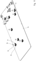
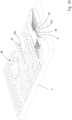
- circuit boards 14 To facilitate the allocation of the tool carriers 7 and the installation of the circuit boards 14 in a drawer 6 as well as the allocation of the tool carriers 7, the outlines 17 of the respective tools 9 are shown on the circuit boards 14. This can be seen in particular in the representations of the Figure 4 and 7 . It can also be seen that several circuit boards 14 are arranged next to one another on the bottom of the drawer 6. Each circuit board 14 has a module size adapted to the dimensions of the drawer 6, so that the circuit boards 14 together cover the bottom area. The individual circuit boards 14 are electrically connected to one another. The connection to the data processing unit is established via interfaces using electrical connecting lines. Cable support devices 25 are arranged in the housing 3 for electrical connecting lines, in particular for the connecting line between the circuit boards 14 and the data processing unit.
- a cable support device 25 is in the Figures 4 to 6
- the cable support device 25 has two support arms 26, 27 connected to one another by a hinged joint. Electrical connecting cables are held and guided via the cable support device 25 so that they can follow the movement without interference when a drawer 6 is pulled out and pushed in.
- the touch element 13 of the touch switches 12 protrude with their active surfaces 16 from the base 42 of a recess 10 so that they protrude into a receptacle 8a of the first type.
- a tool 9 inserted into a receptacle 8a pushes the plunger 13a of a touch switch 12 downwards. This generates a signal and detects the presence of the tool 9 in the respective receptacle 8a of the first type.
- the weight of a tool 9 located in the receptacle 8a pushes the plunger 13 of the touch switch 12 down and activates it.
- When a tool 9 is removed the touch element 13 is relieved.
- the connection to the touch switch 12 is interrupted. This signal detects that a tool 9 has been removed from a receptacle 8 and is missing.
- the touch switches 12 are therefore activated or deactivated by the direct contact of the touch element 13 with a tool 9.
- Holder elements 18 can be designed as clamp-like holder elements.
- a holder element 18 has a spring clip with spring legs arranged in a receptacle 8.
- Such a holder element 18 is particularly suitable in the Figure 7 to be recognized.
- a tool 9 must be inserted into a holder 8 using a certain amount of force to overcome the spring force of the holder element 18. This pressure causes the associated pushbutton switch 12 to be actuated by the contact of the tool 9.
- the holder element 18 holds the tool 9 reliably in the holder 8 and ensures that the pushbutton switch 12 remains in the release position. This is advantageous for lighter tools 9, so that they are held in the holders 8 even when subjected to a shock, for example when transporting the workshop trolley 1.
- a magnetically acting magnet holder element is designed as a permanent magnet and is placed in, below or to the side of a holder 8. The magnetic force of the magnet holder element draws a tool 9 into a holder 8 and increases the pressure against a pushbutton switch 12 and fixes the tool 9 in a holder 8.
- the opening 15 is a breakthrough that penetrates the wall of the tool carrier 7 below a receptacle 8a.
- the touch element 13 of the push button switch 2 which is designed as a plunger 13a, passes through the opening 15 from below through the base 42 of the receptacle 8a and protrudes with its front active surface 16 opposite the base surface of a recess 10 and projects into the receptacle 8a.
- the opening 15 is provided laterally in a side wall 43 of the receptacle 8b.
- the detector 11 has a touch element 13 in the form of a lever 13b, which passes through the opening 15 in the tool carrier 7, the opening 15 being arranged laterally of the receptacle 8b.
- a button 12 has a button element 13 in the form of an articulated lever 13b or spring leg.
- the button element 13 in the form of the lever 13b interacts with a spring-loaded pin 23 of the pushbutton switch 12.
- the opening 15 is designed as a breakthrough which penetrates the side wall 43 of the tool carrier 7 to the side of the holder 8b.
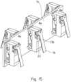
- pushbutton switches 12 as in the Figure 12 shown are also in the Figures 13 to 16 to recognize.
- the Figures 13 and 14 show several pushbutton switches 12 arranged in a row which are arranged in a support body 24 or are accommodated in the support body 24.
- pushbutton switches 12 with pushbutton elements 13 in the form of plungers 13a as shown in the Figures 7 , 8 , 10 and in particular 11.
- the pushbutton switches 12 are assigned to a circuit board 14 and placed in the support body 24.
- the pushbutton switches 12 are placed in the drawer 6 with the support body 24 and the tool carrier 7 is placed on top.
- the components are arranged in such a way that the pushbutton switches 12 with the touch elements 13 protrude into the receptacles 8, 8a, 8b.
- FIG. 17 This can be seen in the representation of the Figure 17 in the left image plane.
- the right image plane of Figure 17 shows a tool 9 inserted into a holder 8b.
- the tool 9 activates the touch elements 13 and the pushbuttons 12 arranged there.
- the touch element 13 of the push button 12 is thereby actuated and the detector 11 is activated. This generates a signal and processes it accordingly.
- the system recognizes that the slot is occupied and the tool 9 is present.
- the touch element 13, 13b on the push button 12 moves back again and the signal becomes negative, which means that a tool 9 is missing.
- the data processing unit of the tool identification and management system of the workshop trolley 1 receives the signals from the detectors 11 and detects the presence or absence of a tool 9 in a holder 8 or 8a, 8b.
- Tool usage data as well as tool status data and/or tool user data can also be recorded using the data processing unit.
- Tool inventory as well as information on maintenance and the condition of the tools and the users are recorded and archived and can be shown on a display that communicates wirelessly or wired with the data processing unit.
- the workshop trolley 1 is also equipped with a locking system by means of which the drawers 6 in the housing 3 can be centrally locked.
- a component of the data processing unit is functional electronics that control at least one actuator. This is used in particular to operate a locking bar of the locking system.
- the functional electronics can also have a wireless communication module, in particular Bluetooth or WLAN.
- a functional area 19 is provided, protected by the handle 5.
- An interface 20 for an identification element, for example an RFID sensor, is arranged there, by means of which the locking system of the workshop trolley 1 can be opened and closed.
- an emergency release with a Cylinder lock 21 is arranged, via which the locking system can be unlocked manually and mechanically if necessary.
- the workshop trolley 1 has an electrical energy supply unit 48. This includes a rechargeable battery 22, which is arranged in a replaceable manner on a housing wall of the workshop trolley 1.
- the workshop trolley 1 is equipped with one or more signal elements 28 in the form of light-emitting diodes.
- Such an optical signal element 28 is particularly suitable for Figures 2 , 3 and 10
- a holder 29 for a signal element 28, which can be mounted on a printed circuit board 14, is shown in the illustration of the Figure 23
- Such a holder 29 with the optical signal element 28 in the form of an LED forms a so-called LED dome.
- the signal elements 28 signal the presence or absence of a tool 9 in a drawer or a holder 8 in a tool carrier 7.
- signal elements 28 in the form of control lamps on a display and in particular in the functional area 19 of a workshop trolley 1.
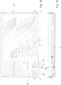
- FIGS. 18 and 19 show a further embodiment of a drawer 6 with an integrated tool carrier 7, which is formed by a soft foam insert.
- Receptacles 8 are provided in the tool carrier 7, each for different tools 9.
- a receptacle 8 has a recess 10 adapted to the shape of a specific tool 9, with integrated detectors 11, via which the presence of a tool 9 in the receptacle 8 is detected.
- a detector 11 with a push button 12 and a push button element 13 is also shown in the illustration of the Figure 19
- the pushbutton element 13 is arranged in a housing 31, which acts as a support body for the pushbutton switch 12 and in particular guides the pushbutton element 13, mechanically protects it and ensures its mobility and smooth operation.
- Holder elements 18 are arranged in various receptacles 8 in the form of magnetic holder elements or magnet holders.
- the magnet holders act as pressure amplifiers within the receptacles 8.
- Tools 9 made of ferromagnetic materials are drawn into the receptacle 8 by magnetic force and an associated pushbutton switch 12 is actuated by contact with the tools 9.
- a pushbutton switch 12 with a pushbutton element 13 arranged in a housing 31 acting as a support body is shown in the illustrations of the Figures 25 and 26 .
- a printed circuit board 14 equipped with pushbutton switches 12 and pushbutton elements 13 integrated in a housing 31 is also shown in the illustrations of the Figures 28 and 29 There you can also see the LED dome 35 with a signal element 28 held in a holder 29.
- a special design of a holder element 18 with magnetic holder elements is shown in the illustration of the Figure 24 There, a total of three magnets 33 are arranged in series in magnet receptacles 34 in a holder body 32.
- the detector 11 has an electrical connector interface 36 for receiving an electrical plug element 37.
- the plug element 37 is the USB plug of a USB cable.
- the pushbutton element 13 To facilitate the actuation of the pushbutton element 13, it has a slanted front surface 38.
- the USB plug When the USB plug is inserted, it comes into contact with the front surface 38 and presses the spring-loaded pushbutton element 13 of the pushbutton switch 12 downwards and actuates it.
- the Figure 31 shows the arrangement before inserting the USB plug into the connector interface 36 of the push button switch 12.
- the Figure 32 shows the arrangement in the connector interface 36 with the plug element 37 inserted.
- the feeler elements 13 have front sides 39 with a semi-circular surface contour 40.
- the surface contour 40 is matched to the outer contour of a tool 9, in the case shown an offset screwdriver.
- the surface contour 40 matched to the tools 9 makes it easier to feel the position of the tools 9.
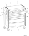
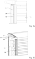
- FIG. 33 A workshop trolley 1 is shown in a closed state in a perspective view.
- the Figures 34 and 35 show sections of the workshop trolley 1 according to the illustration of Figure 33 .
- the workshop trolley 1 is constructed as previously described. Reference is made to the above description.
- a signal element 28 is arranged in an edge protection element 44 provided on the housing 3.
- the housing 3 of the material trolley 1 is equipped with an edge protection element 44 on all four vertical side edges of the housing 3.
- the edge protection elements 44 act as impact and ram protection and are made of an elastic plastic material.
- the edge protection elements 44 primarily have a protective function.
- signal elements 28 are arranged in the edge protection element 44 on the left in the image plane on the front side of the trolley or housing.
- Recesses 45 are provided in the edge protection element 44 to accommodate the signal elements 28.
- the upper end of the recesses 45 is essentially at the same height as the upper edges of a drawer 6, namely at the same height as the drawer handles.
- the integration of the signal elements 28 into the lateral edge protection element 44 on the front side of the housing is functionally advantageous because the signal elements 28 are clearly visible adjacent to the drawer level and are also protected by the edge protection element 44.
- a display 46 is arranged laterally in the area of the cover plate 4, protected by the handle 5. Furthermore, a signal unit 47 is provided, which is set up and intended to signal the closed state of the workshop trolley 1 and the battery charge state of an electrical energy supply unit 48, in particular a rechargeable battery and/or the completeness of the tool inventory in the workshop trolley 1.
- FIG. 36 to 38 a drawer 6 with integrated tool carrier 7 is shown again in a top view or in sectional views corresponding to those AA and DD.
- the design corresponds to the type previously explained. Reference is made to the corresponding designs and component names.
- the Figure 37 shows a tool carrier 7, formed from a soft foam insert, with receptacles 8a of the first type. Recesses 10 adapted to the shape of a specific tool 9 are formed in the tool carrier 7.
- the opening 15 is a breakthrough that penetrates the wall of the tool carrier 7 below a receptacle 8a.
- the probe element 13 with its plunger 13a is guided through the base 42 of the receptacle 8a and protrudes with its active surface 16 into the receptacle 8a.
- the Figure 39 shows again a tool carrier 7 with holders 8a of the first type and holders 8b of the second type.
- the Figure 40 shows a section through the representation of the Figure 39 along the line AA. Based on the enlarged view in Figure 41 A second type of recording 8b is explained again.
- the opening 15 is arranged to the side of the receptacle 8b in its side wall 43.
- a detector 11 has a pushbutton switch 12 with a spring-loaded lateral pushbutton element 13 in the form of a lever 13b. The lever 13b passes through the opening 15 and projects laterally into the receptacle 8b.
- the pushbutton switch 12 is arranged on a vertically oriented circuit board 14. This is held by a support body 24.
- the support body 24 is part of the tool carrier 7 or supplements the tool carrier 7.
- the pushbutton element 13 in the form of the spring-loaded lever 13b protrudes through the side opening 15.
- the lever 13b protrudes laterally with its active surface 16 opposite the opening 15 and protrudes into the holder 8b.
- the lever 13 is articulated on the pushbutton switch 12 and is supported on the pushbutton switch via the spring-loaded pin 23.
- the pushbutton element 13 in the form of the lever 13b is pressed sideways in the direction of the pushbutton switch 12.
- the movement of the lever 13b is transmitted to the pushbutton switch 12 via the pin 23.
- a signal is generated and the presence of the tool 9 in the second type of holder 8b is detected.
Landscapes
- Engineering & Computer Science (AREA)
- Physics & Mathematics (AREA)
- Mechanical Engineering (AREA)
- Mathematical Physics (AREA)
- Theoretical Computer Science (AREA)
- General Physics & Mathematics (AREA)
- Chemical & Material Sciences (AREA)
- Combustion & Propulsion (AREA)
- Transportation (AREA)
- Workshop Equipment, Work Benches, Supports, Or Storage Means (AREA)
Claims (24)
- Dispositif de fourniture d'outils, en particulier chariot d'atelier, établi ou armoire à outils, qui présente un boîtier (3) et des récipients (6), en particulier des tiroirs, disposés dans celui-ci, dans lequel au moins un porte-outils (7) est prévu dans un récipient (6) qui présente plusieurs logements (8) pour des outils (9) et respectivement un détecteur (11) est associé aux logements (8 ; 8a, 8b) pour détecter la présence d'un outil (9) dans le logement (8 ; 8a, 8b),
dans lequel le détecteur (11) présente un commutateur à bouton-poussoir (12) avec un élément de bouton-poussoir (13, 13a, 13b), dans lequel l'élément de bouton-poussoir (13, 13a, 13b) traverse une ouverture (15) dans le porte-outils (7) et pénètre avec une surface active (16) dans le logement (8 ; 8a, 8b), dans lequel, dans le cas d'au moins un logement (8a) de premier type, l'ouverture (15) est une percée traversant la paroi du porte-outils (7) sous le logement (8a) et l'élément de bouton-poussoir (13, 13a) pénètre par le bas à travers le fond (42) d'un logement (8a) de premier type et dans lequel un élément de support (18) est disposé dans au moins un logement (8 ; 8a, 8b), élément qui fait office d'amplificateur de pression pour un outil (7), caractérisé en ce que, dans le cas d'au moins un logement (8b) de second type, l'élément de bouton-poussoir (13, 13b) pénètre latéralement dans le logement (8b) de second type. - Dispositif de fourniture d'outils selon la revendication 1, caractérisé en ce que l'élément de bouton-poussoir (13) est un poussoir (13a), en particulier un poussoir à ressort, une branche, en particulier une branche de ressort ou un levier (13b), en particulier un levier à ressort.
- Dispositif de fourniture d'outils selon la revendication 1 ou 2, caractérisé en ce que le commutateur à bouton-poussoir (12) est disposé dans un corps de support (24).
- Dispositif de fourniture d'outils selon l'une quelconque des revendications 1 à 3, caractérisé en ce que le commutateur à bouton-poussoir (12) ou un corps de support (24) recevant le commutateur à bouton-poussoir (12) s'appuie au moins indirectement sur le fond du récipient (6).
- Dispositif de fourniture d'outils selon l'une quelconque des revendications 1 à 4, caractérisé en ce que le commutateur à bouton-poussoir (12) est fixé sur une carte de circuit imprimé (14) qui est disposée sur le fond du récipient (6) sous le porte-outils (7).
- Dispositif de fourniture d'outils selon l'une quelconque des revendications 1 à 5, caractérisé en ce qu'un détecteur (11) est associé à chaque logement (8), dans lequel tous les détecteurs (11) sont disposés dans un plan horizontal.
- Dispositif de fourniture d'outils selon l'une quelconque des revendications 1 à 6, caractérisé en ce qu'un logement (8) présente un évidement (10) dans le porte-outils (7) adapté à la forme d'un outil spécifique.
- Dispositif de fourniture d'outils selon l'une quelconque des revendications 1 à 7, caractérisé en ce que l'élément de support (18) est un élément de support en forme de pince ou un support magnétique.
- Dispositif de fourniture d'outils selon l'une quelconque des revendications 1 à 8, caractérisé en ce qu'une unité de traitement de données est prévue, qui est destinée à et conçue pour recevoir des signaux du ou des détecteurs (11) et pour enregistrer et documenter un retrait et un retour d'un outil.
- Dispositif de fourniture d'outils selon la revendication 9, caractérisé en ce que des données d'utilisation d'outil et/ou des données d'état d'outil et/ou des données d'utilisateur d'outil peuvent être enregistrées au moyen de l'unité de traitement de données.
- Dispositif de fourniture d'outils selon l'une quelconque des revendications 1 à 10, caractérisé en ce que le porte-outils (7) est formé par un insert en mousse souple.
- Dispositif de fourniture d'outils selon l'une quelconque des revendications 5 à 11, caractérisé en ce que le pourtour (17) d'un ou de plusieurs outils (9) est représenté sur la carte de circuit imprimé (14).
- Dispositif de fourniture d'outils selon l'une quelconque des revendications 5 à 12, caractérisé en ce que plusieurs cartes de circuit imprimé (14) sont disposées côte à côte sur le fond du récipient (6).
- Dispositif de fourniture d'outils selon la revendication 13, caractérisé en ce que chaque carte de circuit imprimé (14) comporte une dimension modulaire adaptée aux dimensions du récipient (6), de sorte que les cartes de circuit imprimé (14) couvrent ensemble la surface de fond.
- Dispositif de fourniture d'outils selon l'une quelconque des revendications 1 à 14, caractérisé en ce qu'au moins un dispositif de support de câble (25) est disposé dans le boîtier (3) pour des lignes de connexion électriques, en particulier pour des lignes de connexion électriques entre des cartes de circuit imprimé (14) dans un récipient (6) et/ou entre des cartes de circuit imprimé (14) et une unité de traitement de données.
- Dispositif de fourniture d'outils selon l'une quelconque des revendications 1 à 15, caractérisé en ce qu'un système de verrouillage est prévu au moyen duquel les récipients (6) sont verrouillables de manière centralisée dans le boîtier (3).
- Dispositif de fourniture d'outils selon l'une quelconque des revendications 1 à 16, caractérisé en ce qu'une électronique de fonctionnement est prévue, dans lequel l'électronique de fonctionnement commande au moins un actionneur, en particulier pour actionner une barre de verrouillage et/ou en ce que l'électronique de fonctionnement présente un module de communication sans fil, en particulier Bluetooth ou WLAN.
- Dispositif de fourniture d'outils selon l'une quelconque des revendications 1 à 17, caractérisé en ce qu'un écran communiquant avec une unité de traitement de données est prévu pour afficher la présence et/ou l'absence d'outils et/ou de données d'utilisation d'outil et/ou de données d'utilisateur.
- Dispositif de fourniture d'outils selon l'une quelconque des revendications 1 à 18, caractérisé en ce qu'au moins un élément de signal (28) est prévu, en particulier un élément de signal optique, de préférence sous forme d'une diode électroluminescente (LED), ou un élément de signal acoustique qui est destiné à et conçu pour signaler la présence ou l'absence d'un outil (9) dans un récipient (6).
- Dispositif de fourniture d'outils selon la revendication 19, caractérisé en ce que l'élément de signal (28) est disposé dans un élément de protection de bord (44) prévu sur le boîtier (3).
- Dispositif de fourniture d'outils selon l'une quelconque des revendications 1 à 20, caractérisé en ce qu'un élément de signal (28) est prévu dans un récipient (6) et/ou une face avant (30) d'un récipient (6) et/ou sur un écran.
- Dispositif de fourniture d'outils selon l'une quelconque des revendications 1 à 21, caractérisé en ce qu'au moins une unité de signal (47) est prévue, qui est configurée et destinée à signaler l'état de fermeture du dispositif de fourniture d'outils et/ou l'état de charge de batterie d'une unité d'alimentation électrique (48) et/ou l'intégralité d'un stock d'outils, dans lequel l'unité de signal (47) est prévue en particulier au niveau d'une zone de poignée ou une zone fonctionnelle (19) sur le boîtier (3).
- Dispositif de fourniture d'outils selon l'une quelconque des revendications 1 à 22, caractérisé en ce qu'au moins un détecteur (11) présente une interface de connecteur électrique (36) pour recevoir un élément de connexion électrique (37), en particulier un connecteur d'un accouplement de ligne mobile.
- Dispositif de fourniture d'outils selon l'une quelconque des revendications 1 à 23, caractérisé en ce qu'au moins un récipient (6), en particulier un tiroir, est équipé d'un système de pesée qui est couplé à une évaluation de poids.
Priority Applications (4)
| Application Number | Priority Date | Filing Date | Title |
|---|---|---|---|
| EP22193176.9A EP4331776B1 (fr) | 2022-08-31 | 2022-08-31 | Dispositif de fourniture d'outils |
| US19/107,026 US20260001215A1 (en) | 2022-08-31 | 2023-07-14 | Tool supply device |
| PCT/EP2023/069667 WO2024046646A1 (fr) | 2022-08-31 | 2023-07-14 | Dispositif de fourniture d'outil |
| CN202380062481.6A CN119789932B (zh) | 2022-08-31 | 2023-07-14 | 工具提供装置 |
Applications Claiming Priority (1)
| Application Number | Priority Date | Filing Date | Title |
|---|---|---|---|
| EP22193176.9A EP4331776B1 (fr) | 2022-08-31 | 2022-08-31 | Dispositif de fourniture d'outils |
Publications (2)
| Publication Number | Publication Date |
|---|---|
| EP4331776A1 EP4331776A1 (fr) | 2024-03-06 |
| EP4331776B1 true EP4331776B1 (fr) | 2024-10-02 |
Family
ID=83152110
Family Applications (1)
| Application Number | Title | Priority Date | Filing Date |
|---|---|---|---|
| EP22193176.9A Active EP4331776B1 (fr) | 2022-08-31 | 2022-08-31 | Dispositif de fourniture d'outils |
Country Status (4)
| Country | Link |
|---|---|
| US (1) | US20260001215A1 (fr) |
| EP (1) | EP4331776B1 (fr) |
| CN (1) | CN119789932B (fr) |
| WO (1) | WO2024046646A1 (fr) |
Family Cites Families (28)
| Publication number | Priority date | Publication date | Assignee | Title |
|---|---|---|---|---|
| CA2226798C (fr) * | 1997-01-14 | 2003-03-18 | Maxtech Manufacturing Inc. | Presentoir d'outils antivol |
| US6707381B1 (en) | 2001-06-26 | 2004-03-16 | Key-Trak, Inc. | Object tracking method and system with object identification and verification |
| US6859854B2 (en) * | 2001-07-25 | 2005-02-22 | Bill Kwong | Universal storage interface bus |
| CA2494904C (fr) * | 2002-08-07 | 2012-01-31 | Supplypro, Inc. | Appareil de securisation de contenus dans des tiroirs |
| WO2005028165A1 (fr) | 2003-09-17 | 2005-03-31 | Coplan Limited | Systeme de controle d'inventaire |
| US7337963B2 (en) * | 2004-04-23 | 2008-03-04 | Winware, Inc. | Portal system for a controlled space |
| GB2451769B (en) * | 2005-02-01 | 2009-12-09 | Intelliject Llc | Devices, systems, and methods for medicament delivery |
| EP1808275A3 (fr) | 2006-01-11 | 2009-10-21 | Gedore-Werkzeugfabrik Otto Dowidat KG | Rangement d'outils |
| DE102007017207A1 (de) | 2006-08-17 | 2008-02-21 | Kb Knecht Gmbh | Vorrichtung zur Erfassung von Werkzeugen in einer Aufbewahrungseinrichtung |
| GB0716108D0 (en) * | 2007-08-17 | 2007-09-26 | Zeroshift Ltd | Inventory control system |
| GB0716085D0 (en) | 2007-08-17 | 2007-09-26 | Zeroshift Ltd | Inventory control system |
| DE102008031372A1 (de) | 2008-07-04 | 2010-01-07 | Gedore-Werkzeugfabrik Otto Dowidat Kg | Überwachung des Vorhandenseins eines Handwerkzeugs |
| US8842183B2 (en) | 2008-08-08 | 2014-09-23 | Snap-On Incorporated | Image-based inventory control system with automatic calibration and image correction |
| CN106408237A (zh) * | 2008-08-08 | 2017-02-15 | 实耐宝公司 | 基于图像的库存控制系统 |
| DE102009047084A1 (de) * | 2009-11-24 | 2011-05-26 | Albertus Magnus Maucher | System zum Zuordnen von Werkzeugen an einer Werkzeug-Halte-Vorrichtung |
| GB2480322B (en) * | 2010-05-14 | 2013-04-24 | Tool Control Systems Ltd | Inventory storage apparatus and inventory item verification process |
| SG191085A1 (en) * | 2010-12-08 | 2013-07-31 | Apex Ind Technologies Llc | Direct access dispensing system |
| US9349113B2 (en) * | 2013-03-26 | 2016-05-24 | 3 Strike, Llc | Storage container with inventory control |
| AT13969U1 (de) | 2013-10-23 | 2015-02-15 | Metallbau Sonnleitner E U | Ausgabeeinrichtung |
| US9358680B1 (en) * | 2014-09-15 | 2016-06-07 | Howard T. Krueger | Wall-mounted tool organizer |
| DE102014019241B4 (de) * | 2014-12-19 | 2018-02-08 | Audi Ag | Eingabeeinrichtung zum Ermitteln einer manuellen Betätigung |
| DE102015120000A1 (de) * | 2015-11-18 | 2017-05-18 | Würth Elektronik Ics Gmbh & Co. Kg | Sensorbaugruppe, Sensorsystem und Lagervorrichtung |
| EP3519132A4 (fr) * | 2016-09-29 | 2020-06-10 | Stanley Industrial & Automotive, LLC | Système de détection d'outils à de multiples emplacements |
| US20200323377A1 (en) * | 2019-03-11 | 2020-10-15 | Daniel J O'CONNOR | Delivery Parcel Locking Device |
| DE102019006380A1 (de) * | 2019-09-10 | 2021-03-11 | SW-Stahl GmbH | Aufbewahrungseinheit für Werkzeuge |
| TWI795725B (zh) * | 2020-02-20 | 2023-03-11 | 林秀貞 | 智能儲物系統及其智能儲物方法 |
| DE102020117787B4 (de) * | 2020-07-06 | 2025-05-15 | Hoffmann Engineering Services GmbH | Aufnahmevorrichtung und Werkergegenstanderkennungsverfahren |
| US11762500B1 (en) * | 2022-05-20 | 2023-09-19 | Apple Inc. | Proximity detection for touch input devices |
-
2022
- 2022-08-31 EP EP22193176.9A patent/EP4331776B1/fr active Active
-
2023
- 2023-07-14 WO PCT/EP2023/069667 patent/WO2024046646A1/fr not_active Ceased
- 2023-07-14 CN CN202380062481.6A patent/CN119789932B/zh active Active
- 2023-07-14 US US19/107,026 patent/US20260001215A1/en active Pending
Also Published As
| Publication number | Publication date |
|---|---|
| CN119789932B (zh) | 2025-12-05 |
| EP4331776A1 (fr) | 2024-03-06 |
| WO2024046646A1 (fr) | 2024-03-07 |
| US20260001215A1 (en) | 2026-01-01 |
| CN119789932A (zh) | 2025-04-08 |
Similar Documents
| Publication | Publication Date | Title |
|---|---|---|
| EP0224802B1 (fr) | Dispositif de planification | |
| DE60112415T2 (de) | Verfahren und gerät zum überwachen einer einrichtung | |
| EP4331776B1 (fr) | Dispositif de fourniture d'outils | |
| EP3606686B1 (fr) | Procédé de fabrication de plaques d'immatriculation de véhicules à moteur en ayant recours à une plaque d'immatriculation, qui est pourvue d'une légende de symboles individuelle estampée | |
| EP2629280B1 (fr) | Système d'apprentissage pour la vérification et le tri de différentes pièces usinées | |
| EP2464204A1 (fr) | Procédé d'émission d'informations sur des appareils d'appareils intégrés dans une armoire électrique | |
| EP1648768A2 (fr) | Siege comportant une memoire de donnees, en particulier siege pour passager aerien, et lecteur correspondant | |
| DE202014011110U1 (de) | Handzange | |
| DE19844797C2 (de) | Fertigungs- und/oder Montagevorrichtung | |
| DE19510303A1 (de) | Vorrichtungen zur Aufnahme von Prüf- und Auswertesensorik | |
| EP3474245B1 (fr) | Système compacteur et procédé de fonctionnement d'un système compacteur | |
| EP3657986B1 (fr) | Unité de stockage | |
| EP3555354B1 (fr) | Dispositif et procédé de manipulation de débris d'une aiguille cassée | |
| DE102007001722A1 (de) | Transportvorrichtung, Zuführungsvorrichtung, Entnahmevorrichtung und Vorrichtung zum Aufnehmen, Transportieren und Sortieren von elektronischen Bauelementen | |
| DE102009041820B4 (de) | Vorrichtung zur Lagerung und Ausgabe von Objekten | |
| DE3751158T2 (de) | System zur Anwesenheitsprüfung von Artikeln in frei zugänglichen Verkaufsapparaten. | |
| DE20220141U1 (de) | Warenbehälter | |
| DE102019112220A1 (de) | Elektronische Schlosseinheit als Ausziehsperre für Schubladen und dergleichen | |
| DE102015000443B4 (de) | Anordnung zur Erkennung der Anwesenheit von Werkzeugen/Instrumenten in einer zugehörigen Sammelablage | |
| DE112018000925B4 (de) | Hilfsvorrichtung für eine elektrische Schutzvorrichtung und elektrische Anordnung mit dieser Hilfsvorrichtung | |
| EP1191328A2 (fr) | Système de commande pour un appareil de test par rayons X | |
| DE102010019944B4 (de) | Schaltschrank | |
| AT408880B (de) | Anordnung zum bereitstellen von teilen | |
| EP4035840A1 (fr) | Dispositif de stockage du moyen de production doté d'un dispositif de transfert d'énergie pour au moins un tiroir | |
| DE102009042565A1 (de) | Signalgesteuerter Arbeitsplatz, Funktionsmodul für einen signalgesteuerten Arbeitsplatz und Produktionsverfahren an einem signalgesteuerten Arbeitsplatz |
Legal Events
| Date | Code | Title | Description |
|---|---|---|---|
| PUAI | Public reference made under article 153(3) epc to a published international application that has entered the european phase |
Free format text: ORIGINAL CODE: 0009012 |
|
| STAA | Information on the status of an ep patent application or granted ep patent |
Free format text: STATUS: REQUEST FOR EXAMINATION WAS MADE |
|
| 17P | Request for examination filed |
Effective date: 20230207 |
|
| AK | Designated contracting states |
Kind code of ref document: A1 Designated state(s): AL AT BE BG CH CY CZ DE DK EE ES FI FR GB GR HR HU IE IS IT LI LT LU LV MC MK MT NL NO PL PT RO RS SE SI SK SM TR |
|
| GRAP | Despatch of communication of intention to grant a patent |
Free format text: ORIGINAL CODE: EPIDOSNIGR1 |
|
| STAA | Information on the status of an ep patent application or granted ep patent |
Free format text: STATUS: GRANT OF PATENT IS INTENDED |
|
| INTG | Intention to grant announced |
Effective date: 20240611 |
|
| GRAS | Grant fee paid |
Free format text: ORIGINAL CODE: EPIDOSNIGR3 |
|
| GRAA | (expected) grant |
Free format text: ORIGINAL CODE: 0009210 |
|
| STAA | Information on the status of an ep patent application or granted ep patent |
Free format text: STATUS: THE PATENT HAS BEEN GRANTED |
|
| AK | Designated contracting states |
Kind code of ref document: B1 Designated state(s): AL AT BE BG CH CY CZ DE DK EE ES FI FR GB GR HR HU IE IS IT LI LT LU LV MC MK MT NL NO PL PT RO RS SE SI SK SM TR |
|
| REG | Reference to a national code |
Ref country code: GB Ref legal event code: FG4D Free format text: NOT ENGLISH |
|
| REG | Reference to a national code |
Ref country code: CH Ref legal event code: EP |
|
| REG | Reference to a national code |
Ref country code: DE Ref legal event code: R096 Ref document number: 502022001802 Country of ref document: DE |
|
| REG | Reference to a national code |
Ref country code: IE Ref legal event code: FG4D Free format text: LANGUAGE OF EP DOCUMENT: GERMAN |
|
| REG | Reference to a national code |
Ref country code: LT Ref legal event code: MG9D |
|
| REG | Reference to a national code |
Ref country code: NL Ref legal event code: MP Effective date: 20241002 |
|
| PG25 | Lapsed in a contracting state [announced via postgrant information from national office to epo] |
Ref country code: NL Free format text: LAPSE BECAUSE OF FAILURE TO SUBMIT A TRANSLATION OF THE DESCRIPTION OR TO PAY THE FEE WITHIN THE PRESCRIBED TIME-LIMIT Effective date: 20241002 |
|
| PG25 | Lapsed in a contracting state [announced via postgrant information from national office to epo] |
Ref country code: NL Free format text: LAPSE BECAUSE OF FAILURE TO SUBMIT A TRANSLATION OF THE DESCRIPTION OR TO PAY THE FEE WITHIN THE PRESCRIBED TIME-LIMIT Effective date: 20241002 |
|
| PG25 | Lapsed in a contracting state [announced via postgrant information from national office to epo] |
Ref country code: IS Free format text: LAPSE BECAUSE OF FAILURE TO SUBMIT A TRANSLATION OF THE DESCRIPTION OR TO PAY THE FEE WITHIN THE PRESCRIBED TIME-LIMIT Effective date: 20250202 Ref country code: HR Free format text: LAPSE BECAUSE OF FAILURE TO SUBMIT A TRANSLATION OF THE DESCRIPTION OR TO PAY THE FEE WITHIN THE PRESCRIBED TIME-LIMIT Effective date: 20241002 Ref country code: PT Free format text: LAPSE BECAUSE OF FAILURE TO SUBMIT A TRANSLATION OF THE DESCRIPTION OR TO PAY THE FEE WITHIN THE PRESCRIBED TIME-LIMIT Effective date: 20250203 |
|
| PG25 | Lapsed in a contracting state [announced via postgrant information from national office to epo] |
Ref country code: FI Free format text: LAPSE BECAUSE OF FAILURE TO SUBMIT A TRANSLATION OF THE DESCRIPTION OR TO PAY THE FEE WITHIN THE PRESCRIBED TIME-LIMIT Effective date: 20241002 |
|
| PG25 | Lapsed in a contracting state [announced via postgrant information from national office to epo] |
Ref country code: BG Free format text: LAPSE BECAUSE OF FAILURE TO SUBMIT A TRANSLATION OF THE DESCRIPTION OR TO PAY THE FEE WITHIN THE PRESCRIBED TIME-LIMIT Effective date: 20241002 |
|
| PG25 | Lapsed in a contracting state [announced via postgrant information from national office to epo] |
Ref country code: ES Free format text: LAPSE BECAUSE OF FAILURE TO SUBMIT A TRANSLATION OF THE DESCRIPTION OR TO PAY THE FEE WITHIN THE PRESCRIBED TIME-LIMIT Effective date: 20241002 |
|
| PG25 | Lapsed in a contracting state [announced via postgrant information from national office to epo] |
Ref country code: NO Free format text: LAPSE BECAUSE OF FAILURE TO SUBMIT A TRANSLATION OF THE DESCRIPTION OR TO PAY THE FEE WITHIN THE PRESCRIBED TIME-LIMIT Effective date: 20250102 |
|
| PG25 | Lapsed in a contracting state [announced via postgrant information from national office to epo] |
Ref country code: GR Free format text: LAPSE BECAUSE OF FAILURE TO SUBMIT A TRANSLATION OF THE DESCRIPTION OR TO PAY THE FEE WITHIN THE PRESCRIBED TIME-LIMIT Effective date: 20250103 Ref country code: LV Free format text: LAPSE BECAUSE OF FAILURE TO SUBMIT A TRANSLATION OF THE DESCRIPTION OR TO PAY THE FEE WITHIN THE PRESCRIBED TIME-LIMIT Effective date: 20241002 |
|
| PG25 | Lapsed in a contracting state [announced via postgrant information from national office to epo] |
Ref country code: CZ Free format text: LAPSE BECAUSE OF FAILURE TO SUBMIT A TRANSLATION OF THE DESCRIPTION OR TO PAY THE FEE WITHIN THE PRESCRIBED TIME-LIMIT Effective date: 20241002 Ref country code: PL Free format text: LAPSE BECAUSE OF FAILURE TO SUBMIT A TRANSLATION OF THE DESCRIPTION OR TO PAY THE FEE WITHIN THE PRESCRIBED TIME-LIMIT Effective date: 20241002 |
|
| PG25 | Lapsed in a contracting state [announced via postgrant information from national office to epo] |
Ref country code: RS Free format text: LAPSE BECAUSE OF FAILURE TO SUBMIT A TRANSLATION OF THE DESCRIPTION OR TO PAY THE FEE WITHIN THE PRESCRIBED TIME-LIMIT Effective date: 20250102 |
|
| PG25 | Lapsed in a contracting state [announced via postgrant information from national office to epo] |
Ref country code: SM Free format text: LAPSE BECAUSE OF FAILURE TO SUBMIT A TRANSLATION OF THE DESCRIPTION OR TO PAY THE FEE WITHIN THE PRESCRIBED TIME-LIMIT Effective date: 20241002 |
|
| REG | Reference to a national code |
Ref country code: DE Ref legal event code: R097 Ref document number: 502022001802 Country of ref document: DE |
|
| PG25 | Lapsed in a contracting state [announced via postgrant information from national office to epo] |
Ref country code: DK Free format text: LAPSE BECAUSE OF FAILURE TO SUBMIT A TRANSLATION OF THE DESCRIPTION OR TO PAY THE FEE WITHIN THE PRESCRIBED TIME-LIMIT Effective date: 20241002 |
|
| PG25 | Lapsed in a contracting state [announced via postgrant information from national office to epo] |
Ref country code: EE Free format text: LAPSE BECAUSE OF FAILURE TO SUBMIT A TRANSLATION OF THE DESCRIPTION OR TO PAY THE FEE WITHIN THE PRESCRIBED TIME-LIMIT Effective date: 20241002 |
|
| PG25 | Lapsed in a contracting state [announced via postgrant information from national office to epo] |
Ref country code: RO Free format text: LAPSE BECAUSE OF FAILURE TO SUBMIT A TRANSLATION OF THE DESCRIPTION OR TO PAY THE FEE WITHIN THE PRESCRIBED TIME-LIMIT Effective date: 20241002 |
|
| PG25 | Lapsed in a contracting state [announced via postgrant information from national office to epo] |
Ref country code: SK Free format text: LAPSE BECAUSE OF FAILURE TO SUBMIT A TRANSLATION OF THE DESCRIPTION OR TO PAY THE FEE WITHIN THE PRESCRIBED TIME-LIMIT Effective date: 20241002 |
|
| PG25 | Lapsed in a contracting state [announced via postgrant information from national office to epo] |
Ref country code: IT Free format text: LAPSE BECAUSE OF FAILURE TO SUBMIT A TRANSLATION OF THE DESCRIPTION OR TO PAY THE FEE WITHIN THE PRESCRIBED TIME-LIMIT Effective date: 20241002 |
|
| PLBE | No opposition filed within time limit |
Free format text: ORIGINAL CODE: 0009261 |
|
| STAA | Information on the status of an ep patent application or granted ep patent |
Free format text: STATUS: NO OPPOSITION FILED WITHIN TIME LIMIT |
|
| PG25 | Lapsed in a contracting state [announced via postgrant information from national office to epo] |
Ref country code: SE Free format text: LAPSE BECAUSE OF FAILURE TO SUBMIT A TRANSLATION OF THE DESCRIPTION OR TO PAY THE FEE WITHIN THE PRESCRIBED TIME-LIMIT Effective date: 20241002 |
|
| 26N | No opposition filed |
Effective date: 20250703 |
|
| PGFP | Annual fee paid to national office [announced via postgrant information from national office to epo] |
Ref country code: DE Payment date: 20250826 Year of fee payment: 4 |
|
| PGFP | Annual fee paid to national office [announced via postgrant information from national office to epo] |
Ref country code: FR Payment date: 20250828 Year of fee payment: 4 |
|
| REG | Reference to a national code |
Ref country code: CH Ref legal event code: H13 Free format text: ST27 STATUS EVENT CODE: U-0-0-H10-H13 (AS PROVIDED BY THE NATIONAL OFFICE) Effective date: 20260324 |
|
| PG25 | Lapsed in a contracting state [announced via postgrant information from national office to epo] |
Ref country code: MC Free format text: LAPSE BECAUSE OF FAILURE TO SUBMIT A TRANSLATION OF THE DESCRIPTION OR TO PAY THE FEE WITHIN THE PRESCRIBED TIME-LIMIT Effective date: 20241002 |
|
| PG25 | Lapsed in a contracting state [announced via postgrant information from national office to epo] |
Ref country code: LU Free format text: LAPSE BECAUSE OF NON-PAYMENT OF DUE FEES Effective date: 20250831 |
|
| PG25 | Lapsed in a contracting state [announced via postgrant information from national office to epo] |
Ref country code: CH Free format text: LAPSE BECAUSE OF NON-PAYMENT OF DUE FEES Effective date: 20250831 |