EP4331787A2 - Signalgenerator auf basis von induktanzeigenschaften eines elements, elektrisches scherwerkzeug und scheröffnungsgradsteuerungsverfahren für ein elektrisches scherwerkzeug - Google Patents
Signalgenerator auf basis von induktanzeigenschaften eines elements, elektrisches scherwerkzeug und scheröffnungsgradsteuerungsverfahren für ein elektrisches scherwerkzeug Download PDFInfo
- Publication number
- EP4331787A2 EP4331787A2 EP23193445.6A EP23193445A EP4331787A2 EP 4331787 A2 EP4331787 A2 EP 4331787A2 EP 23193445 A EP23193445 A EP 23193445A EP 4331787 A2 EP4331787 A2 EP 4331787A2
- Authority
- EP
- European Patent Office
- Prior art keywords
- inductance
- magnetizer
- blade
- opening degree
- air core
- Prior art date
- Legal status (The legal status is an assumption and is not a legal conclusion. Google has not performed a legal analysis and makes no representation as to the accuracy of the status listed.)
- Pending
Links
Images






Classifications
-
- B—PERFORMING OPERATIONS; TRANSPORTING
- B26—HAND CUTTING TOOLS; CUTTING; SEVERING
- B26B—HAND-HELD CUTTING TOOLS NOT OTHERWISE PROVIDED FOR
- B26B15/00—Hand-held shears with motor-driven blades
-
- A—HUMAN NECESSITIES
- A01—AGRICULTURE; FORESTRY; ANIMAL HUSBANDRY; HUNTING; TRAPPING; FISHING
- A01G—HORTICULTURE; CULTIVATION OF VEGETABLES, FLOWERS, RICE, FRUIT, VINES, HOPS OR SEAWEED; FORESTRY; WATERING
- A01G3/00—Cutting implements specially adapted for horticultural purposes; Delimbing standing trees
- A01G3/02—Secateurs; Flower or fruit shears
- A01G3/033—Secateurs; Flower or fruit shears having motor-driven blades
- A01G3/037—Secateurs; Flower or fruit shears having motor-driven blades the driving means being an electric motor
Definitions
- the present disclosure relates to the technical field of electric shearing tools, and particularly to, a signal generator based on inductance characteristics of element, an electric shearing tool, and a shear opening degree control method for an electric shearing tool.
- a position of a blade of an existing pruning shear is mainly controlled using a Hall element induction magnet based on a Hall effect.
- the working principle is as follows:
- the Hall effect is essentially a deflection caused by the Lorentz force acting on a moving charged particle in a magnetic field.
- the charged particle an electron or a hole
- this deflection leads to accumulation of positive and negative charges in a direction perpendicular to a current and the magnetic field, thereby forming an additional transverse electric field which is referred to as the Hall electric field.
- a distance between a trigger magnet and a Hall element can be determined by detecting a magnitude of an electromotive force of an electric field using a modern technology, thereby associating a trigger of a pruning shear with a position of a blade and achieving control of the position of the blade of the pruning shear.
- a linear Hall effect IC responds proportionally to a magnetic flux density. As shown in FIG. 7 , it is assumed that a signal output range of a linear Hall element is 0 V to Vout. When there is no magnetic field, an analog output drive 1 ⁇ 2 is Vout. Induction of north and south magnetic poles generates a unique voltage. Therefore, after the type of a linear Hall element is selected, it is necessary to confirm an S pole or an N pole of a magnet during mounting. Therefore, the existing electric pruning shear that use the Hall element induction magnet to control the position of the blade is not convenient to mount, and a control portion of the existing electric pruning shear needs to be improved.
- MCU micro control unit
- the present disclosure aims to provide a technical solution capable of addressing the aforementioned issues.
- a signal generator based on inductance characteristics of an element includes a signal generator mounted on an electric tool; the signal generator includes a base plate, a manual actuator, an air core inductor, and a magnetizer; the manual actuator is movably connected to the base plate; fixed portions are arranged on both the manual actuator and the base plate; the two fixed portions moves relatively close to each other or away from each other through movement of the manual actuator; the air core inductor and the magnetizer are respectively connected to the two fixed portions; and the magnetizer is plugged along a middle portion of the air core inductor or is separated along the middle portion of the air core inductor through the movement of the two fixed portions close to each other or away from each other.
- the manual actuator is manually driven to move on the basis of a position movably connected to the base plate, so that the fixed portion on the manual actuator acts, and the two fixed portions move close to each other or away from each other through the movement of the manual actuator.
- the air core inductor and the magnetizer are respectively connected to the two fixed portions, so that the magnetizer is plugged along the middle portion of the air core inductor or is separated along the middle portion of the air core inductor when the two fixed portions move close to each other or away from each other.
- the manual actuator is pulled and released, the whole magnetizer is correspondingly plugged into and separated from the air core inductor.
- the magnetic conductivity of a magnetizer material of the air core inductor is changed, thereby changing an inductance value of the air core inductor. That is, the air core inductor and the magnetizer are separately mounted, and the objective of changing the inductance value of the air core inductor can be achieved by changes in a relative distance between the magnetizer and the air core inductor, and the inductance value is changed linearly.
- a shear opening degree control method for an electric shearing tool includes:
- An electric shearing tool includes a main body of the electric shearing tool; the main body of the electric shearing tool is provided with:
- the present disclosure has the following beneficial effects.
- a changeable inductance value of the inductance type transducer is obtained by changing the relative position between the triggering member and the inductance type transducer.
- the control processor can obtain the current relative position information between the triggering member and the inductance type transducer after judging the inductance value, thereby mapping the relative position information position to the positions of the blades; and the positions of the blades echo the blade travel control member.
- the control processor can precisely obtain relative position information between the triggering member and the inductance type transducer according to linear changes of the inductance value, thereby obtaining position information of the blade travel control member. Each position point can be mapped to current positions of the blades. Furthermore, since the inductance type transducer and the triggering member are used for control and detection, the following problem can be avoided during mounting: the production efficiency is affected because an S pole or an N pole of a magnet needs to be confirmed during mounting after the type of an existing linear Hall element is selected. The mounting convenience is better.
- the embodiments of the present disclosure are achieved using an inductor to induct a magnetizer 40.
- a structure of the inductor is generally composed of a framework, a winding, a shielding cover, a packaging material, and the magnetizer 40.
- the present disclosure changes an inductance value on the basis of a relative position between the magnetizer 40 and a coil. When the magnetizer 40 is completely separated from the coil, air serves as a medium of the magnetizer 40. When the magnetizer 40 is slowly plugged into a gap in the middle of the coil, the inductance value also changes as the magnetizer 40 moves.
- the magnetizer 40 is fixed on a trigger of a pruning shear according to the drawings, and the coil is also fixed at a corresponding reasonable position.
- the present disclosure adopts a signal generator based on inductance characteristics of an element, including a signal generator mounted on an electric tool.
- the signal generator includes a base plate 10, a manual actuator 20, an air core inductor 30, and a magnetizer 40;
- the manual actuator 20 is movably connected to the base plate 10; fixed portions are arranged on both the manual actuator 20 and the base plate 10; the two fixed portions moves relatively close to each other or away from each other through movement of the manual actuator 20; the air core inductor 30 and the magnetizer 40 are respectively connected to the two fixed portions; and the magnetizer 40 is plugged along a middle portion of the air core inductor 30 or is separated along the middle portion of the air core inductor 30 through the movement of the two fixed portions close to each other or away from each other.
- the manual actuator 20 is manually driven to move on the basis of a position movably connected to the base plate 10.
- the manual actuator 20 includes a moving component 21 and a connector 22; the moving component 21 is movably connected to the base plate 10 through the connector 22; and the fixed portion of the manual actuator 20 is arranged on the moving component 21, so that the fixed portion on the manual actuator 20 acts, and the two fixed portions move close to each other or away from each other through the movement of the manual actuator 20.
- the movement of the manual actuator 20 is usually achieved by manual pulling, twisting, pressing, pulling, and the like.
- the base plate 10 carries a first reset spring 11 abutted with the moving component 21.
- the moving component 21 is reset through the first reset spring 11.
- the air core inductor 30 and the magnetizer 40 are respectively connected to the two fixed portions, so that the magnetizer 40 is plugged along the middle portion of the air core inductor 30 or is separated along the middle portion of the air core inductor 30 when the two fixed portions move close to each other or away from each other.
- the relative position between the magnetizer 40 and the air core inductor 30 is changed to change the inductance value.
- FIG. 1 to FIG. 2 show a first embodiment and a second embodiment of the signal generator in the present disclosure.
- the moving component 21 can move in a manner of being rotatably connected to the base plate 10.
- the connector 22 is fixed on the base plate 10; the connector 22 is provided with a rotating shaft structure 23; the moving component 21 rotates around the rotating shaft structure 23; the air core inductor 30 and the magnetizer 40 can be respectively arranged on the moving component 21 and the base plate 10; and the air core inductor 30 and the magnetizer 40 can also be respectively arranged on the base plate 10 and the moving component 21. They are arranged according to an actual need.
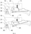
- FIG. 3 shows a third embodiment of the signal generator in the present disclosure. Due to the arrangement of this structure, a movement trajectory of the fixed portion is an arc when the moving component 21 moves. As a result, the magnetizer 40 cannot be plugged along a center of the air core inductor 30 or cannot be separated along the center of the air core inductor 30. Therefore, the air core inductor 30 can be fixedly connected to the fixed portion of the base plate 10, and the magnetizer 40 is in drive connection to the fixed portion of the moving component 21.
- a guide sleeve 12 is arranged on the base plate 10; the magnetizer 40 is in guide connection to the guide sleeve 12; and the magnetizer 40 is plugged along the center of the air core inductor 30 or is separated along the center of the air core inductor 30 through the guide sleeve 12.
- a moving direction of the magnetizer 40 can be restrained.
- the magnetizer 40 and the moving component 21 are in drive connection. If a resisting pushing manner is used, a second reset spring 41 abutted with the guide sleeve 12 needs to be arranged on the magnetizer 40; and the magnetizer 40 is reset through the second reset spring 41.
- the fixed portion is arranged at one end of the moving component 21.
- a middle portion of the moving component 21 is in running fit with a rotating shaft structure 23, and the other end of the moving component 21 is used as a manual actuation end, so that the manual actuator 20 is manually pulled to act.
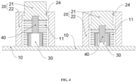
- FIG. 4 to FIG. 5 show a fourth embodiment and a fifth embodiment of the signal generator in the present disclosure.
- the moving component 21 can move in a manner of being slidably connected to the base plate 10.
- the connector 22 is fixed on the base plate 10.
- the connector 22 is provided with a guide hole structure 24.
- the moving component 21 is slidably connected to the guide hole structure 24.
- An upper end of the moving component 21 is used as a manual actuation end.
- the fixed portion is arranged at a lower end of the moving component.
- the air core inductor 30 and the magnetizer 40 can be respectively arranged on the moving component 21 and the base plate 10, and the air core inductor 30 and the magnetizer 40 can also be respectively arranged on the base plate 10 and the moving component 21.
- the electric tool used in the present disclosure may be a pair of electric scissors, a pair of electric pliers, an electric saw, and the like, which includes the abovementioned signal generator based on the inductance characteristics of the element, and further includes a main body 3.
- a working head 1 is arranged at a front end of the main body 3.
- a circuit control unit 2 is arranged in the main body 3.
- the signal generator is mounted on the main body 3.
- the signal generator and the working head 1 are both electrically connected to the circuit control unit 2.
- the signal generator is in fixed fit with the main body 3 through the base plate 10, or the base plate 10 is directly integrally formed with the main body 3, so that the air core inductor 30 is arranged in the main body 3, and the magnetizer 40 is arranged at one end of the manual actuator 20.
- the other end of the manual actuator 20 is used as a manual actuation end and is exposed out of the main body 3.
- a middle portion of the manual actuator 20 is movably connected to the main body 3.
- a pair of electric scissors is taken as an example.
- the working head 1 of the electric scissors is an electric scissors head.
- the circuit control unit 2 of the electric scissors is electrically connected to an air core inductor 30, and a magnetizer 40 is mounted on the manual actuator 20 of the electric scissors.
- the manual actuator 20 of the electric scissors is usually of a trigger structure. When the manual actuator 20 is in a released state, the magnetizer 40 is separated from the air core inductor 30.
- the magnetizer 40 When the manual actuator 20 is repeatedly actuated, the magnetizer 40 may be correspondingly plugged into the air core inductor 30 and cannot move. A moving speed of the magnetizer 40 in the air core inductor 30 is related to related actions of pulling and releasing the manual actuator 20.
- the whole magnetizer 40 is correspondingly plugged into and separated from the air core inductor 30.
- the magnetic conductivity of a magnetizer material of the air core inductor 30 is changed, thereby changing the inductance value of the air core inductor 30.
- the inductance value is changed linearly.
- the air core inductor 30 and the magnetizer 40 are separately mounted.
- the objective of changing the inductance value of the air core inductor 30 can be achieved by changes in a relative distance between the magnetizer 40 and the air core inductor 30.
- a micro control unit MCU
- the MCU successfully detects the change of the inductance value through the corresponding signal conditioning circuit, so that a current operation movement range of the manual actuator 20 is perfectly determined.
- the MCU can perfectly detect the relative distance between the magnetizer 40 and the air core inductor 30.
- Each distance point can be mapped to current positions of blades of the electric scissors, so that the positions of the blades of the electric scissors correspond to the position of the manual actuator 20, and the blades can move at will.
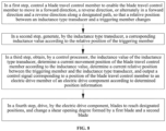
- the shear opening degree control method includes:
- a changeable inductance value of the inductance type transducer is obtained by changing the relative position between the triggering member and the inductance type transducer.
- the control processor can obtain the current relative position information between the triggering member and the inductance type transducer after judging the inductance value, thereby mapping the relative position information position to the positions of the blades; and the positions of the blades echo the blade travel control member.
- the control processor can precisely obtain relative position information between the triggering member and the inductance type transducer according to linear changes of the inductance value, thereby obtaining position information of the blade travel control member. Each position point can be mapped to current positions of the blades. Furthermore, since the inductance type transducer and the triggering member are used for control and detection, the following problem can be avoided during mounting: the production efficiency is affected because an S pole or an N pole of a magnet needs to be confirmed during mounting after the type of an existing linear Hall element is selected. The mounting convenience is better.
- control processor obtains the inductance value of the inductance type transducer in real time.
- the following electric shearing tool can be innovatively obtained on the basis of the above shear opening degree control method, or it can be understood that the above shear opening degree control method is innovatively obtained on the basis of the following electric shearing tool.
- the electric shearing tool is set as follows:
- An electric shearing tool includes an electric shearing tool main body 101.
- the electric shearing tool main body 101 is provided with:
- the electric shearing tool main body is further provided with a speed changer (not shown).
- the blade travel control member corresponds to an output end of the speed changer.
- a user manipulator is arranged at an input end of the speed changer.
- the speed changer correspondingly causes the blade travel control member to move due to mechanical drive.
- a response (such as enlarging a movement range or reducing a movement range) of the blade travel control member is changed by the speed changer, so that it is easier for the user to control the shear opening degree to a desired opening degree.
- An electric drive member of the electric drive component 104 is usually a motor. Power is output through the motor. Clockwise and counterclockwise rotations of the motor can finally cause the corresponding blade to move in a forward direction and a reverse direction.
- the motor can only drive one blade, or can drive the two blades at the same time. When the motor drives the blade, the power output by the motor can finally reach the blade through a gearbox 111, so as to change a torque, a speed, or a direction.
- the electric drive component 104 only drives one blade, for example, when the blade driven is the first blade 102, the first blade 102 is correspondingly a movable blade, and the second blade 103 is correspondingly a fixed blade.
- the second blade 103 is mounted on the electric shearing tool main body 101.
- the first blade 102 can be driven by the electric drive component 104 in a rotating manner.
- the first blade is rotatably arranged on the electric shearing tool main body through a rotating shaft, or the first blade rotatably sleeves a rotating shaft of the electric shearing tool main body, or the first blade is connected to a power output shaft.
- the power output shaft can be an output shaft of the motor or an output shaft of the gearbox.
- the electric drive member of the electric drive component 104 can also be an electric push rod, a cylinder, a hydraulic cylinder, an electric main shaft, or the like, which has a forward and reverse drive function.
- the inductance type transducer 107 can adopt a commonly used variable-clearance inductance transducer, a variable-area inductance transducer, or a solenoid insert type inductance transducer.
- the blade travel control member 105 can be moved in the following ways: pressing, for example, it is a button with a reset function; pushing, for example, it is a sliding sleeve or a sliding push rod; rotating, for example it is a trigger, a knob, a rotatable grip, and the like.
- a specific movement way of the blade travel control member of the electric shearing tool and a specific setting of the inductance type transducer can be randomly matched in the above listed solutions and in accordance with directly obtained similar solutions.
- An embodiment of the electric shearing tool after the matching can be as shown in FIG. 9 to FIG. 10 .
- the blade travel control member is a trigger 501 rotatably arranged on the electric shearing tool main body 101.
- the inductance type transducer is a toroidal air core inductor or an inductance coil 701 mounted on the electric shearing tool main body 101.
- the triggering member is a magnetizer 601 mounted on the trigger. When the trigger 501 rotates, the magnetizer 601 is in a moving state of being plugged into the toroidal air core inductor or the inductance coil 701, or the magnetizer 601 is in a moving state of being separated from the toroidal air core inductor or the inductance coil 701.
- the magnetizer 601 When the trigger 501 is pulled, the magnetizer 601 is driven by the rotating trigger 501, so that a relative position between the magnetizer 601 and the toroidal air core inductor or the inductance coil 701 changes, and an inductance value generated by the toroidal air core inductor or the inductance coil 701 changes.
- the control processor 108 obtains the inductance value generated by the toroidal air core inductor or the inductance coil 701, determines a current rotating position of the trigger 501 according to the inductance value, determines a relative position between the magnetizer 601 and the toroidal air core inductor or the inductance coil 701, and outputs, according to the determined position information, a control signal corresponding to the position of the blade travel control member to the electric drive member of the electric drive component 104 (namely, drive the blade to the corresponding position), thereby adjusting a shear opening degree 100 formed by the first blade 102 and the second blade 103 to a corresponding opening degree.
- the change of the relative position between the magnetizer 601 and the toroidal air core inductor or the inductance coil 701 is as follows:
- the foregoing action that the blade travel control member moves according to the designated path can be understood as follows:
- the trigger 501 rotates by taking the electric shearing tool main body 101 as a support.
- the forward direction may be a rotating direction of the trigger when the trigger is pulled.
- the magnetizer is preferably a magnetic core, or a metal piece with high magnetic conductivity, such as iron, nickel, and manganese.
- the electric shearing tool is also provided with an elastic member 109.
- the elastic member 109 corresponds to the trigger 501.
- the elastic member 109 undergoes elastic deformation through a force exerted by the trigger 501.
- the elastic member 109 recovers from the elastic deformation and drives the trigger 501 to be automatically reset.
- the elastic member can use an elastic object such as a pressure spring, a tension spring, a torsion spring, and a clip.
- the mounting position of the magnetizer 601 and the mounting position of the toroidal air core inductor or the inductance coil 701 are interchangeable, that is, the magnetizer 601 is mounted on the electric shearing tool main body 101, and the toroidal air core inductor or the inductance coil 701 is mounted on the trigger 501.
- the control processor 108 in order to enable the control processor 108 to obtain the inductance value information of the toroidal air core inductor or the inductance coil 701, the control processor (MCU) is provided with a signal conditioning circuit.
- the signal conditioning circuit includes a second-order integration circuit, a detection circuit, and an operational amplifier.
- the second-order integration circuit is configured to convert square waves into sine waves, and positive and negative amplitude values of the sine wave vary as the inductance value of the inductance type transducer changes.
- the detection circuit is configured to convert the sine wave converted by the second-order integration circuit into a relatively stable direct-current voltage.
- the operational amplifier is configured to amplify the direct-current voltage obtained by the detection circuit and finally input the direct-current voltage to the control processor (MCU) for sampling and analog-digital conversion, and the control processor (MCU) more accurately determines the relative position between the magnetizer and the toroidal air core inductor or the inductance coil.
- Waveform changes can be seen in FIG. 12 , it should be noted that the waveform changes shown in FIG. 12 should be understood as an example, and the waveform can correspondingly change as a frequency, amplitude, and other data changes.
- the second-order integration circuit includes a resistive load R2, a resistive load R8, and a capacitive load C5.
- the detection circuit includes a diode D2, a resistive load R7, and a capacitive load C4.
- the resistive load R2, the resistive load R8, and the capacitive load C5 cooperate with the toroidal air core inductor or the inductance coil (J1 in FIG.
- the control processor is provided with an oscillation circuit that is matched with the toroidal air core inductor or the inductance coil.
- the inductance value generated by the toroidal air core inductor or the inductance coil according to the relative position of the magnetizer is correspondingly converted into the oscillation frequency, and the oscillation frequency is correspondingly changed by changing a displacement of the magnetizer.
- a frequency within a specific detection frequency band is output in response to a specific displacement of the magnetizer with a specific magnetic conductivity; and the control processor correspondingly controls and outputs a shear opening degree corresponding to the frequency after receiving the frequency within the specific detection frequency band.
- the inductance value is mainly determined by the magnetic conductivity of the magnetizer, the cross-sectional area of the magnetizer, and a depth of the magnetizer entering the coil. That is, when a distance of the magnetizer with a specific cross-sectional area and specific magnetic conductivity in the coil is a value (namely, the above specific displacement) within a specific range, the inductance value generated is a specific inductance value, and the specific inductance value is converted by the oscillation circuit into the frequency within the specific detection frequency band.
- the magnetizer can use a cylindrical Ni-Zn ferrite with a diameter of 3 mm.
- the electric shearing tool works in a very complex environment. For example, when a fragment with the same magnetic conductivity and a different cross-sectional area accidentally falls into the coil, or a fragment with the same cross-sectional area and different magnetic conductivity accidentally falls into the coil, injury or loss is easily caused once the electric shearing tool is triggered for shearing by mistake. Therefore, to control the shear opening degree of the electric shearing tool, particularly the shear opening degree of an electric shearing tool for pruning, a control system for the electric shearing tool is required to be able to reliably and stably identify whether there is a triggering member enters, so as to reduce injury or loss.
- the shear opening degree is correspondingly controlled only when the control processor obtains the frequency within the specific detection frequency band, which eliminates the influence of a frequency outside the specific detection frequency band on the control of the shear opening degree and effectively improves the reliability and stability of the control of the shear opening degree.
- the setting of the above specific detection frequency and the control performed by the control processor on the specific detection frequency improve the reliability and stability of the control.
- the coil, the magnetizer, the oscillation circuit, the control processor, and other hardware no additional hardware needs to be added for control, and only a control program is correspondingly set, which is more conductive to reducing the cost.
- information of all frequency points of the specific detection frequency band is pre-stored in a memory of the control processor, and each frequency point corresponds to one shear opening degree; after receiving the oscillation frequency, the control processor is configured to: first determine whether the received oscillation frequency is within the specific detection frequency band; and if the oscillation frequency is within the specific detection frequency band, perform comparison to obtain corresponding shear opening degree information, and correspondingly control and output the corresponding shear opening degree. Much further, after receiving the oscillation frequency, the control processor is configured to: if it is determined that the received oscillation frequency is not within the specific detection frequency band, skip correspondingly controlling and outputting a shear opening degree or maintain the current shear opening degree.
- a shear opening degree is not controlled and output, which can indicate that the shear opening degree is recovered to an initial angle.
- the initial angle is set to be a maximum opening degree
- the control processor automatically performs the control. That is, the electric drive component drives the blade to be reset to an initial position, so that the shear opening degree is recovered to the initial maximum angle, which effectively ensures that the blade can be safely and timely withdrawn and reset, improves the safety, effectively avoids secondary injury to a person, and effectively reduces secondary damage to the electric shearing tool.
- the specific detection frequency band is a low frequency band.
- the electric shearing tool for pruning has a relatively high shearing force.
- the specific detection frequency band is set to be the low frequency band, a quantity of pulses after conversion is proper, which counts the specific detection frequency more easily and controls the corresponding shear opening degree more accurately, so that the applicability of the inductance type transducer to controlling the shear opening degree of the electric shearing tool is better.
- the specific detection frequency band is 40 KHz to 55 KHz.
- the shear opening degree gradually decreases, the frequency within the specific detection frequency band gradually decreases. For example, when the obtained frequency is 55 KHz, the shear opening degree is correspondingly controlled to be maximum.
- the above frequency band is the low frequency band.
- a linear ratio of gradually decreasing 55 KHz to 40 KHz is closer to a ratio of the blade.
- the above frequency band has higher applicability when it is applied to controlling the shear opening degree of the electric shearing tool.
- the above specific detection frequency band is more conductive to improving the accuracy of controlling the shear opening degree.
- a static working frequency for representing influence of external debris is set.
- the frequency within the specific detection frequency band is less than the static working frequency.
- an amplitude value of oscillation is a value of a detection point that is greater than 150%, so that the interference resistance is better.
- the specific detection frequency band is 40 KHz to 55 KHz
- the static working frequency is preferably set to be 60 KHz. There is a relatively large safety margin between the specific detection frequency band and the static working frequency.
- common metal debris includes copper, iron, aluminum, contaminant water, sewage, tree leaves, oil, and the like, and their influence frequency bands are all close to the static working frequency.
- the influence of the common debris can be effectively avoided by setting the static working frequency. That is, on the one hand, the setting and use of the above specific detection frequency band and static working frequency can ensure that the inductance type transducer has relatively good applicability and control precision when applied to controlling the shear opening degree of the electric shearing tool; and on the other hand, there is a relatively large safety margin during the setting of the static working frequency.
- An oscillation circuit is preferably as shown in FIG. 15 .
- the resistor R2 is an output current limiting resistor, which is connected to the toroidal air core inductor or the inductance coil (J1) in FIG. 15 .
- a detection point may be point A or point B.
- Point A is a high-potential frequency output point
- point B is a low-potential frequency output point.
- a frequency is controlled in a pulse width modulation (PWM) manner.
- PWM pulse width modulation
- the blade travel control member enables the magnetizer to move in the direction of being separated from the toroidal air core inductor or the inductance coil according to the designated path, and the magnetizer is close to an opening of the toroidal air core inductor or the inductance coil when reaching an end point, and blocks part of the opening; the magnetizer blocks part of the opening to satisfy the following: debris with a cross section greater than or equal to a cross section of the magnetizer is unable to pass through the opening.
- the elastic member drives the trigger to be reset.
- the trigger is reset to correspondingly drive the magnetizer 601 to move in the direction of being separated from the toroidal air core inductor or the inductance coil.
- the magnetizer moves in the direction of being separated from the toroidal air core inductor or the inductance coil, but after the trigger is completely released (after the trigger is completely reset), a gap reserved between the magnetizer and the opening of the toroidal air core inductor or the inductance coil is maintained to be small. The small gap prevents debris with a cross-sectional area larger than or equal to that of the magnetizer from passing.
- a reset position of the trigger can be limited by arranging a corresponding limiting member, so that after the trigger is completely released (after the trigger is completely reset), the gap reserved between the magnetizer and the opening of the toroidal air core inductor or the inductance coil is maintained to be the aforementioned small gap, and the debris with the cross-sectional area larger than or equal to that of the magnetizer cannot pass through the small gap.
- the phenomena of mis-identification and mis-triggering are effectively avoided.
- the trigger has better safety when applied to controlling the shear opening degree of the electric shearing tool.
- the electric shearing tool further includes a power supply module 110.
- the power supply module 110 can be configured to be connected to a mains supply, so as to supply power to the power consumers of the electric shearing tool.
- the power supply module 110 can also be configured to supply power to the power consumers of the electric shearing tool through a built-in storage battery.
- the control processor and the electric drive component can communicate with each other in a wired or wireless manner.
- the wired and wireless communication technologies are common technologies, and will not be described in detail here.
Landscapes
- Life Sciences & Earth Sciences (AREA)
- Forests & Forestry (AREA)
- Engineering & Computer Science (AREA)
- Mechanical Engineering (AREA)
- Scissors And Nippers (AREA)
- Hand Tools For Fitting Together And Separating, Or Other Hand Tools (AREA)
Applications Claiming Priority (3)
| Application Number | Priority Date | Filing Date | Title |
|---|---|---|---|
| CN202222356325.6U CN217986061U (zh) | 2022-09-03 | 2022-09-03 | 一种基于器件电感特性的信号生成件及其电动工具 |
| CN202211074536.9A CN115362841A (zh) | 2022-09-03 | 2022-09-03 | 一种电动剪切工具的剪切开度控制方法 |
| CN202310886484.3A CN116922458B (zh) | 2022-09-03 | 2023-07-19 | 一种电动剪切工具的剪切开度控制方法 |
Publications (2)
| Publication Number | Publication Date |
|---|---|
| EP4331787A2 true EP4331787A2 (de) | 2024-03-06 |
| EP4331787A3 EP4331787A3 (de) | 2024-04-03 |
Family
ID=87845871
Family Applications (1)
| Application Number | Title | Priority Date | Filing Date |
|---|---|---|---|
| EP23193445.6A Pending EP4331787A3 (de) | 2022-09-03 | 2023-08-25 | Signalgenerator auf basis von induktanzeigenschaften eines elements, elektrisches scherwerkzeug und scheröffnungsgradsteuerungsverfahren für ein elektrisches scherwerkzeug |
Country Status (1)
| Country | Link |
|---|---|
| EP (1) | EP4331787A3 (de) |
Family Cites Families (4)
| Publication number | Priority date | Publication date | Assignee | Title |
|---|---|---|---|---|
| FR2957834B1 (fr) * | 2010-03-24 | 2012-03-09 | Infaco | Dispositif de controle positionnel de deux elements l'un par rapport a l'autre tel que lames d'outils de coupe du genre secateur et outil de coupe le comportant |
| US9872440B2 (en) * | 2012-05-04 | 2018-01-23 | Felco Motion Sa | Handheld power tool |
| JP6467314B2 (ja) * | 2015-08-04 | 2019-02-13 | 株式会社マキタ | 電動はさみ |
| CN208133022U (zh) * | 2018-04-23 | 2018-11-23 | 中山绿威科技有限公司 | 电动剪刀机 |
-
2023
- 2023-08-25 EP EP23193445.6A patent/EP4331787A3/de active Pending
Also Published As
| Publication number | Publication date |
|---|---|
| EP4331787A3 (de) | 2024-04-03 |
Similar Documents
| Publication | Publication Date | Title |
|---|---|---|
| CN116922458B (zh) | 一种电动剪切工具的剪切开度控制方法 | |
| US20230403984A1 (en) | Signal generator based on inductance characteristics of element, electric shearing tool, and shear opening degree control method for electric shearing tool | |
| CN107040245B (zh) | 千安培大电流脉冲信号产生装置及didt测试设备 | |
| CN110488140B (zh) | 一种电磁铁故障检测电路装置及其检测方法 | |
| DE10315765A1 (de) | Elektromagnetischer Energiewandler | |
| DE10315764B4 (de) | Elektromagnetischer Energiewandler für miniaturisierte Funkschalter | |
| EP2042792A3 (de) | Magnetventil mit einer Handhilfsbetätigung | |
| EP4331787A2 (de) | Signalgenerator auf basis von induktanzeigenschaften eines elements, elektrisches scherwerkzeug und scheröffnungsgradsteuerungsverfahren für ein elektrisches scherwerkzeug | |
| EP2073343B1 (de) | Sensor | |
| CA2374283A1 (en) | Magnetic flux detector | |
| CN101424724B (zh) | 一种快速精确检测电磁继电器的磁路闭合的方法及其装置 | |
| US20210094156A1 (en) | Power tool with electrically controlled commutating assembly | |
| DE102008046374B3 (de) | Schaltgerät | |
| CN210269477U (zh) | 电磁驱动回弹仪 | |
| EP1705786A3 (de) | Linearstellglied mit Geschwindigkeitsaufnehmer | |
| CN217986061U (zh) | 一种基于器件电感特性的信号生成件及其电动工具 | |
| CN204089637U (zh) | 微电机的驱动电源 | |
| EP1400997A3 (de) | Elektrischer Schalter | |
| CN107658157B (zh) | 用于核电厂设备鉴定测试中旋转操作的可控机电装置 | |
| CN109244914B (zh) | 变电站高压开关柜的地刀压板打开机构 | |
| CN203554329U (zh) | 一种用于稀土超磁致伸缩惯性冲击式微电机的驱动电源 | |
| CN209190695U (zh) | 一种电子装置及电动工具 | |
| JP2007024689A (ja) | 非接触位置検出センサ | |
| CN218584948U (zh) | 一种断路器分合闸线圈特性检测装置 | |
| CN210773849U (zh) | 牵引杆运动轨迹的检测装置 |
Legal Events
| Date | Code | Title | Description |
|---|---|---|---|
| PUAI | Public reference made under article 153(3) epc to a published international application that has entered the european phase |
Free format text: ORIGINAL CODE: 0009012 |
|
| STAA | Information on the status of an ep patent application or granted ep patent |
Free format text: STATUS: REQUEST FOR EXAMINATION WAS MADE |
|
| PUAL | Search report despatched |
Free format text: ORIGINAL CODE: 0009013 |
|
| 17P | Request for examination filed |
Effective date: 20230825 |
|
| AK | Designated contracting states |
Kind code of ref document: A2 Designated state(s): AL AT BE BG CH CY CZ DE DK EE ES FI FR GB GR HR HU IE IS IT LI LT LU LV MC ME MK MT NL NO PL PT RO RS SE SI SK SM TR |
|
| AK | Designated contracting states |
Kind code of ref document: A3 Designated state(s): AL AT BE BG CH CY CZ DE DK EE ES FI FR GB GR HR HU IE IS IT LI LT LU LV MC ME MK MT NL NO PL PT RO RS SE SI SK SM TR |
|
| RIC1 | Information provided on ipc code assigned before grant |
Ipc: A01G 3/06 20060101ALI20240228BHEP Ipc: A01G 3/037 20060101ALI20240228BHEP Ipc: B26B 15/00 20060101AFI20240228BHEP |
|
| STAA | Information on the status of an ep patent application or granted ep patent |
Free format text: STATUS: EXAMINATION IS IN PROGRESS |
|
| 17Q | First examination report despatched |
Effective date: 20250822 |
|
| STAA | Information on the status of an ep patent application or granted ep patent |
Free format text: STATUS: THE APPLICATION IS DEEMED TO BE WITHDRAWN |