EP4331919A1 - Fahrzeugeinstellungsvorrichtung, fahrzeugbordvorrichtung, fahrzeugeinstellungssystem, fahrzeugeinstellungsverfahren und programm - Google Patents
Fahrzeugeinstellungsvorrichtung, fahrzeugbordvorrichtung, fahrzeugeinstellungssystem, fahrzeugeinstellungsverfahren und programm Download PDFInfo
- Publication number
- EP4331919A1 EP4331919A1 EP21944180.5A EP21944180A EP4331919A1 EP 4331919 A1 EP4331919 A1 EP 4331919A1 EP 21944180 A EP21944180 A EP 21944180A EP 4331919 A1 EP4331919 A1 EP 4331919A1
- Authority
- EP
- European Patent Office
- Prior art keywords
- setting
- vehicle
- information
- user identification
- unit
- Prior art date
- Legal status (The legal status is an assumption and is not a legal conclusion. Google has not performed a legal analysis and makes no representation as to the accuracy of the status listed.)
- Pending
Links
Images





Classifications
-
- B—PERFORMING OPERATIONS; TRANSPORTING
- B60—VEHICLES IN GENERAL
- B60R—VEHICLES, VEHICLE FITTINGS, OR VEHICLE PARTS, NOT OTHERWISE PROVIDED FOR
- B60R16/00—Electric or fluid circuits specially adapted for vehicles and not otherwise provided for; Arrangement of elements of electric or fluid circuits specially adapted for vehicles and not otherwise provided for
- B60R16/02—Electric or fluid circuits specially adapted for vehicles and not otherwise provided for; Arrangement of elements of electric or fluid circuits specially adapted for vehicles and not otherwise provided for electric constitutive elements
- B60R16/037—Electric or fluid circuits specially adapted for vehicles and not otherwise provided for; Arrangement of elements of electric or fluid circuits specially adapted for vehicles and not otherwise provided for electric constitutive elements for occupant comfort, e.g. for automatic adjustment of appliances according to personal settings, e.g. seats, mirrors, steering wheel
-
- B—PERFORMING OPERATIONS; TRANSPORTING
- B60—VEHICLES IN GENERAL
- B60W—CONJOINT CONTROL OF VEHICLE SUB-UNITS OF DIFFERENT TYPE OR DIFFERENT FUNCTION; CONTROL SYSTEMS SPECIALLY ADAPTED FOR HYBRID VEHICLES; ROAD VEHICLE DRIVE CONTROL SYSTEMS FOR PURPOSES NOT RELATED TO THE CONTROL OF A PARTICULAR SUB-UNIT
- B60W50/00—Details of control systems for road vehicle drive control not related to the control of a particular sub-unit, e.g. process diagnostic or vehicle driver interfaces
- B60W50/0098—Details of control systems ensuring comfort, safety or stability not otherwise provided for
-
- G—PHYSICS
- G06—COMPUTING OR CALCULATING; COUNTING
- G06F—ELECTRIC DIGITAL DATA PROCESSING
- G06F21/00—Security arrangements for protecting computers, components thereof, programs or data against unauthorised activity
- G06F21/30—Authentication, i.e. establishing the identity or authorisation of security principals
- G06F21/31—User authentication
- G06F21/32—User authentication using biometric data, e.g. fingerprints, iris scans or voiceprints
-
- B—PERFORMING OPERATIONS; TRANSPORTING
- B60—VEHICLES IN GENERAL
- B60W—CONJOINT CONTROL OF VEHICLE SUB-UNITS OF DIFFERENT TYPE OR DIFFERENT FUNCTION; CONTROL SYSTEMS SPECIALLY ADAPTED FOR HYBRID VEHICLES; ROAD VEHICLE DRIVE CONTROL SYSTEMS FOR PURPOSES NOT RELATED TO THE CONTROL OF A PARTICULAR SUB-UNIT
- B60W50/00—Details of control systems for road vehicle drive control not related to the control of a particular sub-unit, e.g. process diagnostic or vehicle driver interfaces
- B60W2050/0062—Adapting control system settings
- B60W2050/0075—Automatic parameter input, automatic initialising or calibrating means
- B60W2050/0083—Setting, resetting, calibration
-
- B—PERFORMING OPERATIONS; TRANSPORTING
- B60—VEHICLES IN GENERAL
- B60W—CONJOINT CONTROL OF VEHICLE SUB-UNITS OF DIFFERENT TYPE OR DIFFERENT FUNCTION; CONTROL SYSTEMS SPECIALLY ADAPTED FOR HYBRID VEHICLES; ROAD VEHICLE DRIVE CONTROL SYSTEMS FOR PURPOSES NOT RELATED TO THE CONTROL OF A PARTICULAR SUB-UNIT
- B60W2540/00—Input parameters relating to occupants
- B60W2540/043—Identity of occupants
Definitions
- the present invention relates to a vehicle setting apparatus, a vehicle onboard apparatus, a vehicle setting system, a vehicle setting method, and a program.
- Patent Document 1 describes the following.
- an in-vehicle environment automatic change apparatus mounted on a vehicle, stores in advance in-vehicle environment information in relation to a mobile phone owned by a user.
- the in-vehicle environment information includes seat position information, air-conditioner setting information, audio setting information, and navigation system setting information.
- the in-vehicle environment automatic change apparatus pairs with a mobile phone when a key is inserted into the vehicle, and performs setting of the in-vehicle environment by using the in-vehicle environment information relating to the paired mobile phone.
- Patent Document 2 describes that onboard equipment mounted on a vehicle transmits operation data of the vehicle and biometric information of a driver to a data center. Further, Patent Document 3 describes that a vehicle control apparatus mounted on a vehicle is remotely operated by an operation apparatus.
- An example object of the present invention is to reduce work for changing a setting of a setting target of the vehicle to a state according to a user's preferred state.
- a vehicle setting apparatus that communicates with a vehicle onboard apparatus mounted on a vehicle, the vehicle setting apparatus including:
- a vehicle onboard apparatus being mounted on a vehicle, the vehicle onboard apparatus including:
- a vehicle setting system including the vehicle setting apparatus described above and the vehicle onboard apparatus described above.
- a vehicle setting method including, by a computer that communicates with a vehicle onboard apparatus mounted on a vehicle:
- a vehicle setting method including, by a computer mounted on a vehicle:
- a program causing a computer that communicates with a vehicle onboard apparatus mounted on a vehicle to have:
- a program causing a computer mounted on a vehicle to have:
- a small amount of workload is required for changing a setting target of a vehicle to a driver's preferred state.
- Fig. 1 is a diagram illustrating a configuration of a vehicle setting system according to the example embodiment.
- the vehicle setting system is a system for setting a state of a setting target of a vehicle 30 for each user.
- the setting target includes at least one of a movable portion such as a position and angle of a driver's seat or a front passenger's seat, an angle of a mirror (for example, a side mirror such as a door mirror), and an operation condition of an air-conditioning system (for example, a setting temperature).
- the vehicle setting system includes a vehicle setting apparatus 10 and a vehicle onboard apparatus 20.
- the vehicle setting apparatus 10 and the vehicle onboard apparatus 20 communicate with each other.
- the vehicle setting system uses information for identifying a user of the vehicle setting system (hereinafter, referred to as user identification information).
- the user identification information preferably includes biometric information.
- the biometric information used here is, for example at least one of face information that is generated from a face image (for example, a feature value of a face) and fingerprint information, but is not limited thereto.
- the user identification information may be configured only by the biometric information.
- the vehicle onboard apparatus 20 is mounted on the vehicle 30.
- the vehicle onboard apparatus 20 acquires user identification information of a person on board of the vehicle 30 and transmits the user identification information to the vehicle setting apparatus 10.
- the vehicle onboard apparatus 20 transmits information indicating a vehicle type of the vehicle 30 (hereinafter, referred to as vehicle type information) to the vehicle setting apparatus 10 as required.
- the vehicle setting apparatus 10 stores setting information for each piece of user identification information.
- the setting information is information for setting the setting target to a predetermined state and is generated for each person.
- the setting information indicates, for example, a preferred state of the person (for example, a position of a seat and an angle of a mirror).
- the vehicle setting apparatus 10 transmits the setting information relating to the user identification information acquired from the vehicle onboard apparatus 20, to the vehicle onboard apparatus 20.
- the vehicle setting apparatus 10 may store the setting information for each piece of vehicle type information and for each piece of user identification information. In this case, the vehicle setting apparatus 10 transmits the setting information relating to a combination of the user identification information and the vehicle type information that are acquired from the vehicle onboard apparatus 20 (an example of a target combination), to the vehicle onboard apparatus 20.
- the vehicle onboard apparatus 20 executes processing of setting the state of the setting target of the vehicle 30 (hereinafter, referred to as setting processing) by using the setting information acquired from the vehicle setting apparatus 10. For example, the vehicle onboard apparatus 20 outputs the setting information to a control apparatus mounted on the vehicle 30. Then, the control apparatus sets the state of the setting target according to the setting information. Note that, the vehicle onboard apparatus 20 and the control apparatus may be wired or wirelessly connected.
- the vehicle 30 may be owned by, for example, an individual or a corporation such as a company.
- the state of the setting target differs according to an owner and each family member, for example.
- the vehicle 30 may be used for rental purposes or car-sharing.
- a suitable state of the setting target (for example, a suitable position of a seat or a suitable angle of a mirror) differs according to a user.
- a different vehicle is prepared each time a rental car or car sharing service is provided, even when the user specifies the same vehicle type.
- the setting target described above can easily be set to a suitable state even when a different vehicle is provided, by using the vehicle setting system illustrated in Fig. 1 .
- Fig. 2 is a diagram illustrating an example of a function configuration of the vehicle setting apparatus 10.
- the vehicle setting apparatus 10 includes a first reception unit 110, an information decision unit 120, a first transmission unit 130, and a first storage unit 140.
- the first storage unit 140 stores the setting information in relation to the user identification information for each of a plurality of persons. When the setting information is generated for each vehicle type, the first storage unit 140 stores the setting information for each piece of user identification information and for each piece of vehicle type information.
- the first reception unit 110 receives user identification information of a user boarding the vehicle, from the vehicle onboard apparatus 20. Herein, the first reception unit 110 also receives the vehicle type information from the vehicle onboard apparatus 20 as required.
- the information decision unit 120 reads out setting information relating to the user identification information received by the first reception unit 110 (hereinafter, referred to as first setting information), from the first storage unit 140.
- first setting information setting information relating to the user identification information received by the first reception unit 110
- the information decision unit 120 reads out the setting information relating to the combination of the user identification information and the vehicle type information that are received by the first reception unit 110, as the first setting information.
- the first transmission unit 130 transmits the first setting information to the vehicle onboard apparatus 20.
- the vehicle setting apparatus 10 further includes a second storage unit 150 and an update unit 160.
- the first storage unit 140 may not store the setting information relating to the user identification information and the vehicle type information that are received by the first reception unit 110.
- the information decision unit 120 generates the first setting information by also using information stored in the second storage unit 150.
- the second storage unit 150 stores information relating to a movable portion of the vehicle type for each vehicle type information (hereinafter, referred to as movable portion information).
- the movable portion information includes information indicating a position or a direction of a movable portion in a standard state.
- the information decision unit 120 reads out setting information (hereinafter, referred to as second setting information) relating to a combination of vehicle type information (hereinafter, referred to as second vehicle type information) that is different from the vehicle type information received by the first reception unit 110 (hereinafter, referred to as first vehicle type information) and the user identification information.
- the information decision unit 120 reads out the movable portion information relating to the first vehicle type information and the movable portion information relating to the second vehicle type information from the second storage unit 150, and generates the first setting information by using those two pieces of the movable portion information and the second setting information. Details of the processing executed herein are described later with reference to another drawing.
- the update unit 160 updates the information stored in the first storage unit 140.
- the first reception unit 110 receives information for generating or updating the setting information (hereinafter, referred to as update information) and the vehicle type information, from the vehicle onboard apparatus 20.
- the update unit 160 updates the information stored in the first storage unit 140 by using the update information and the vehicle type information that are received by the first reception unit 110.
- the update unit 160 causes the first storage unit 140 to store an update date.
- the processing executed by the update unit 160 and detail examples of the update information are described later with reference to another drawing.
- At least one of the first storage unit 140 and the second storage unit 150 may be positioned outside of the vehicle setting apparatus 10.
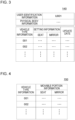
- Fig. 3 is a diagram illustrating an example of the information stored in the first storage unit 140.
- the first storage unit 140 stores the setting information and the update date of the setting information for each combination of the user identification information and the vehicle type information.
- the setting information includes setting information of a seat (for example, at least one of a driver's seat and a front passenger's seat) and setting information of a mirror.
- the setting information of the seat includes information indicating a position of the seat in a front-and-rear direction, a height of the seat, and an angle of a backrest.
- the setting information of the mirror includes information indicating horizontal and vertical angles of the side mirror.
- the first storage unit 140 stores physical body information of a user in relation to the user identification information of the user.
- the physical body information includes information relating to a size of the user's body (for example, at least one of a height and a seated height).
- the information decision unit 120 uses the physical body information at the time of generating the setting information as required. Note that, the first storage unit 140 may not store the physical body information.
- Fig. 4 is a diagram illustrating one example of the information stored in the second storage unit 150.
- the second storage unit 150 stores the movable portion information for each piece of vehicle type information.
- the movable portion information includes information relating to a seat and information relating to a mirror.
- the information relating to the seat includes information indicating a relative position between a driver's seat in a standard state (that is, a set value is 0) and at least one of an acceleration pedal and a brake pedal, a height of the seat in the standard state (with the ground surface as a reference), and information indicating inclination of the backrest of the seat in the standard state.
- the information relating to the mirror includes information relating to a relative angle of the mirror in the standard state with the driver's seat in the standard state as a reference (for example, an angle of the mirror in the standard state with the longitudinal direction of the vehicle 30 as a reference). Detail examples of the movable portion information are described later with reference to another drawing.
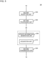
- Fig. 5 is a diagram illustrating one example of a function configuration of the vehicle onboard apparatus 20.
- the vehicle onboard apparatus 20 includes an acquisition unit 210, a second transmission unit 220, a second reception unit 230, and a setting processing unit 240.
- the acquisition unit 210 acquires user identification information of a user boarding the vehicle 30.
- the acquisition unit 210 acquires an image from an image capturing apparatus mounted on the vehicle 30, and generates face information by processing the image.
- the image capturing apparatus may be a part of the acquisition unit 210 or may be outside of the vehicle onboard apparatus 20.
- the acquisition unit 210 includes a sensor for reading fingerprint information.
- the acquisition unit 210 may acquire the user identification information from a mobile terminal owned by a user.
- the second transmission unit 220 transmits the user identification information acquired by the acquisition unit 210 to the vehicle setting apparatus 10. In this state, the second transmission unit 220 also transmits the vehicle type information to the vehicle setting apparatus 10 as required.
- the second transmission unit 220 stores the vehicle type information in advance. Note that, another function unit of the vehicle onboard apparatus 20 may store the vehicle type information.
- the second reception unit 230 receives the setting information from the vehicle setting apparatus 10.
- the setting processing unit 240 executes the setting processing described above, that is, processing of setting the state of the setting target, by using the setting information received by the second reception unit 230.
- the setting information being received is output to the control apparatus of the vehicle 30.
- the setting processing unit 240 may directly control the setting target according to the setting target being received.
- the vehicle onboard apparatus 20 further includes an update information generation unit 250.
- the update information generation unit 250 generates the update information by using the information acquired from the vehicle 30.
- the update information is information for updating the setting information stored in the first storage unit 140 of the vehicle setting apparatus 10.
- the setting processing unit 240 executes the setting processing described above before the vehicle 30 starts moving. However, setting according to the setting processing may not be optimal for a user. Thus, a user may change the setting of the setting target while the vehicle 30 moves.
- the update information generation unit 250 acquires information indicating the state of the setting target in this state (for example, a position of the seat in the front-and-rear direction, a height of the seat, and an angle of the backrest and horizontal and vertical angles of the side mirror), from the vehicle 30, and the information is used as the update information.
- the second transmission unit 220 transmits the update information to the vehicle setting apparatus 10.
- Fig. 6 is a diagram illustrating a hardware configuration example of the vehicle setting apparatus 10.
- the vehicle setting apparatus 10 includes a bus 1010, a processor 1020, a memory 1030, a storage device 1040, an input/output interface 1050, and a network interface 1060
- the bus 1010 is a data transmission path in which the processor 1020, the memory 1030, the storage device 1040, the input/output interface 1050, and the network interface 1060 transmit and receive data mutually. Note that, a method of connecting the processor 1020 and the like to one another is not limited to bus connection.
- the processor 1020 is a processor achieved by a central processing unit (CPU), a graphics processing unit (GPU), or the like.
- CPU central processing unit
- GPU graphics processing unit
- the memory 1030 is a main storage apparatus achieved by a random access memory (RAM) or the like.
- the storage device 1040 is an auxiliary storage apparatus achieved by a hard disk drive (HDD), a solid state drive (SSD), a memory card, a read only memory (ROM), or the like.
- the storage device 1040 stores a program module for achieving each function (for example, the first reception unit 110, the information decision unit 120, the first transmission unit 130, and the update unit 160) of the vehicle setting apparatus 10.
- each function for example, the first reception unit 110, the information decision unit 120, the first transmission unit 130, and the update unit 160
- the storage device 1040 also functions as the first storage unit 140 and the second storage unit 150.
- the input/output interface 1050 is an interface for connecting the vehicle setting apparatus 10 to various input/output devices.
- the network interface 1060 is an interface for connecting the vehicle setting apparatus 10 to a network.
- the network is a local area network (LAN) or a wide area network (WAN), for example.
- a method for connecting the network interface 1060 to the network may be wireless connection or wired connection.
- the vehicle setting apparatus 10 communicates with the vehicle onboard apparatus 20 via the network interface 1060, for example.
- the storage device 1040 stores a program module for achieving each function (for example, the acquisition unit 210, the second transmission unit 220, the second reception unit 230, the setting processing unit 240, and the update information generation unit 250) of the vehicle onboard apparatus 20.
- the vehicle onboard apparatus 20 communicates with the vehicle 30 via the input/output interface 1050, for example.
- the vehicle onboard apparatus 20 communicates with the vehicle setting apparatus 10 via the network interface 1060, for example.
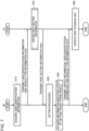
- Fig. 7 is a flowchart illustrating one example of processing that is executed by the vehicle setting apparatus 10 and the vehicle onboard apparatus 20.
- the acquisition unit 210 of the vehicle onboard apparatus 20 acquires user identification information of the user (step S10).
- the image capturing apparatus mounted on the vehicle 30 when the user identification information is face information, the image capturing apparatus mounted on the vehicle 30 generates a face image of a user in the vehicle 30 without any operation by the user.
- the acquisition unit 210 generates face information as the user identification information (for example, a feature value of a face) by processing the face image. In this manner, there is almost no work for the user to do when the acquisition unit 210 acquires the user identification information.
- the image capturing apparatus may generate a face image when the user performs a predetermined operation.
- the second transmission unit 220 transmits the user identification information that is acquired by the acquisition unit 210 and vehicle type information, to the vehicle setting apparatus 10 (step S20).
- the first reception unit 110 of the vehicle setting apparatus 10 receives the user identification information and the vehicle type information that are transmitted by the vehicle onboard apparatus 20.
- the information decision unit 120 decides first setting information to be transmitted to the vehicle onboard apparatus 20 (step S30).
- the first transmission unit 130 transmits the first setting information to the vehicle onboard apparatus 20 (step S40).
- the second reception unit 230 of the vehicle onboard apparatus 20 receives the first setting information from the vehicle setting apparatus 10. Subsequently, the setting processing unit 240 executes the setting processing by using the first setting information received by the second reception unit 230.
- One example of the setting processing is as described with reference to Fig. 1 (step S50). The setting processing is executed before the vehicle 30 starts moving (for example, before a user starts driving the vehicle 30).
- a user changes the state of the setting target as required. For example, a user changes at least one of a position of the seat in the front-and-rear direction, a height of the seat, an angle of the backrest, a horizontal angle of the side mirror, and a vertical angle of the side mirror, as required.
- the update information generation unit 250 acquires information indicating the current state of the setting target (step S60). By using the information, the update information generation unit 250 generates the update information, that is, information for updating the setting information stored in the first storage unit 140.
- the second transmission unit 220 transmits the update information, the user identification information generated in step S10, and the vehicle type information to the vehicle setting apparatus 10 (step S70). Note that, the user identification information being transmitted herein may be generated at this timing.
- step S60 and step S70 when the state indicated by the information acquired in step S60 and the state indicated by the first setting information acquired in step S40 are the same, in other words, when the state of the setting target is not changed after step S50, the processing after step S70 may be omitted. Further, in step S60 or step S70, processing of confirming a user whether to update the first setting information to the information indicating the current setting may be executed.
- One example of the processing is processing of prompting an input (for example, an input to a touch panel) for instructing update (for example, display on a screen or a voice sound output).
- the first reception unit 110 of the vehicle setting apparatus 10 acquires the update information, the user identification information, and the vehicle type information from the vehicle onboard apparatus 20.
- the update unit 160 updates the setting information relating to the combination of the user identification information and the vehicle type information that are acquired by the first reception unit 110 in the first storage unit 140, to information indicated by the update information.
- the first storage unit 140 may not store the setting information relating to the combination of the user identification information and the vehicle type information that are acquired this time.
- the update unit 160 generates new setting information relating to the combination by using the update information and causes the first storage unit 140 to store the new setting information (step S80).
- step S40 when a user uses the vehicle setting apparatus 10 for the first time, the setting information may not be transmitted to the vehicle onboard apparatus 20 in step S40.
- the processing in step S50 is not executed, but the processing in step S60 to step S80 is executed.
- the update unit 160 causes the first storage unit 140 to store the new setting information in relation to the new combination of the user identification information and the vehicle type information.
- Fig. 8 is a flowchart illustrating a detail example of step S30 in Fig. 7 .
- the information decision unit 120 of the vehicle setting apparatus 10 reads out the setting information as the first setting information (step S320).
- the information decision unit 120 confirms whether the setting information relating to the user identification information that is transmitted by the vehicle onboard apparatus 20 and another piece of vehicle type information (second vehicle type information) is stored in the first storage unit 140 (step S330).
- step S330: No When no setting information relating to the user identification information (step S330: No) is stored, the information decision unit 120 does not generate the first setting information. In this case, the first transmission unit 130 transmits the information indicating the situation to the vehicle onboard apparatus 20.
- the information decision unit 120 reads out the setting information, that is, the setting information relative to the second vehicle type information from the first storage unit 140 (step S340).
- the information decision unit 120 may select vehicle type information with the most recent update date of the setting information as the second vehicle type information or may select vehicle type information of a vehicle type having a vehicle shape with the highest similarity to the current vehicle type as the second vehicle type information.
- the information decision unit 120 reads out movable portion information relating to the first vehicle type information and movable portion information relating to the second vehicle type information from the second storage unit 150 (step S350). Subsequently, the information decision unit 120 corrects the setting information acquired in step S340 by using the two pieces of the movable portion information that are read out in step S350, and thus generates the setting information to be transmitted to the vehicle onboard apparatus 20, that is, the first setting information (step S360). Note that, details of the processing executed in step S360 are described later with reference to another drawing.
- Fig. 9 is a diagram illustrating a first example of the processing that is executed by the information decision unit 120 in step S360 in Fig. 8 .
- the information decision unit 120 generates information indicating a position of a driver's seat 32 in the front-and-rear direction, as at least a part of the setting information.
- a vehicle type A is relating to the first vehicle type information
- a vehicle type B is relating to the second vehicle type information.
- the position of the seat 32 in the front-and-rear direction is required to be set in such a way that a distance D from the seat 32 to a pedal 34 (for example, an accelerator pedal or a brake pedal) is a value desired by a user.
- the information decision unit 120 generates the first setting information in such a way that the distance D of the vehicle type B is equal to the distance D acquired according to the setting information of the vehicle type A (hereinafter, referred to as a target distance).
- the movable portion information includes the distance D when the seat 32 is in the standard state (hereinafter, referred to as a standard distance).
- the standard distance may differ according to a vehicle type.
- the setting information includes information indicating an extent to which the seat 32 is deviated from the standard state.
- the information decision unit 120 computes the target distance by using those pieces of information. Further, the information decision unit 120 computes a difference between the target distance and the standard distance of the vehicle type B, and the difference is used as the setting information.
- the setting information may include inclination of a backrest of the seat 32.
- inclination of a backseat in the setting information of the vehicle type A is directly used as inclination of a backseat in the setting information of the vehicle type B.
- the setting information may include a height of the seat 32 with a floor surface in the vehicle as a reference, and in this case, a height of the seat 32 in the setting information of the vehicle type A is directly used as a height of the seat 32 in the setting information of the vehicle type B.
- the position of the seat 32 in the front-and-rear direction, the angle of the backrest, and the height of the seat may be set in a stepwise manner instead of a continuous manner.
- the setting information is information indicating the steps.
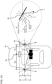
- Fig. 10 is a diagram illustrating a second example of the processing that is executed by the information decision unit 120 in step S360 in Fig. 8 .
- the information decision unit 120 generates information indicating a horizontal angle of a side mirror 36, as at least a part of the setting information.
- an angle Y 1 when a visual line of a user seated on the seat 32 is reflected by the side mirror 36 (a reference is the longitudinal direction of the vehicle, however the width direction of the vehicle may be used) is required to be a value desired by the user.
- the information decision unit 120 generates the first setting information relating to the side mirror 36 in such a way that the angle Y 1 according to the setting information of the vehicle type A and the angle Y 1 according to the setting information of the vehicle type B are the same values.
- the movable portion information includes the following information.
- the setting information includes information indicating horizontal inclination of the side mirror 36 with the first reference angle as a reference.
- the information decision unit 120 computes a distance L 0 from the pedal 34 to the seat 32 according to the setting information.
- a computation method of the distance L 0 is as described with reference to Fig. 9 .
- the information decision unit 120 computes a distance L 1 from the seat 32 to the side mirror 36 in the longitudinal direction of the vehicle by subtracting the distance L 2 from the distance L 0 .
- the information decision unit 120 computes an angle of visual line ⁇ 1 of a driver relating to the width direction of the vehicle.
- the angle of visual line ⁇ 1 is "tan(L 1 /W 1 ( or W 2 ))".
- the information decision unit 120 computes a mirror angle ⁇ 1 according to the setting information of the vehicle type A by using the first reference angle and the inclination of the side mirror 36 in the setting information. Further, the information decision unit 120 computes an incident angle of a visual line of a driver according to the setting information of the vehicle type A. The incident angle is "90 degrees - (the angle of visual line ⁇ 1 + the mirror angle ⁇ 1 )".
- the Information decision unit 120 computes the angle Y 1 in the vehicle type A.
- the information decision unit 120 can compute the angle Y 1 in the vehicle type B. Further, the information decision unit 120 sets the mirror angle ⁇ 1 in the vehicle type B in such a way that the angle Y 1 in the vehicle type B is the same value as the angle Y 1 of the vehicle type A. Further, the information decision unit 120 generates information indicating the horizontal angle of the side mirror 36 of the vehicle type B by using the mirror angle ⁇ 1 and the first reference angle of the vehicle type B.
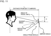
- Fig. 11 is a diagram illustrating a third example of the processing that is executed by the information decision unit 120 in step S360 in Fig. 8 .
- the information decision unit 120 generates information indicating a vertical angle of the side mirror 36, as at least a part of the setting information.
- an angle Y 2 when a visual line of a user seated on the seat 32 is reflected by the side mirror 36 is also required to be a value desired by the user.
- the information decision unit 120 generates the first setting information relating to the side mirror 36 in such a way that the angle Y 2 according to the setting information of the vehicle type A and the angle Y 2 according to the setting information of the vehicle type B are the same values.
- the movable portion information includes the following information.
- the setting information includes the following information.
- the information decision unit 120 reads out physical body information of a driver (user) from the first storage unit 140.
- the physical body information includes a seated height.
- the information decision unit 120 computes the distance L 1 .
- a method for computing the distance L 1 is as described with reference to Fig. 10 .
- the information decision unit 120 computes an interval H between the side mirror 36 and an eye of a driver in the height direction.
- the interval H is computed based on ""the height of the seat surface of the seat 32 with the ground surface as a reference when the seat 32 is at the reference position" + “the change amount of the height of the seat 32 from the reference position" + "a seated height of a driver” - "(the height of the side mirror 36 with the ground surface as a reference)"".
- the information decision unit 120 computes an angle of visual line ⁇ 2 of a driver relating to the height direction.
- the angle ⁇ 2 is "arctan(H/L 1 )".
- the information decision unit 120 computes a mirror angle ⁇ 2 (with vertical direction as a reference) according to the setting information of the vehicle type A by using the second reference angle and the inclination of the side mirror 36 in the setting information. Further, the information decision unit 120 computes an incident angle of a visual line of a driver according to the setting information of the vehicle type A. The incident angle is the angle ⁇ 2 of the visual line + the mirror angle ⁇ 2 ).
- the information decision unit 120 computes the angle Y 2 in the vehicle type A.
- the information decision unit 120 can compute the angle Y 2 in the vehicle type B. Further, the information decision unit 120 sets the mirror angle ⁇ 2 in the vehicle type B in such a way that the angle Y 2 in the vehicle type B is the same value as the angle Y 2 of the vehicle type A. Further, the information decision unit 120 generates information indicating the vertical angle of the side mirror 36 in the vehicle type B by using the mirror angle ⁇ 2 and the second reference angle of the vehicle type B.
- a user of the vehicle 30 is not required to individually set a state of a setting target such as a position of a seat and an angle of a side mirror.
- a state of a setting target such as a position of a seat and an angle of a side mirror.
- operations that a user is required to do is reduced at the time of changing the setting of the setting target to a user's preferred state.
- face information is used as user determination information
- a user is not required to input the user determination information, and hence there is almost no operation for the user to do.
- the first storage unit 140 stores setting information for each vehicle type and for each user.
- the vehicle setting apparatus 10 when setting information relating to a vehicle type that is currently used by a user is not stored in the first storage unit 140, the vehicle setting apparatus 10 generates setting information relating to the vehicle type being currently used by using setting information relating to another vehicle type. It is highly likely that the setting indicated by the setting information is close to a preference of a user. Therefore, operations that a user is required to do is reduced.
- the plurality of steps are described in order, but the execution order of the steps executed in each of the example embodiments is not limited to the described order.
- the order of the illustrated steps may be changed within a range that does not interfere with the contents.
- the example embodiments described above may be combined with each other within a range that the contents do not contradict with each other.
Landscapes
- Engineering & Computer Science (AREA)
- Computer Security & Cryptography (AREA)
- Automation & Control Theory (AREA)
- Theoretical Computer Science (AREA)
- Mechanical Engineering (AREA)
- General Physics & Mathematics (AREA)
- General Engineering & Computer Science (AREA)
- Physics & Mathematics (AREA)
- Software Systems (AREA)
- Human Computer Interaction (AREA)
- Transportation (AREA)
- Computer Hardware Design (AREA)
- Fittings On The Vehicle Exterior For Carrying Loads, And Devices For Holding Or Mounting Articles (AREA)
Applications Claiming Priority (1)
| Application Number | Priority Date | Filing Date | Title |
|---|---|---|---|
| PCT/JP2021/021328 WO2022254684A1 (ja) | 2021-06-04 | 2021-06-04 | 車両設定装置、車載装置、車両設定システム、車両設定方法、及びプログラム |
Publications (2)
| Publication Number | Publication Date |
|---|---|
| EP4331919A1 true EP4331919A1 (de) | 2024-03-06 |
| EP4331919A4 EP4331919A4 (de) | 2024-07-03 |
Family
ID=84322930
Family Applications (1)
| Application Number | Title | Priority Date | Filing Date |
|---|---|---|---|
| EP21944180.5A Pending EP4331919A4 (de) | 2021-06-04 | 2021-06-04 | Fahrzeugeinstellungsvorrichtung, fahrzeugbordvorrichtung, fahrzeugeinstellungssystem, fahrzeugeinstellungsverfahren und programm |
Country Status (4)
| Country | Link |
|---|---|
| US (1) | US20240270262A1 (de) |
| EP (1) | EP4331919A4 (de) |
| JP (1) | JP7589809B2 (de) |
| WO (1) | WO2022254684A1 (de) |
Families Citing this family (5)
| Publication number | Priority date | Publication date | Assignee | Title |
|---|---|---|---|---|
| US12528442B2 (en) | 2020-03-06 | 2026-01-20 | Sonatus, Inc. | System, method, and apparatus for managing vehicle data collection |
| US12403921B2 (en) | 2020-03-06 | 2025-09-02 | Sonatus, Inc. | System, method, and apparatus for managing vehicle automation |
| US12573245B2 (en) | 2020-03-06 | 2026-03-10 | Sonatus, Inc. | System, method, and apparatus for managing vehicle automation |
| JP2025012592A (ja) * | 2023-07-13 | 2025-01-24 | トヨタ自動車株式会社 | 情報処理装置及び車両 |
| WO2025122963A1 (en) * | 2023-12-06 | 2025-06-12 | Sonatus, Inc. | Systems, methods, and apparatuses for vehicle personalization |
Family Cites Families (6)
| Publication number | Priority date | Publication date | Assignee | Title |
|---|---|---|---|---|
| JP2007245831A (ja) * | 2006-03-14 | 2007-09-27 | Nissan Motor Co Ltd | 運転姿勢調整装置及び運転姿勢調整方法 |
| JP2014151892A (ja) | 2013-02-14 | 2014-08-25 | Hitachi Industry & Control Solutions Ltd | 車両共有化システムにおける車内環境変更装置及び車内環境変更方法 |
| JP2017033320A (ja) * | 2015-08-01 | 2017-02-09 | Ntn株式会社 | 電気自動車の調整装置 |
| JP2018154239A (ja) * | 2017-03-17 | 2018-10-04 | パナソニックIpマネジメント株式会社 | 設定装置、通信装置および設定システム |
| JP6744338B2 (ja) | 2018-01-18 | 2020-08-19 | 矢崎エナジーシステム株式会社 | 通信システム |
| JP2020133233A (ja) | 2019-02-19 | 2020-08-31 | 株式会社デンソー | 車両用情報管理装置 |
-
2021
- 2021-06-04 US US18/565,232 patent/US20240270262A1/en active Pending
- 2021-06-04 JP JP2023525305A patent/JP7589809B2/ja active Active
- 2021-06-04 EP EP21944180.5A patent/EP4331919A4/de active Pending
- 2021-06-04 WO PCT/JP2021/021328 patent/WO2022254684A1/ja not_active Ceased
Also Published As
| Publication number | Publication date |
|---|---|
| JPWO2022254684A1 (de) | 2022-12-08 |
| EP4331919A4 (de) | 2024-07-03 |
| WO2022254684A1 (ja) | 2022-12-08 |
| US20240270262A1 (en) | 2024-08-15 |
| JP7589809B2 (ja) | 2024-11-26 |
Similar Documents
| Publication | Publication Date | Title |
|---|---|---|
| EP4331919A1 (de) | Fahrzeugeinstellungsvorrichtung, fahrzeugbordvorrichtung, fahrzeugeinstellungssystem, fahrzeugeinstellungsverfahren und programm | |
| CN108137052B (zh) | 驾驶控制装置、驾驶控制方法和计算机可读介质 | |
| US20170343375A1 (en) | Systems to dynamically guide a user to an autonomous-driving vehicle pick-up location by augmented-reality walking directions | |
| JP6509361B2 (ja) | 駐車支援装置及び駐車支援方法 | |
| US20200242529A1 (en) | Vehicle dispatch system, vehicle dispatch method, server, user terminal, and storage medium | |
| US11256936B2 (en) | Vehicle occupant count monitoring system | |
| CN108137050A (zh) | 驾驶控制装置、驾驶控制方法和程序 | |
| CN107924632A (zh) | 信息处理设备、信息处理方法和程序 | |
| US12092471B2 (en) | Server device, information processing system, control device, shared vehicle, and operation method for information processing system | |
| JP4096830B2 (ja) | 車載機器調整システム | |
| US20190080069A1 (en) | Operation permission authentication device | |
| EP3650267B1 (de) | Steuerungsvorrichtung für fahrzeug, system, verfahren und speichermedium | |
| CN109484344A (zh) | 用于全局化便携式乘员车辆设置的方法和设备 | |
| JPWO2022254684A5 (ja) | 車両設定装置、車載装置、車両設定システム、及び車両設定方法 | |
| CN106940783A (zh) | 车辆指纹书签 | |
| JP2010147567A (ja) | 情報提供装置及び情報提供システム | |
| JP6925130B2 (ja) | 車両制御装置及び車両制御方法 | |
| JP2025020305A (ja) | 音響装置 | |
| JP2012043364A (ja) | 物体認識装置 | |
| CN118991651A (zh) | 用于根据一个或多个钥匙装置运行车辆的方法和设备 | |
| CN116923205A (zh) | 车辆座椅调节方法、装置、车辆和存储介质 | |
| EP4535125A1 (de) | Personalisierte interaktive virtuelle umgebung in fahrzeugen | |
| JP2021088282A (ja) | 車両用通知システム及び車載装置 | |
| CN114074669A (zh) | 信息处理装置、信息处理方法以及程序 | |
| EP4596289A1 (de) | Verfahren und vorrichtung zur steuerung einer anzeige eines fahrzeugs |
Legal Events
| Date | Code | Title | Description |
|---|---|---|---|
| STAA | Information on the status of an ep patent application or granted ep patent |
Free format text: STATUS: THE INTERNATIONAL PUBLICATION HAS BEEN MADE |
|
| PUAI | Public reference made under article 153(3) epc to a published international application that has entered the european phase |
Free format text: ORIGINAL CODE: 0009012 |
|
| STAA | Information on the status of an ep patent application or granted ep patent |
Free format text: STATUS: REQUEST FOR EXAMINATION WAS MADE |
|
| 17P | Request for examination filed |
Effective date: 20231201 |
|
| AK | Designated contracting states |
Kind code of ref document: A1 Designated state(s): AL AT BE BG CH CY CZ DE DK EE ES FI FR GB GR HR HU IE IS IT LI LT LU LV MC MK MT NL NO PL PT RO RS SE SI SK SM TR |
|
| A4 | Supplementary search report drawn up and despatched |
Effective date: 20240603 |
|
| RIC1 | Information provided on ipc code assigned before grant |
Ipc: B60R 16/037 20060101AFI20240527BHEP |
|
| DAV | Request for validation of the european patent (deleted) | ||
| DAX | Request for extension of the european patent (deleted) |