EP4331943A1 - Réseau de transport et procédé de fonctionnement de véhicules ferroviaires dans un réseau de transport comprenant une combinaison de sections de voie avec et sans protection contre les trains - Google Patents
Réseau de transport et procédé de fonctionnement de véhicules ferroviaires dans un réseau de transport comprenant une combinaison de sections de voie avec et sans protection contre les trains Download PDFInfo
- Publication number
- EP4331943A1 EP4331943A1 EP22192956.5A EP22192956A EP4331943A1 EP 4331943 A1 EP4331943 A1 EP 4331943A1 EP 22192956 A EP22192956 A EP 22192956A EP 4331943 A1 EP4331943 A1 EP 4331943A1
- Authority
- EP
- European Patent Office
- Prior art keywords
- operating area
- automated
- train
- rail vehicles
- monitoring
- Prior art date
- Legal status (The legal status is an assumption and is not a legal conclusion. Google has not performed a legal analysis and makes no representation as to the accuracy of the status listed.)
- Pending
Links
Images

Classifications
-
- B—PERFORMING OPERATIONS; TRANSPORTING
- B61—RAILWAYS
- B61L—GUIDING RAILWAY TRAFFIC; ENSURING THE SAFETY OF RAILWAY TRAFFIC
- B61L27/00—Central railway traffic control systems; Trackside control; Communication systems specially adapted therefor
- B61L27/02—Manual systems
-
- B—PERFORMING OPERATIONS; TRANSPORTING
- B61—RAILWAYS
- B61L—GUIDING RAILWAY TRAFFIC; ENSURING THE SAFETY OF RAILWAY TRAFFIC
- B61L27/00—Central railway traffic control systems; Trackside control; Communication systems specially adapted therefor
- B61L27/04—Automatic systems, e.g. controlled by train; Change-over to manual control
-
- B—PERFORMING OPERATIONS; TRANSPORTING
- B61—RAILWAYS
- B61L—GUIDING RAILWAY TRAFFIC; ENSURING THE SAFETY OF RAILWAY TRAFFIC
- B61L25/00—Recording or indicating positions or identities of vehicles or trains or setting of track apparatus
- B61L25/02—Indicating or recording positions or identities of vehicles or trains
- B61L25/025—Absolute localisation, e.g. providing geodetic coordinates
-
- B—PERFORMING OPERATIONS; TRANSPORTING
- B61—RAILWAYS
- B61L—GUIDING RAILWAY TRAFFIC; ENSURING THE SAFETY OF RAILWAY TRAFFIC
- B61L27/00—Central railway traffic control systems; Trackside control; Communication systems specially adapted therefor
- B61L27/10—Operations, e.g. scheduling or time tables
-
- B—PERFORMING OPERATIONS; TRANSPORTING
- B61—RAILWAYS
- B61L—GUIDING RAILWAY TRAFFIC; ENSURING THE SAFETY OF RAILWAY TRAFFIC
- B61L27/00—Central railway traffic control systems; Trackside control; Communication systems specially adapted therefor
- B61L27/20—Trackside control of safe travel of vehicle or train, e.g. braking curve calculation
-
- B—PERFORMING OPERATIONS; TRANSPORTING
- B60—VEHICLES IN GENERAL
- B60Y—INDEXING SCHEME RELATING TO ASPECTS CROSS-CUTTING VEHICLE TECHNOLOGY
- B60Y2200/00—Type of vehicle
- B60Y2200/30—Railway vehicles
-
- B—PERFORMING OPERATIONS; TRANSPORTING
- B61—RAILWAYS
- B61L—GUIDING RAILWAY TRAFFIC; ENSURING THE SAFETY OF RAILWAY TRAFFIC
- B61L27/00—Central railway traffic control systems; Trackside control; Communication systems specially adapted therefor
- B61L27/20—Trackside control of safe travel of vehicle or train, e.g. braking curve calculation
- B61L2027/204—Trackside control of safe travel of vehicle or train, e.g. braking curve calculation using Communication-based Train Control [CBTC]
-
- B—PERFORMING OPERATIONS; TRANSPORTING
- B61—RAILWAYS
- B61L—GUIDING RAILWAY TRAFFIC; ENSURING THE SAFETY OF RAILWAY TRAFFIC
- B61L27/00—Central railway traffic control systems; Trackside control; Communication systems specially adapted therefor
- B61L27/10—Operations, e.g. scheduling or time tables
- B61L27/14—Following schedules
-
- B—PERFORMING OPERATIONS; TRANSPORTING
- B61—RAILWAYS
- B61L—GUIDING RAILWAY TRAFFIC; ENSURING THE SAFETY OF RAILWAY TRAFFIC
- B61L27/00—Central railway traffic control systems; Trackside control; Communication systems specially adapted therefor
- B61L27/70—Details of trackside communication
Definitions
- the invention relates to a method for operating rail vehicles in a transport network.
- the invention also relates to a transport network for operating rail vehicles.
- the invention further relates to a rail vehicle for operation in a transport network.
- the invention relates to a computer program and a provision device for this computer program, the computer program being equipped with program instructions for carrying out this method.
- CBTC Communication-Based Train Control
- train control operations in an operating area reserved for rail vehicles
- a computer-aided process based on bidirectional communication for central train monitoring and operational management with the partial functions of automated train protection, automated operation and automated monitoring is carried out there.
- point-like unidirectional communication e.g. with IMU coupling coils, IMU stands for inductive message transmission
- IMU stands for inductive message transmission
- the areas are treated separately during implementation. It is therefore not possible for the operator to accurately track train movements in operating areas with visual driving that are shared with other road users.
- On the control technology page only operating areas reserved exclusively for rail vehicles are shown. In the cockpit of the train there is an HMI for the reserved operating area with automated train protection (train protection operation).
- Metro and long-distance rail systems often use continuous Monitoring is used to prevent driving over danger points, such as ETCS (European Train Control System), PTC (Positive Train Control) and CBTC (Communication-Based Train Control).
- Continuous monitoring enables automated train control using continuous train running operation and eliminates the need to set up a large number of trackside devices, although the system of continuous monitoring is significantly more complex elsewhere. For trams that travel partially underground or pass through longer tunnels, continuous monitoring is only carried out there, for example CBTC.
- CBTC Common-Based Train Control
- trackside devices such as coupling coils, which are installed in the road on the track and corresponding components for communication in the vehicle, are used, which only ensure message transmission but have no safety-relevant function.
- the components of visual driving operation mentioned require a certain amount of installation space.
- low-floor vehicles e.g. trams
- space problems arise when installing the components mentioned, particularly in the underfloor area.
- the components require a certain amount of maintenance to avoid malfunctions.
- components installed in the track of trams are not only run over by the tram, but also by other vehicles that use the road. This causes increased mechanical stress on the components, which also increases their susceptibility to failure.
- the object of the invention is to provide a method and a transport network (containing routes consisting of railway tracks) for operating rail vehicles, which is divided into components installed in particular on or in the track with the lowest possible technical and/or financial outlay Operating area ensures the greatest possible range of functions both in an operating area reserved only for train traffic and in a traffic area shared with other road users.
- the object of the invention is to provide a computer program and a provision device for this computer program with which the aforementioned method can be carried out.
- bidirectional communication means that both data is transmitted from the rail vehicle towards the track side and data is transmitted from the track side towards the rail vehicle.
- Suitable communication devices are used in the rail vehicle and transport network. These can be designed according to the CBTC standard (primarily in the reserved operating area) or, according to the invention, also use the V2X standard (primarily in the shared operating area).
- Continuous train tracking can preferably be achieved, while in the divided operating area for train protection, visual driving can be carried out by a train driver, ie the train driver carries the entire train Safety responsibility.
- Continuous train tracking also makes it possible to locate the train if, in the event of a gradual system change (migration from old technology to new technology), track-side facilities in the transport network such as induction loops or balises are used in parallel for tracking purposes. This is done for the purpose of, for example, adapting the timetable if delays occur. For this purpose, it is necessary to locate the rail vehicles traveling in the transport network at a local or temporal density so that the adaptation of the timetable or another task based on the location can be carried out.
- continuous refers to a density of locating events (event of successful locating of the rail vehicle) that makes the task in question reliably executable. From a technical point of view, this can also be achieved, for example, through quasi-continuous positioning, in which there is a finite number of positioning events on a specific section of the route. A quasi-continuous location should therefore be included in the term “continuous”.
- the method according to the invention brings a variety of advantages.
- the solution saves both the track equipment in the track and the corresponding vehicle antennas in visual driving operation, which would have to be used with a classic point-shaped message transmission device (e.g. IMU). This leads to significant savings and solves problems with installing the required vehicle coupling coils in the underfloor area, especially in low-floor trams. Instead, the vehicle has a localization and data transmission system as well as the necessary combination antennas (e.g. GPS, mobile communications, WLAN) installed to transmit data relating to the implemented applications. Because a vehicle data communication system such as V2X is used for this purpose, the solution can be implemented comparatively cost-effectively. Since there is no train protection operation, COTS components can be used, for example (COTS are components of the shelf, i.e.
- COTS components can also be used in the transport network, which may already be present due to the use of a V2X partial infrastructure in particular, as these have already been installed for other road users in the shared operating area (e.g. participants in motorized private transport). This means that installation costs can be saved at least to the extent that the already installed components can be used.
- a preferably reduced range of components adapted to the modified functional scope of visual driving operation can be installed on the route, or an infrastructure that has already been installed in the shared operating area, such as V2X, can be used.
- the invention differs from existing systems in that no or at least fewer trackside devices are necessary in the track.
- the system thus offers easy-to-implement, digital, space-saving functions, especially for tram systems, without the need for complex installation of devices under the vehicle floor and in the track bed.
- the digital or virtual functions can therefore preferably also be used in low-floor vehicles with limited space (for example trams).
- “computer-aided” or “computer-implemented” can be understood to mean an implementation of the method in which at least one computer or processor carries out at least one method step of the method.
- Computers can be, for example, personal computers, servers, handheld computers, mobile radio devices and other communication devices that process data using computers, processors and other electronic devices for data processing, which can preferably also be connected to form a network via interfaces.
- a “processor” can be understood to mean, for example, a converter, a sensor for generating measurement signals or an electronic circuit.
- a processor can in particular be a main processor (Central Processing Unit, CPU), a microprocessor, a microcontroller, or a digital signal processor, possibly in combination with a memory unit for storing program instructions and data.
- CPU Central Processing Unit
- a processor can also be understood as a virtualized processor or a soft CPU.
- a “memory unit” can be understood to mean, for example, a computer-readable memory in the form of a random access memory (RAM) or data memory (hard drive or data carrier).
- RAM random access memory
- data memory hard drive or data carrier
- Interfaces can be implemented in terms of hardware, for example wired or as a radio connection, and/or software, for example as an interaction between individual program modules or program parts of one or more computer programs.
- Program modules are intended to be understood as individual functional units that enable a program sequence of method steps according to the invention. These functional units can be implemented in a single computer program or in several computer programs communicating with each other. The interfaces implemented here can be implemented in software terms within a single processor or in hardware terms if several processors are used.
- a modified range of functions should preferably be understood as a range of functions that only contains functions that are classified as not safety-relevant for the operation of the rail vehicle (no automated train protection, but automated operation and monitoring).
- IEC 61508 or specifically for the railway sector according to the European standard EN 50129
- four safety integrity levels (SIL-1 to SIL-4) or safety requirement levels are distinguished for safety functions.
- security integrity level 4 represents the highest level of security integrity
- security integrity level 1 represents the lowest level of security integrity.
- the respective security integrity level influences the trust interval of a measured value in such a way that the higher the security integrity level, the smaller the trust interval is which must be fulfilled by the respective device.
- the modified range of functions only includes functions that are not safety-relevant, this has the advantage that the hardware infrastructure on the route itself that accompanies visual driving does not Must meet requirements for increased security.
- the knowledge is used that in visual driving operation the train driver is responsible for safety-relevant functions, so that the automatically implemented functions themselves do not endanger the safety of the operation of the rail vehicle.
- the continuous location of the rail vehicle in a shared operating area can be mentioned.
- This is not used for safety-relevant functions of rail operations.
- the vehicle driver will make driving decisions for the vehicle in visual driving mode based on his own judgments, regardless of the position determined.
- the location can be used for non-safety-relevant applications (so-called comfort functions), such as an adaptive timetable. If, with such a function, the position determined by location does not correspond to the actual position, this does not affect the safety of the rail vehicle as such but would only lead to a possibly insufficiently optimized timetable. However, the resulting delays would not pose a safety risk for rail vehicle users.
- the automated operation and monitoring uniformly implements at least one of the following functions: determination and transmission of arrival information of the rail vehicles, operational management with a possibility of optimizing the timetable, continuous train tracking.
- Comfort functions are characterized by the fact that they are not necessary for the operation of the rail vehicle from a safety perspective. However, the fulfillment of comfort functions can improve the usability of the operation of the rail vehicles in the transport network in question. Improvements can be in the performance of the operation, for example a closer timing of consecutive trains in the transport network. Or in improving use by passengers, for example by predicting the actual arrival times of a rail vehicle at the station. Overall, the comfort functions offered lead to greater acceptance among passengers and, advantageously, to wider use.
- the transport network according to the invention with which the method according to the invention can be carried out, can be set up without an investment or at least with reduced investments in the hardware infrastructure on the route.
- the train protection system thus accesses an infrastructure corresponding to the safety requirements in train protection operation and, in visual driving operation, accesses another infrastructure, preferably already existing, to implement the desired function that is not safety-relevant.
- the comfort functions can then be made available seamlessly both in train control operation and in visual driving operation, which advantageously greatly simplifies the implementation of these comfort functions (regardless of whether this is automated or, for example, in a control center) and provides additional potential for the realization of the comfort functions throughout the transport network.
- the method for automated train control is based on CBTC.
- CBTC Communication-Based Train Control
- a system works in both directions
- Data communication takes place between the vehicle and track equipment, and precise track clearance notification is used independently of track equipment such as track circuits, which enables driving in a moving spatial distance (the moving block).
- the basic function of the system can be expanded to include door control or passenger information.
- the requirements and general system architecture of CBTC systems are defined in IEEE Standard 1474.1.
- a provision device for storing and/or providing the computer program.
- the provision device is, for example, a storage unit that stores and/or provides the computer program.
- the provision device is, for example, a network service, a computer system, a server system, in particular a distributed, for example cloud-based, computer system and/or virtual computer system, which stores and/or provides the computer program, preferably in the form of a data stream.
- the provision takes place in the form of a program data block as a file, in particular as a download file, or as a data stream, in particular as a download data stream, of the computer program.
- This provision can also be made, for example, as a partial download consisting of several parts.
- Such a computer program is read into a system using the provision device, for example, so that the method according to the invention is carried out on a computer.
- a traffic network is shown schematically, which is provided, for example, by a track GL of the route forming the traffic network for a vehicle FZ that moves in a direction of travel FR.
- the route has a reserved RBB operating area, where only FZ rail vehicles are allowed to operate. This is the case in a tunnel TL.
- Other road users can enter this divided operating area GBB Figure 1 are not shown in more detail, cross the GL track or drive in its area (pedestrians, cyclists, motor vehicles).
- the GL track can accommodate trackside facilities such as: B. have a balise BL and another route element IMU, which is formed by an inductive electrical loop.
- the track element IMU is embedded in the subsoil supporting the GL track and is not shown in more detail.
- control elements W1, W2 are shown in the form of switches. These determine the route of the FZ rail vehicle in the transport network.
- the control elements W1, W2 are controlled by controllers CL1, CL2, which implement corresponding control commands.
- an actuating command is passed on via the route element IMU via a third interface S3 to the first controller CL1, which implements the actuating command via a thirteenth interface S13 in order to set the first actuating element W1.
- an actuating command is sent, for example, via a tenth interface S10 initiated, the tenth interface S10 being a radio interface between two antennas AT, each in the rail vehicle FZ and in a processing unit (for example a converter) CV. This can be e.g. B. be a V2X interface.
- the processing unit CV converts the signal received via the tenth interface S10 and sends it to the second controller CL2 via a fourth interface S4.
- the signal converted by the processing unit CV is available in the same format as the signal generated by the route element IMU and transmitted to the first controller CL1 via the third interface S3. Therefore, the second controller CL2 can give an actuating command to the second actuating element W2 via a twelfth interface S12.
- the route element IMU transmits a signal via the third interface S3 depending on whether the rail vehicle FZ has passed.
- the track element IMU is designed as a sensor for detecting the passage of rail vehicles FZ.
- this route element can be replaced by the processing unit CV, which enables a signal to be sent directly from the rail vehicle FZ via its antenna AT (tenth interface S10).
- This uses an IT infrastructure based on the V3X standard, which is at least partially already present in the transport network and which can be retrofitted cost-effectively with COTS components in the rail vehicle.
- a network is formed by a large number of antennas AT, which enables communication.
- a control center LZ is also involved in this, in which, for example, adaptive train plans can be created and which is involved in the processing of a CBTC procedure in the reserved RBB operating area.
- the control center LZ communicates via a first interface S1 with a signal box STW, which in turn communicates via a second interface S2 with a CBTC unit CBTC-U to carry out a CBTC method in the tunnel TL. It is a balise in the tunnel but about a so-called fixed data balise which is involved in the implementation of the CBTC procedure.
- the rail vehicle FZ communicates with the control center LZ via a sixth interface S6. Additional interfaces may be provided, even if this is not specified Figure 1 is shown.
- the rail vehicle FZ communicates with antennas AT in the tunnel TL via interfaces (not shown) so that a connection can be established via the interface S5 to the CBTC unit CBTC-U.
- the train control operation in the TL tunnel via CBTC, and the visual driving operation, in which a driver (not shown) drives the rail vehicle FZ is a service with a modified range of functions compared to the automated train control operation, with automated operation and monitoring of the rail vehicle is carried out.
- This service preferably uses the V2X standard for communication.
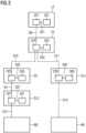
- FIG 2 can be seen as a network as shown in Figure 1 can be designed for the shared operating area (GBB).
- the control center LZ has a first computer CP1 with a first storage unit SE1, which is connected to the first computer CP1 via a twenty-first interface S21.
- the computer CP1 of the control center LZ communicates with a computer CP2 in the rail vehicle FZ via the sixth interface S6. Details on the transmission technology are in Figure 2 not shown.
- the rail vehicle FZ has the second computer CP2, which is connected to a second memory unit SE2 via a twenty-second interface S22.
- the second computer CP2 communicates via the tenth interface S10 with a fifth computer CP5 in the processing unit CV, which also has a fifth storage unit SE5 which is connected to the fifth computer CP5 via a twenty-fifth interface S25.
- the fifth computer CP5 communicates via the fourth interface S4 with a seventh computer CP7 of the second controller CL2, the seventh computer CP7 being connected to a seventh memory unit SE7 via a twenty-seventh interface S27.
- the second controller CL2 can Control the second control element W2 with the seventh computer CP7 via the twelfth interface S12.
- the rail vehicle FZ also communicates with a sixth computer CP6 of the first controller CL1 via the eleventh interface S11. This consists of a crossing over the route element IMU, whereby a signal is triggered inductively.
- the first controller CL1 also has a sixth memory unit SE6, which is connected to the sixth computer CP6 via a twenty-sixth interface S26.
- the sixth computer CP6 can in turn control the first control element W1 via the thirteenth interface S13.
Landscapes
- Engineering & Computer Science (AREA)
- Mechanical Engineering (AREA)
- Train Traffic Observation, Control, And Security (AREA)
- Electric Propulsion And Braking For Vehicles (AREA)
Priority Applications (3)
| Application Number | Priority Date | Filing Date | Title |
|---|---|---|---|
| EP22192956.5A EP4331943A1 (fr) | 2022-08-30 | 2022-08-30 | Réseau de transport et procédé de fonctionnement de véhicules ferroviaires dans un réseau de transport comprenant une combinaison de sections de voie avec et sans protection contre les trains |
| CN202311104486.9A CN117622267A (zh) | 2022-08-30 | 2023-08-29 | 由有和无列车安全的路段组成的交通网络和轨道车辆运行方法 |
| US18/458,333 US20240067243A1 (en) | 2022-08-30 | 2023-08-30 | Traffic network and method for operating rail vehicles in a traffic network consisting of a combination of line sections with train protection and line sections without train protection |
Applications Claiming Priority (1)
| Application Number | Priority Date | Filing Date | Title |
|---|---|---|---|
| EP22192956.5A EP4331943A1 (fr) | 2022-08-30 | 2022-08-30 | Réseau de transport et procédé de fonctionnement de véhicules ferroviaires dans un réseau de transport comprenant une combinaison de sections de voie avec et sans protection contre les trains |
Publications (1)
| Publication Number | Publication Date |
|---|---|
| EP4331943A1 true EP4331943A1 (fr) | 2024-03-06 |
Family
ID=83151706
Family Applications (1)
| Application Number | Title | Priority Date | Filing Date |
|---|---|---|---|
| EP22192956.5A Pending EP4331943A1 (fr) | 2022-08-30 | 2022-08-30 | Réseau de transport et procédé de fonctionnement de véhicules ferroviaires dans un réseau de transport comprenant une combinaison de sections de voie avec et sans protection contre les trains |
Country Status (3)
| Country | Link |
|---|---|
| US (1) | US20240067243A1 (fr) |
| EP (1) | EP4331943A1 (fr) |
| CN (1) | CN117622267A (fr) |
Cited By (1)
| Publication number | Priority date | Publication date | Assignee | Title |
|---|---|---|---|---|
| EP4696584A1 (fr) * | 2024-08-12 | 2026-02-18 | Siemens Mobility AG | Procédé de transmission et de vérification de données de direction de train |
Families Citing this family (1)
| Publication number | Priority date | Publication date | Assignee | Title |
|---|---|---|---|---|
| CN119527397A (zh) * | 2025-01-23 | 2025-02-28 | 北京城建智控科技股份有限公司 | 列车控制方法及装置 |
Citations (1)
| Publication number | Priority date | Publication date | Assignee | Title |
|---|---|---|---|---|
| KR101262036B1 (ko) * | 2012-10-09 | 2013-05-08 | 주식회사 에스에이치에이치(Shh) | 도시교통정보시스템과 연계된 트램 제어 시스템 |
Family Cites Families (1)
| Publication number | Priority date | Publication date | Assignee | Title |
|---|---|---|---|---|
| CN110588726A (zh) * | 2019-09-26 | 2019-12-20 | 公安部交通管理科学研究所 | 一种基于lte-v2x的有轨电车信号优先控制系统与方法 |
-
2022
- 2022-08-30 EP EP22192956.5A patent/EP4331943A1/fr active Pending
-
2023
- 2023-08-29 CN CN202311104486.9A patent/CN117622267A/zh active Pending
- 2023-08-30 US US18/458,333 patent/US20240067243A1/en active Pending
Patent Citations (1)
| Publication number | Priority date | Publication date | Assignee | Title |
|---|---|---|---|---|
| KR101262036B1 (ko) * | 2012-10-09 | 2013-05-08 | 주식회사 에스에이치에이치(Shh) | 도시교통정보시스템과 연계된 트램 제어 시스템 |
Non-Patent Citations (2)
| Title |
|---|
| CLEIREC ET AL: "Le SAEIV", REVUE GÉNÉRALE DES CHEMINS DE FER : RCGF, HC ÉDITIONS, FR, no. 243, 1 November 2014 (2014-11-01), pages 6 - 20, XP001526566, ISSN: 0035-3183 * |
| MCCULLOUGH I: "Trends in modern mass-transit train control", SIGNAL UND DRAHT: SIGNALLING & DATACOMMUNICATION, EURAILPRESS, DE, vol. 100, no. 10, 1 October 2008 (2008-10-01), pages 41 - 47, XP001515418, ISSN: 0037-4997 * |
Cited By (1)
| Publication number | Priority date | Publication date | Assignee | Title |
|---|---|---|---|---|
| EP4696584A1 (fr) * | 2024-08-12 | 2026-02-18 | Siemens Mobility AG | Procédé de transmission et de vérification de données de direction de train |
Also Published As
| Publication number | Publication date |
|---|---|
| CN117622267A (zh) | 2024-03-01 |
| US20240067243A1 (en) | 2024-02-29 |
Similar Documents
| Publication | Publication Date | Title |
|---|---|---|
| EP2691255B1 (fr) | Procédé de fonctionnement de véhicules sur rails | |
| DE102014210190A1 (de) | Fahrerlaubnis für ein Schienenfahrzeug | |
| DE102015210427A1 (de) | Verfahren sowie Einrichtung zum Ermitteln einer Fahrerlaubnis für ein spurgebundenes Fahrzeug | |
| EP3782869B1 (fr) | Procédé de commande d'un train dans un système de protection des trains, système de protection des trains | |
| EP3247609A1 (fr) | Procédé et dispositif servant à influencer de manière automatique des véhicules guidés sur rails | |
| EP2870047B1 (fr) | Fonctionnement d'un véhicule ferroviaire | |
| EP3124351A1 (fr) | Procédé de post-équipement de parties de réseau ferroviaire existant avec un système de sécurisation de train | |
| WO2014044541A2 (fr) | Commande de véhicules ferroviaires | |
| EP3795451B1 (fr) | Procédé de localisation d'un véhicule dans une station destinée à un arrêt du véhicule | |
| EP2663483B1 (fr) | Dispositif de contrôle des trains pour système etcs l2 - système européen de contrôle des trains, niveau 2 - | |
| EP2619067B1 (fr) | Procédé pour commander automatiquement une pluralité de véhicules guidés | |
| DE102019211966A1 (de) | Gleisgebundener Streckenabschnitt, ausgestattet mit einem automatischen Zugsicherungssystem, und Verfahren zu dessen Betrieb | |
| EP3925851A1 (fr) | Système et procédé pour effectuer un controle d'entrée pour un véhicule ferroviaire | |
| EP4124540A1 (fr) | Procédé et dispositif permettant de faire fonctionner un arrêt automatique pour un véhicule guidé sur rails | |
| EP4408720A1 (fr) | Procédé d'activation d'une pluralité de portes dans un véhicule | |
| EP3768568B1 (fr) | Véhicule ferroviaire comprenant un dispositif de commande | |
| EP3768567B1 (fr) | Procédé pour préparer ou commander les déplacements d'une pluralité de véhicules dans un réseau de voies de circulation | |
| EP3400161A1 (fr) | Installation technique ferroviaire et procédé de fonctionnement d'une installation technique ferroviaire | |
| EP4331939A1 (fr) | Réseau de trafic et procédé de fonctionnement de véhicules ferroviaires dans un réseau de trafic | |
| DE19501993C2 (de) | Verfahren und Einrichtung zur sicherheitsrelevanten Erfassung und Verarbeitung von Zustandsinformationen dezentraler oder zentraler Steuereinrichtungen von Fahrwegelementen entlang eines Fahrwegs auf Triebfahrzeugen | |
| EP3943363B1 (fr) | Système de commande ferroviaire à blocage de commande | |
| DE102014002297A1 (de) | Verfahren zum vorbildgerechten Betreiben von Modellfahrzeugen einer Modellbahnanlage | |
| DE102011081995A1 (de) | Fahrtoptimierungsmodul | |
| DE102015217596A1 (de) | Kommunikationseinrichtung und Verfahren zum automatisierten Austausch von Nachrichten in einer eisenbahntechnischen Anlage | |
| EP3960580A1 (fr) | Système de commande ferroviaire doté d'un adaptateur d'interface et procédé de configuration |
Legal Events
| Date | Code | Title | Description |
|---|---|---|---|
| PUAI | Public reference made under article 153(3) epc to a published international application that has entered the european phase |
Free format text: ORIGINAL CODE: 0009012 |
|
| STAA | Information on the status of an ep patent application or granted ep patent |
Free format text: STATUS: THE APPLICATION HAS BEEN PUBLISHED |
|
| AK | Designated contracting states |
Kind code of ref document: A1 Designated state(s): AL AT BE BG CH CY CZ DE DK EE ES FI FR GB GR HR HU IE IS IT LI LT LU LV MC MK MT NL NO PL PT RO RS SE SI SK SM TR |
|
| STAA | Information on the status of an ep patent application or granted ep patent |
Free format text: STATUS: REQUEST FOR EXAMINATION WAS MADE |
|
| 17P | Request for examination filed |
Effective date: 20240318 |
|
| RBV | Designated contracting states (corrected) |
Designated state(s): AL AT BE BG CH CY CZ DE DK EE ES FI FR GB GR HR HU IE IS IT LI LT LU LV MC MK MT NL NO PL PT RO RS SE SI SK SM TR |
|
| RAP3 | Party data changed (applicant data changed or rights of an application transferred) |
Owner name: SIEMENS MOBILITY GMBH |