EP4331983B1 - Procédés et appareil pour aligner et sécuriser un aéronef - Google Patents
Procédés et appareil pour aligner et sécuriser un aéronef Download PDFInfo
- Publication number
- EP4331983B1 EP4331983B1 EP24153278.7A EP24153278A EP4331983B1 EP 4331983 B1 EP4331983 B1 EP 4331983B1 EP 24153278 A EP24153278 A EP 24153278A EP 4331983 B1 EP4331983 B1 EP 4331983B1
- Authority
- EP
- European Patent Office
- Prior art keywords
- aircraft
- wing
- paddles
- wings
- guide
- Prior art date
- Legal status (The legal status is an assumption and is not a legal conclusion. Google has not performed a legal analysis and makes no representation as to the accuracy of the status listed.)
- Active
Links
Images


Classifications
-
- B—PERFORMING OPERATIONS; TRANSPORTING
- B64—AIRCRAFT; AVIATION; COSMONAUTICS
- B64D—EQUIPMENT FOR FITTING IN OR TO AIRCRAFT; FLIGHT SUITS; PARACHUTES; ARRANGEMENT OR MOUNTING OF POWER PLANTS OR PROPULSION TRANSMISSIONS IN AIRCRAFT
- B64D5/00—Aircraft transported by aircraft, e.g. for release or reberthing during flight
-
- B—PERFORMING OPERATIONS; TRANSPORTING
- B64—AIRCRAFT; AVIATION; COSMONAUTICS
- B64C—AEROPLANES; HELICOPTERS
- B64C37/00—Convertible aircraft
- B64C37/02—Flying units formed by separate aircraft
-
- B—PERFORMING OPERATIONS; TRANSPORTING
- B64—AIRCRAFT; AVIATION; COSMONAUTICS
- B64U—UNMANNED AERIAL VEHICLES [UAV]; EQUIPMENT THEREFOR
- B64U10/00—Type of UAV
- B64U10/25—Fixed-wing aircraft
-
- B—PERFORMING OPERATIONS; TRANSPORTING
- B64—AIRCRAFT; AVIATION; COSMONAUTICS
- B64D—EQUIPMENT FOR FITTING IN OR TO AIRCRAFT; FLIGHT SUITS; PARACHUTES; ARRANGEMENT OR MOUNTING OF POWER PLANTS OR PROPULSION TRANSMISSIONS IN AIRCRAFT
- B64D39/00—Refuelling during flight
-
- B—PERFORMING OPERATIONS; TRANSPORTING
- B64—AIRCRAFT; AVIATION; COSMONAUTICS
- B64U—UNMANNED AERIAL VEHICLES [UAV]; EQUIPMENT THEREFOR
- B64U2201/00—UAVs characterised by their flight controls
- B64U2201/10—UAVs characterised by their flight controls autonomous, i.e. by navigating independently from ground or air stations, e.g. by using inertial navigation systems [INS]
- B64U2201/102—UAVs characterised by their flight controls autonomous, i.e. by navigating independently from ground or air stations, e.g. by using inertial navigation systems [INS] adapted for flying in formations
-
- B—PERFORMING OPERATIONS; TRANSPORTING
- B64—AIRCRAFT; AVIATION; COSMONAUTICS
- B64U—UNMANNED AERIAL VEHICLES [UAV]; EQUIPMENT THEREFOR
- B64U60/00—Undercarriages
- B64U60/40—Undercarriages foldable or retractable
Definitions
- This disclosure relates generally to aircraft and, more particularly, to methods and apparatus to align and secure aircraft.
- US3226056A describes the grouping of individual aircraft into a multiple unit or flight group, wherein individual components of the multiple until may be assembled or linked, as well as detached, from other components of the group, in flight.
- US3249322A describes a means of forming a serially arranged train of discrete aerodynamically supported aircraft structures, each of which carries a substantial useful load, and means for trimming, stabilizing, and controlling the overall train in flight and for trimming, stabilizing and controlling the discrete aircraft structures in the train relative to each other.
- US2863618A relates to airplanes and more particularly has to do with means for releasably interconnecting a plurality of airplanes for flight as a unified assembly.
- An example aircraft includes a first wing having a first guide, a second wing having a second guide, where the first and second guides are configured to guide the aircraft to be aligned with a second and a third aircraft during flight or hovering of the aircraft, a first lock coupled to the first wing, where the first lock is configured to secure the first wing to a third wing of the second aircraft, and a second lock coupled to the second wing, where the second lock is configured to secure the second wing to a fourth wing of the third aircraft, wherein the first and second locks each include a rotatable paddle to be received by the third and fourth wings, respectively, and wherein each of the rotatable paddles is configured to define a landing support of the aircraft.
- An example method for securing a first aircraft to a second aircraft includes contacting a first guide of a first wing of the first aircraft to a second guide of a second wing of the second aircraft, where engagement of the first guide to the second guide aligns the first wing with the second wing.
- the example method also includes securing, via a lock, the first wing to the second wing after the engagement of the first and second guides aligns the first wing to the second wing, wherein securing the first wing to the second wing includes extending a paddle into the second wing and rotating the paddle so that the paddle contacts an internal surface of a cavity of the second wing, wherein each of the rotatable paddles defines a landing support of the aircraft.
- Methods and apparatus to align and secure aircraft are disclosed. Multiple aircraft can be secured together to yield aerodynamic benefits. In particular, securing the aircraft together at their respective wings can increase aerodynamic efficiency in comparison to the individual aircraft flying separately by increasing an overall aspect ratio of the wings. In other words, a relatively larger continuous aerodynamic surface may be defined.
- the examples disclosed herein can provide quick and accurate alignment of multiple aircraft (e.g., during flight and/or hovering).
- the examples disclosed herein utilize a guide or alignment device to align wings of different aircraft to one another during flight so that a lock or restraint mechanism can be used to secure the wings together.
- the examples disclosed herein can be effectively implemented with unmanned vehicles (e.g., unmanned aerial vehicles (UAVs), unmanned fixed-wing aircraft, drones, etc.) that may be secured together to travel to a target zone or task area, detached to perform required functions separate from one another, and then secured together to return, thereby saving fuel and/or increasing potential cargo capacity in comparison to the unmanned vehicles flying separately.
- unmanned vehicles e.g., unmanned aerial vehicles (UAVs), unmanned fixed-wing aircraft, drones, etc.
- the guide and the lock includes a rotatable paddle of a first wing that is inserted into an opening of a second wing and rotated to secure the first wing to the second wing.
- the rotatable paddle may also function as a landing structure.
- the terms “guide” or “alignment device” refer to a component, feature, and/or assembly used to align a first component to a second component. Accordingly, the terms “guide” or “alignment device” can encompass a component, feature(s), a combination of engaging features, an assembly and/or a combination of multiple components, surfaces, and/or assemblies encompassing one or both of the first and second components.
- lock or “restraint mechanism” refer to a component, feature, and/or assembly used to secure the first component to the second component.
- actuated in the context of a component refers to a component that is moved by an actuator, a solenoid, or any appropriate movement device/mechanism.
- securing or “secure” refer to locking, interlocking, and/or rigidly joining two objects together.
- coupling or “couple” refer to joining two objects together, directly or indirectly joined to with another element/node/feature, and may not necessarily mean mechanically.
- the examples disclosed herein enable the first and second aircraft 102a, 102b to be aligned and secure together with relative ease by providing alignment and/or guiding features, as well as a restraint or locking system that works in tandem with the alignment and/or guiding features to enable securing of the first and second aircraft 102a, 102b to one another.
- the examples disclosed herein enable multiple aircraft (e.g., greater than two aircraft) to be secured together in series by facilitating ease of alignment.
- first and second aircraft 102a, 102b are shown arranged laterally to one another by way of the first and second wings 110a, 110b in this example, the aircraft 102 may be arranged in any appropriate configuration using the examples disclosed herein.
- two or more aircraft 102 can be arranged and/or secured together in a delta configuration, a top-to-bottom arrangement, secured-fuselage arrangement, a front-to-back arrangement, etc..
- the examples disclosed herein may be implemented on any appropriate vehicle and/or aircraft structure including, but not limited to, a fuselage, a tail section, engines, fins, a canard, etc.
- the examples disclosed herein may implemented on any appropriate attachment point(s) or structure(s) to secure multiple vehicles (e.g., land vehicles, watercraft, submersibles, etc.) together.
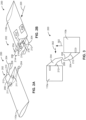
- FIGS. 2A and 2B illustrate an example aircraft coupling apparatus 200 not covered by the appended claims, but of an illustrative nature.
- the first wing 110a of the first aircraft 102a includes a guide 202 (e.g., an alignment device, an alignment contour, an alignment foil, an asymmetric alignment device, etc.) attached thereto.
- the guide 202 of the illustrated example includes two angled and/or curved contoured upper and lower winglets 204 (e.g., contoured winglets, angled winglets, curved winglets, etc.).
- the example winglets 204 each include a distal portion 208 and a base 206.
- the base 206 is attached to the first wing 110a and extends to the distal portion 208.
- the distal portion 208 includes a distal shallow angle portion 210.
- a "shallow" angle can be approximately 0 to 15 degrees in some applications relative to an external surface of the wing 110.
- the base 206 includes a steep angle portion 212.
- a "steep" angle can be approximately 10 to 45 degrees relative to an external surface of the wing 110 in some applications. While example “shallow” and “steep” angles are given, the angles may be implemented at any appropriate range based on application, intended aircraft performance and/or anticipated flight condition(s).
- the first wing 110a also includes openings 211 (e.g., sockets, internal openings, receptacles, etc.).
- the openings 211 may be implemented as recesses or a hole that penetrates an entire component, assembly and/or surface.
- the example guides 202 of the wings 110a, 110b cause the wings 110a, 110b to move toward one another when the guides 202 are brought within a sufficient proximity of one another so that surfaces of the winglets 204 engage one another, thereby guiding movement of the winglets 204 with respect to each other.
- This relative movement of the wings 110a, 110b occurs when the second wing 110b is moved toward the first wing 110a in a direction generally indicated by an arrow 220.
- the shallow angle portions 210 of the opposing distal portions 208 first engage one another and guide movement of the wings 110a, 110b towards one another.
- the corresponding steep angle portions 212 of the respective bases 206 guide final movement of the wings 110a, 110b until the wings are brought into final alignment positions (e.g., the wings 110a, 110b are brought into their final aligned positions).
- the rods 216 are extended into the corresponding openings 211 of the opposing first wing 110a by the actuator 217, thereby preventing relative motion of the wings 110a, 110b.
- the rods 216 are moved into the opening(s) 211 when the sensor 218 of the illustrated example detects sufficient alignment between the wings 110a, 110b and/or the winglets 204.
- the sensor 218 detects alignment of at least one of the rods 216 in relationship to the corresponding opening 211 to determine whether there is sufficient alignment.
- the sensor 218 uses optical markers or other indicators to determine the alignment of the rod(s) 216 to the opening(s) 211.
- each of the wings 110a, 110b includes at least one of the rods 216.
- the wings 110a, 110b extend their respective rods 216 into the corresponding opposed openings 211.
- the example winglets 204 shown in FIGS. 2A and 2B exhibit relatively linear or straight segments in the shallow angle portion 210 and the steep angle portions 212
- the example shallow angle portions 210 and/or the steep angle portions 212 may be instead implemented as multiple arcuate or curved segments.
- shallow angle portions 210 and/or the steep angle portions 212 can exhibit curvature and/or curved transitions therebetween.
- the winglets 204 are rotated by the actuator 217 to further facilitate relative alignment of the winglets 204.
- FIG. 5 is a front/rear view of the example aircraft coupling apparatus 200 of FIGS. 2A, 2B, 3 and 4 shown in the secured condition.
- the relative arrangement of the winglets 204 resembles a general X-shaped intertwining cross pattern when the wings 110a, 110b are secured together.
- the relative arrangement of the winglets 204 can impose little to no drag penalty when the winglets 204 are fully engaged.
- the winglets 204 of the illustrated example not only function to facilitate alignment and securing of the wings 110a, 110b, but can also provide favorable aerodynamic properties when the corresponding aircraft 102a, 102b are secured together.
- any appropriate cross-sectional profile may be implemented, including, but not limited to, a cross-shaped profile, a triangular profile, a star-shaped profile, an irregular or keyed circle profile, a slit profile, a hexagonal-shaped profile, polygonal-shaped profile, etc.
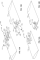
- FIG. 8 is a top schematic view of an aircraft coupling apparatus 800 according to the claimed invention that can be used with the aircraft 102 of FIG. 1 .
- the aircraft coupling apparatus 800 includes paddles 802 (e.g., guide paddles, rotatable paddles) that are disposed within the respective wings 110 of the aircraft 102 and actuators 803 operatively coupled to the respective paddles 802.
- the paddles 802 are asymmetrically arranged relative to a center axis 804 (e.g., a longitudinal center axis) corresponding to the fuselage 104, thereby enabling mechanically robust dual couplings on each of the wings 110.
- the fuselage 104 also includes mid-body landing support flaps 806.
- Each of the paddles 802 of the illustrated example act as a guide and includes a locking portion 810 (e.g., a flat portion, an interlocking portion, an engaging portion, etc.) and a rotatable shaft 812.
- the example locking portion 810, as well as a portion of the rotatable shaft 812, are disposed or stowed within a respective cavity 814 (e.g., a locking cavity, an engaging cavity, a channel) of the wing 110.
- the paddles 802 do not extend out of any external aerodynamic surface of the respective wings 110 during an unsecured condition.
- the paddles 802 of the illustrated example can be moved to extend laterally from the respective wings 110 in directions generally indicated by arrows 816 into another wing 110 of another aircraft 102. Once the paddles 802 have been extended out of their respective wings 110, the example paddles 802 are rotated in a direction generally indicated by arrows 818 to interlock with the other wings 110 to be secured thereto.
- the rotated pattern paddles 802 (shown in the striped pattern) of the illustrated example are shown with the locking portions 810 engaging stops 1004 (e.g., engagement stops, interlocking stops, etc.).
- the stops 1004 are angled and/or contoured to engage the respective locking portions 810.
- the paddles 802 and/or the support flaps 806 define or include wheels (e.g., wheel structures, wheel struts, etc.) or other movement facilitating structures to soften impact of the aircraft 102 when the aircraft lands. Accordingly, movement of the aircraft 102 is facilitated on the ground.
- wheels e.g., wheel structures, wheel struts, etc.
- FIG. 12 is a side cross-sectional view of the landing structure 1100 of FIG. 11 shown in an extended landing position. As can be seen in the illustrated example of FIG. 12 , both of the locking portions 810 of the paddles 802 are rotated to contact the ground. Further, the landing support flaps 806 are also deployed to contact the ground, which may thereby provide a stable support base of the aircraft 102.
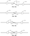
- FIGS. 13A and 13B are perspective views of another example aircraft coupling apparatus 1300 not covered by the appended claims, but of an illustrative nature, that may be used with the aircraft 102 of FIG. 1 .
- a first coupling portion 1302 e.g., a coupling half
- the first coupling portion 1302 includes hooks 1304 (e.g., rotatable hooks).
- Each hook 1304 includes a base 1306 and a distal contact portion 1308 that is substantially perpendicular to the base 1306.
- the first coupling portion 1302 includes openings 1309.
- the openings 1309 are circular and/or round internal openings arranged outward relative to the hooks 1304. In other examples, the openings 1309 may be disposed external to the wing 110a.
- the example hooks 1304 can be caused to move to rotate about an axis 1310 in a direction generally indicated by an arrow 1311 by an actuator 1312, such as a solenoid. In other examples, the hooks 1304 are spring-loaded.
- FIG. 13B illustrates a second coupling portion 1316 of the wing 110b that is configured to couple to the first coupling portion 1302 of the wing 110a (shown in FIG. 13A ).
- the second coupling portion 1316 is configured to engage the first coupling portion 1302 to guide alignment of the wings 110a, 110b and secure the wings 110a, 110b together.
- the second coupling portion 1316 includes a cable 1320 (e.g., a retractable cable) and alignment pins 1324.
- the cable 1320 is restrained at respective attachment joints 1321 (e.g., attachment loops) and extends from a reel 1322 (e.g., a rotatable reel).
- the example cable 1320 defines a number of loops corresponding to the number of hooks 1304 (shown in FIG. 13A ). Accordingly, each loop is configured to engage a respective hook 1304 by at least partially surrounding the respective hook 1304.
- the reel 1322 is disposed within the wing 110b. However, in other examples, the reel 1322 is external to the wing 110b. In other examples, the cable 1320 does not extend from the reel 1322. In such examples, the cable 1320 only loops between the attachment joints 1321 such that a tension and/or length of the cable 1320 is adjusted by a tension adjustment device 1326 (e.g., a loop buckle, a strap-type adjustment mechanism, etc.). In some examples, there is only a single loop defined by the cable 1320 and, thus, only one of the hooks 1304 of the first coupling portion 1302 may be implemented on the wing 110a to be retained by this single loop.
- a tension adjustment device 1326 e.g., a loop buckle, a strap-type adjustment mechanism, etc.
- FIGS. 14A and 14B are perspective views of the example aircraft coupling apparatus 1300 of FIGS. 13A and 13B shown in a secured position.
- the hooks 1304 of the first coupling portion 1302 are rotated away from the distal end of the wing 110a.
- the hooks 1304 are rotated to be disposed within an internal volume of the wing 110a, which may thereby prevent the hooks 1304 from negatively impacting aerodynamic properties during flight.
- both of the aircraft 102a, 102b have been maneuvered so that the distal contact portion 1308 of the hook 1304 engages the cable 1320.
- the cable 1320 is extended outward to form a larger diameter loop(s) to account for positional or orientation mismatch.
- a first guide e.g., the guide 202, the keyed rod 602, the paddle 802, the hook 1304 of a first wing 110a is engaged and/or contacted to a second guide (e.g., the guide 202, the keyed socket 702, the cavity 814, the cable 1320) of a second wing 110b to align the first wing 110a to the second wing 110b (block 1602).
- the first and second aircraft 102a, 102b are brought in close proximity to one another so that engagement between the first and second guides causes movement of the first and second wings 110a, 110b towards one another. Accordingly, the first and second wings 110a, 110b are aligned with each other in order to be secured together.
- first and second aircraft 102a, 102b are secured together to fly together to a mission location in which the first and second aircraft 102a, 102b are to be later separated to perform respective tasks (block 1606). Having the first and second aircraft 102a, 102b secured together in this example increases aerodynamic efficiency by increasing an overall aspect ratio of the wings 110.
- the restraint mechanism 214 (e.g., the lock) is dis-engaged to release the first wing 110a from the second wing 110b (block 1608).
- the first aircraft 102a and the second aircraft 102b can be separated during flight by varying the relative speed(s) of the first and second aircraft 102a, 102b.
- the first and second aircraft 102a, 102b are released from each other to enable the first and second aircraft 102a, 102b to perform their respective tasks, which may be in different locations.
- the first and second aircraft 102a, 102b are caused to have different velocities to facilitate the separation of the first and second aircraft 102a, 102b.
- the first and second aircraft 102a, 102b perform their tasks (e.g., their respective mission(s)) while being separated from one another (block 1610).
- the first and second aircraft 102a, 120b can perform different functions and/or perform operation(s) in different sub-locations (e.g., within the mission location).
- this determination may be based on whether the first and second aircraft 102a, 102b have finished their respective operation(s) in corresponding locations and, thus, should be aligned and secured together again (blocks 1602, 1604), thereby improving overall aerodynamic efficiencies of the first and second aircraft 102, 102b on a return flight. Otherwise, the process ends.
- FIG. 17 is a flowchart representative of an example method 1700 for making the aircraft 102 of FIG. 1 and/or associated components of the aircraft 102 having the coupling apparatus 200, 600, 800, 1300 described in connection with FIGS. 1-15D .
- the example method 1700 of the illustrated example begins as a wing 110 or other outboard structure of an aircraft 102 is provided with components and/or features that enable the aircraft 102 to be secured to other aircraft 102 while the aircraft 102 is hovering and/or is cruising in flight.
- the guide 202 (e.g., the winglets 204) is defined on the wing (block 1702).
- the guide is either assembled to and/or defined within components of the wing.
- the guide 202 may be added as a component to the wing 110 or the wing 110 may be modified to include at least one feature associated with the guide 202 via a manufacturing process (e.g., a sheet metal operation, a bending operation, a cutting operation, etc.).
- the restraint mechanism 214 (e.g., the lock) is defined on the wing 110 (block 1704).
- the restraint mechanism 214 which may include an associated actuator (e.g., the actuator 616, the actuator, the actuator 712, the actuator 803 or the actuator 1312), is placed within an internal volume of the wing 110.
- the restraint mechanism 214 is coupled and/or assembled to the wing 110. In other examples, the restraint mechanism 214 is integral with the wing 110.
- a landing support component(s) is coupled to the lock and/or the guide (block 1706) and the process ends.
- components that facilitate landing or supporting the weight of an associated aircraft are provided to the lock that is used as a landing support.
- the lock can be provided with a wheel and/or a shock dampener to facilitate landing.
- the guide and/or the lock do not require additional features or components to function as landing supports.
- example methods, apparatus and articles of manufacture have been disclosed that enable cost-effective and accurate alignment to secure multiple aircraft together such that wings of these aircraft are in direct contact.
- the examples disclosed herein allow a relatively large continuous aerodynamic surface to be defined for increased aerodynamic efficiency.
- the examples disclosed herein also enable relatively quick alignment of aircraft during flight.
- the examples disclosed herein facilitate alignment even with an initial mismatch.
- Some of the examples disclosed herein also can enable little or no drag penalty based on the geometry of their respective alignment devices and/or restraint mechanisms.
- Some of the examples disclosed herein enable both alignment and securing of wings with a single actuator.
- the examples disclosed herein can enable relatively strong structural connections that may be defined during flight or hovering.
- VTOL vertical take-off and landing
- STOL short take-off and landing
Landscapes
- Engineering & Computer Science (AREA)
- Aviation & Aerospace Engineering (AREA)
- Mechanical Engineering (AREA)
- Remote Sensing (AREA)
- Transportation (AREA)
- Toys (AREA)
- Position Fixing By Use Of Radio Waves (AREA)
- Tires In General (AREA)
- Traffic Control Systems (AREA)
- Aerodynamic Tests, Hydrodynamic Tests, Wind Tunnels, And Water Tanks (AREA)
- Transmission Devices (AREA)
Claims (13)
- Aéronef (102), comprenant :une première aile (110a) ayant un premier guide (202, 602, 802, 1304) ;une deuxième aile (110b) ayant un second guide (202, 702, 814, 1320), les premier et second guides étant configurés pour guider l'aéronef pour être aligné avec un deuxième et un troisième aéronef (102b, 102c), respectivement, durant le vol ou vol stationnaire des aéronefs ;un premier dispositif de verrouillage couplé à la première aile, le premier dispositif de verrouillage étant configuré pour fixer la première aile à une troisième aile (110b) du deuxième aéronef ; etun second dispositif de verrouillage couplé à la deuxième aile, le second dispositif de verrouillage étant configuré pour fixer la deuxième aile à une quatrième aile (110a) du troisième aéronef ;dans lequel les premier et second dispositifs de verrouillage incluent chacun une palette rotative (802) configurée pour être reçue par les troisième et quatrième ailes (110b, 110a), respectivement, et dans lequel chacune des palettes rotatives est configurée pour définir un support d'atterrissage de l'aéronef.
- Aéronef (102) tel que défini dans la revendication 1, dans lequel les premier et second dispositifs de verrouillage sont agencés asymétriquement relativement à un axe longitudinal (804) d'un fuselage (104) de l'aéronef.
- Aéronef (102) tel que défini dans la revendication 1 ou 2, dans lequel chacune des palettes rotatives (802) est configurée pour être mise en rotation pour entrer en prise avec une surface d'une cavité (814) lorsque chacune des palettes (802) est reçue par les troisième ou quatrième ailes respectives (110b, 110a).
- Aéronef de quelconques des revendications 1 à 3, dans lequel chaque dispositif de verrouillage comprend en outre un actionneur (803) fonctionnellement couplé à la palette rotative.
- Aéronef d'une quelconque revendication précédente, dans lequel les palettes (802) sont agencées de façon asymétrique relativement à un axe central correspondant à un fuselage de l'aéronef.
- Aéronef d'une quelconque revendication précédente, dans lequel chaque palette rotative comprend une partie de verrouillage (810) et un arbre rotatif (812).
- Aéronef d'une quelconque revendication précédente, dans lequel les premier et deuxième ailes comprennent chacune une cavité (814).
- Aéronef de la revendication 7, dans lequel chaque cavité comprend une butée d'entrée en prise (1004).
- Aéronef de la revendication 7 ou 8, dans lequel la cavité dans chaque aile est configurée pour escamoter une partie de verrouillage et une partie de l'arbre rotatif de la palette rotative respective.
- Aéronef d'une quelconque revendication précédente, dans lequel chaque palette rotative est configurée pour s'étendre latéralement depuis l'aile respective.
- Aéronef d'une quelconque revendication précédente, dans lequel chaque palette a une forme rectangulaire plate.
- Aéronef de quelconques des revendications 1 à 11, dans lequel chaque palette est profilée, courbée, ou clavetée pour s'aligner et se fixer avec un organe correspondant ou une structure correspondante d'une aile correspondante (110) dans laquelle les palettes (802) sont étendues.
- Procédé (1600) pour fixer un premier aéronef (102a) à un deuxième aéronef (102b), le procédé comprenant :la mise en prise (1602) d'un premier guide (202, 602, 802, 1304) d'une première aile (110a) du premier aéronef avec un second guide (202, 702, 814, 1320) d'une deuxième aile (110b) de la deuxième aéronef, dans lequel la mise en prise du premier guide avec le second guide aligne la première aile avec la deuxième aile ; etla fixation (1604), par l'intermédiaire d'un dispositif de verrouillage, de la première aile à la deuxième aile après que la mise en prise des premier et second guides aligne la première aile avec la deuxième aile, dans lequel la fixation (1604) de la première aile (110a) à la deuxième aile (110b) inclut l'extension d'une palette (802) dans la deuxième aile et la mise en rotation de la palette de telle sorte que la palette entre en contact avec une surface interne d'une cavité (814) de la deuxième aile, dans lequel chacune des palettes rotatives définit un support d'atterrissage de l'aéronef.
Applications Claiming Priority (2)
| Application Number | Priority Date | Filing Date | Title |
|---|---|---|---|
| US15/708,920 US11046434B2 (en) | 2017-09-19 | 2017-09-19 | Methods and apparatus to align and secure aircraft |
| EP18193899.4A EP3459849B1 (fr) | 2017-09-19 | 2018-09-11 | Procédés et appareil pour aligner et fixer un aéronef |
Related Parent Applications (2)
| Application Number | Title | Priority Date | Filing Date |
|---|---|---|---|
| EP18193899.4A Division EP3459849B1 (fr) | 2017-09-19 | 2018-09-11 | Procédés et appareil pour aligner et fixer un aéronef |
| EP18193899.4A Division-Into EP3459849B1 (fr) | 2017-09-19 | 2018-09-11 | Procédés et appareil pour aligner et fixer un aéronef |
Publications (3)
| Publication Number | Publication Date |
|---|---|
| EP4331983A2 EP4331983A2 (fr) | 2024-03-06 |
| EP4331983A3 EP4331983A3 (fr) | 2024-06-05 |
| EP4331983B1 true EP4331983B1 (fr) | 2025-07-02 |
Family
ID=63557385
Family Applications (2)
| Application Number | Title | Priority Date | Filing Date |
|---|---|---|---|
| EP24153278.7A Active EP4331983B1 (fr) | 2017-09-19 | 2018-09-11 | Procédés et appareil pour aligner et sécuriser un aéronef |
| EP18193899.4A Active EP3459849B1 (fr) | 2017-09-19 | 2018-09-11 | Procédés et appareil pour aligner et fixer un aéronef |
Family Applications After (1)
| Application Number | Title | Priority Date | Filing Date |
|---|---|---|---|
| EP18193899.4A Active EP3459849B1 (fr) | 2017-09-19 | 2018-09-11 | Procédés et appareil pour aligner et fixer un aéronef |
Country Status (5)
| Country | Link |
|---|---|
| US (1) | US11046434B2 (fr) |
| EP (2) | EP4331983B1 (fr) |
| JP (1) | JP7176867B2 (fr) |
| CN (1) | CN109515709B (fr) |
| RU (1) | RU2018122086A (fr) |
Families Citing this family (14)
| Publication number | Priority date | Publication date | Assignee | Title |
|---|---|---|---|---|
| US10814973B2 (en) * | 2018-04-18 | 2020-10-27 | Textron Innovations Inc. | Aircraft having M-wing and gull wing configurations |
| US11034447B2 (en) * | 2018-08-31 | 2021-06-15 | Insitu, Inc | Unmanned aerial vehicle (UAV) tethered wing recovery |
| US11724804B2 (en) * | 2019-04-11 | 2023-08-15 | Textron Innovations Inc. | Aircraft coupling mechanism |
| CN120308383A (zh) * | 2019-10-23 | 2025-07-15 | 深圳市道通智能航空技术股份有限公司 | 一种无人飞行器 |
| CN114641431A (zh) * | 2019-11-06 | 2022-06-17 | 株式会社斯巴鲁 | 空陆两用交通工具 |
| USD920216S1 (en) * | 2020-01-03 | 2021-05-25 | Bell Textron Inc. | Combined stator and spindle for a ducted rotor |
| CN111204444B (zh) * | 2020-03-17 | 2025-04-22 | 中国科学院工程热物理研究所 | 组合式无人机的翼尖连接结构 |
| RU2743311C1 (ru) * | 2020-09-15 | 2021-02-17 | Дмитрий Сергеевич Дуров | Модульные самолеты-вертолеты для комплексов арктических ракетно-авиационных |
| RU2753818C1 (ru) * | 2021-02-01 | 2021-08-23 | Дмитрий Сергеевич Дуров | Океаническая система корабельно-авиационная ракетная |
| RU2777132C1 (ru) * | 2021-08-12 | 2022-08-01 | Сергей Павлович Игнатьев | Модульный летательный аппарат и способ его вертикального взлёта |
| CN113716018B (zh) * | 2021-08-24 | 2024-06-11 | 航天时代飞鹏有限公司 | 一种采用3d打印的大载荷机翼 |
| RU2798089C1 (ru) * | 2022-12-28 | 2023-06-15 | Павел Русланович Андреев | Летательный аппарат (варианты), самоходный модуль, полезная нагрузка, система и способ для перемещения полезной нагрузки (варианты) |
| CN116161222B (zh) * | 2023-03-03 | 2025-09-16 | 南京航空航天大学 | 可伸缩的飞行器对接分离机构及其控制方法 |
| EP4585511A1 (fr) * | 2024-01-15 | 2025-07-16 | Seaquenz SL | Aéronef à propulsion électrique |
Family Cites Families (30)
| Publication number | Priority date | Publication date | Assignee | Title |
|---|---|---|---|---|
| US3161373A (en) * | 1949-01-24 | 1964-12-15 | Vogt Richard | Automatic alignment mechanism for composite aircraft |
| US3226056A (en) | 1950-07-12 | 1965-12-28 | Jr Raymond P Holland | Multiple span aircraft |
| US2863618A (en) | 1954-04-29 | 1958-12-09 | Republic Aviat Corp | Airplane coupling means |
| US2809792A (en) | 1955-05-23 | 1957-10-15 | Bernhard A Hohmann | Coupling apparatus for fighter aircraft |
| US3249322A (en) | 1964-04-06 | 1966-05-03 | Jr Raymond Prunty Holland | Air train |
| US6641082B2 (en) * | 2002-04-01 | 2003-11-04 | Lockheed Martin Corporation | Aircraft ferrying system and method thereof |
| DE102004026816A1 (de) * | 2004-06-02 | 2006-01-05 | Reinhardt, Gaby Traute | Luftfrachttransportverfahren, Transportflugzeug sowie Luftfrachttransportsystem |
| US7789339B2 (en) * | 2005-07-07 | 2010-09-07 | Sommer Geoffrey S | Modular articulated-wing aircraft |
| US8544800B2 (en) * | 2005-07-21 | 2013-10-01 | The Boeing Company | Integrated wingtip extensions for jet transport aircraft and other types of aircraft |
| US7357352B2 (en) | 2005-11-09 | 2008-04-15 | The Boeing Company | Air vehicle assembly and an associated control system and method |
| US8061646B2 (en) * | 2007-09-14 | 2011-11-22 | Aurora Flight Sciences Corporation | Wing tip docking system for aircraft |
| DE102008020654B4 (de) * | 2008-04-24 | 2018-10-04 | Airbus Operations Gmbh | Tragflügel und Flugzeug mit einer Lateral-Kopplungsvorrichtung |
| US9043052B2 (en) | 2008-05-27 | 2015-05-26 | Wilfred So | System and method for multiple vehicles moving a common payload |
| JP5134469B2 (ja) | 2008-08-21 | 2013-01-30 | 三菱重工業株式会社 | 無人機システム及びその運用方法 |
| JP5501690B2 (ja) * | 2009-07-31 | 2014-05-28 | 三菱重工業株式会社 | 発射システム及び発射装置 |
| US8936212B1 (en) * | 2009-08-25 | 2015-01-20 | Qiang Fu | System and method for compact and combinable aerial vehicle capable of vertical/short takeoff and landing |
| EP2509862B1 (fr) * | 2009-12-10 | 2016-05-04 | University Of The Witwatersrand, Johannesburg | Ailette de bout d'aile d'aeronef et procede pour son operation |
| WO2012141736A1 (fr) * | 2010-10-06 | 2012-10-18 | Shaw Donlad Orval | Aéronef comportant des ailes et des hélices mobiles |
| US8632031B2 (en) * | 2011-04-11 | 2014-01-21 | The Boeing Company | Systems and methods for attenuation of noise and wakes produced by aircraft |
| US8936219B2 (en) * | 2012-03-30 | 2015-01-20 | The Boeing Company | Performance-enhancing winglet system and method |
| GB201209697D0 (en) * | 2012-05-31 | 2012-07-18 | Airbus Uk Ltd | Method of coupling aerofoil surface structures and an aerofoil assembly |
| WO2014039636A1 (fr) * | 2012-09-05 | 2014-03-13 | V Cirrus Winglet Group, Llc | Ailettes à biseaux multiples |
| NL2009762C2 (en) * | 2012-11-06 | 2014-05-08 | Fokker Aerostructures Bv | An airplane wing, airplane and flap system. |
| GB201301680D0 (en) * | 2013-01-31 | 2013-03-13 | Airbus Uk Ltd | Downwardly extending wing tip device |
| CA2829368A1 (fr) | 2013-10-08 | 2015-04-08 | Shelton G. De Silva | Combinaison de vehicules aeriens sans pilote et procede et systeme pour participer a de multiples applications |
| US10562613B2 (en) * | 2013-12-04 | 2020-02-18 | Tamarack Aerospace Group, Inc. | Adjustable lift modification wingtip |
| US20160244147A1 (en) * | 2015-02-20 | 2016-08-25 | Northrop Grumman Systems Corporation | Quiet slat propeller |
| US10059428B2 (en) * | 2016-08-10 | 2018-08-28 | Bell Helicopter Textron Inc. | Inflight connection of aircraft |
| CN206407109U (zh) * | 2016-12-26 | 2017-08-15 | 昊翔电能运动科技(昆山)有限公司 | 旋翼无人机及机翼桨叶组件 |
| CN106927022B (zh) * | 2017-03-23 | 2023-08-15 | 清华大学 | 基于自展开折叠翼技术的超大展弦比飞机 |
-
2017
- 2017-09-19 US US15/708,920 patent/US11046434B2/en active Active
-
2018
- 2018-06-15 JP JP2018114426A patent/JP7176867B2/ja active Active
- 2018-06-18 RU RU2018122086A patent/RU2018122086A/ru unknown
- 2018-09-11 EP EP24153278.7A patent/EP4331983B1/fr active Active
- 2018-09-11 EP EP18193899.4A patent/EP3459849B1/fr active Active
- 2018-09-12 CN CN201811065502.7A patent/CN109515709B/zh active Active
Also Published As
| Publication number | Publication date |
|---|---|
| RU2018122086A (ru) | 2019-12-18 |
| US11046434B2 (en) | 2021-06-29 |
| RU2018122086A3 (fr) | 2021-12-23 |
| EP4331983A3 (fr) | 2024-06-05 |
| US20190084664A1 (en) | 2019-03-21 |
| JP2019055766A (ja) | 2019-04-11 |
| CN109515709A (zh) | 2019-03-26 |
| EP3459849B1 (fr) | 2024-02-28 |
| JP7176867B2 (ja) | 2022-11-22 |
| EP4331983A2 (fr) | 2024-03-06 |
| EP3459849A1 (fr) | 2019-03-27 |
| CN109515709B (zh) | 2023-07-07 |
Similar Documents
| Publication | Publication Date | Title |
|---|---|---|
| EP4331983B1 (fr) | Procédés et appareil pour aligner et sécuriser un aéronef | |
| US10293933B2 (en) | Rotating wing assemblies for tailsitter aircraft | |
| US10710702B2 (en) | Shape adaptive airfoil | |
| CN106163919B (zh) | 包括可折叠空气动力学结构的飞行器及制造用于飞行器的可折叠空气动力学结构的方法 | |
| EP3038913B1 (fr) | Véhicule aérien pour décollage et atterrissage vertical | |
| US7334755B2 (en) | Tandem rotor wing and tandem fixed wing aircraft | |
| EP1114772B1 (fr) | Aéronef VTOL avec des ailes à flèche variable | |
| US20120292436A1 (en) | Compact aircraft wing folding systems and methods | |
| US20170021924A1 (en) | Control system and strategy for tail sitter | |
| EP2874873B1 (fr) | Configuration d'aéronef résistant à la vrille | |
| US11912435B2 (en) | Air vehicle system | |
| EP3587261B1 (fr) | Aéronef à aile volante | |
| US10272999B2 (en) | Tail-sitter aircraft with legged undercarriage foldable to form rear fuselage | |
| CN110979711B (zh) | 用于回收旋翼飞行器的方法和装置 | |
| CN108082471B (zh) | 一种变体超音速飞机 | |
| CN114945509B (zh) | 包括中央翼和两个可旋转侧翼的电动推进飞行器 | |
| US8590831B2 (en) | Flying vehicle | |
| US12162592B2 (en) | Aircraft with pivotally connected wing and rotor | |
| EP2933185B1 (fr) | Aéronef avec un système de ravitaillement en vol pour aile | |
| EP4168307B1 (fr) | Module d'aile pour véhicule aérien | |
| AU2021475016C1 (en) | Airborne recovery of unmanned aerial vehicles | |
| CN119734822A (zh) | 采用可折叠机翼的尾座式无尾布局两栖飞行器及设计方法 | |
| RU2828443C1 (ru) | Центроплан крыла беспилотного воздушного судна самолетного типа с вертикальным взлетом и посадкой (vtol) | |
| EP4554854A1 (fr) | Aéronef à décollage vertical | |
| CN121404583A (zh) | 一种垂直起降固定翼无人机及工作方法 |
Legal Events
| Date | Code | Title | Description |
|---|---|---|---|
| PUAI | Public reference made under article 153(3) epc to a published international application that has entered the european phase |
Free format text: ORIGINAL CODE: 0009012 |
|
| STAA | Information on the status of an ep patent application or granted ep patent |
Free format text: STATUS: THE APPLICATION HAS BEEN PUBLISHED |
|
| AC | Divisional application: reference to earlier application |
Ref document number: 3459849 Country of ref document: EP Kind code of ref document: P |
|
| AK | Designated contracting states |
Kind code of ref document: A2 Designated state(s): AL AT BE BG CH CY CZ DE DK EE ES FI FR GB GR HR HU IE IS IT LI LT LU LV MC MK MT NL NO PL PT RO RS SE SI SK SM TR |
|
| REG | Reference to a national code |
Ref country code: DE Ref legal event code: R079 Free format text: PREVIOUS MAIN CLASS: B64C0039020000 Ipc: B64C0037020000 Ref document number: 602018083359 Country of ref document: DE |
|
| PUAL | Search report despatched |
Free format text: ORIGINAL CODE: 0009013 |
|
| AK | Designated contracting states |
Kind code of ref document: A3 Designated state(s): AL AT BE BG CH CY CZ DE DK EE ES FI FR GB GR HR HU IE IS IT LI LT LU LV MC MK MT NL NO PL PT RO RS SE SI SK SM TR |
|
| RIC1 | Information provided on ipc code assigned before grant |
Ipc: B64D 39/00 20060101ALN20240429BHEP Ipc: B64C 39/02 20230101ALI20240429BHEP Ipc: B64C 37/02 20060101AFI20240429BHEP |
|
| STAA | Information on the status of an ep patent application or granted ep patent |
Free format text: STATUS: REQUEST FOR EXAMINATION WAS MADE |
|
| 17P | Request for examination filed |
Effective date: 20241126 |
|
| RBV | Designated contracting states (corrected) |
Designated state(s): AL AT BE BG CH CY CZ DE DK EE ES FI FR GB GR HR HU IE IS IT LI LT LU LV MC MK MT NL NO PL PT RO RS SE SI SK SM TR |
|
| GRAP | Despatch of communication of intention to grant a patent |
Free format text: ORIGINAL CODE: EPIDOSNIGR1 |
|
| STAA | Information on the status of an ep patent application or granted ep patent |
Free format text: STATUS: GRANT OF PATENT IS INTENDED |
|
| RIC1 | Information provided on ipc code assigned before grant |
Ipc: B64D 39/00 20060101ALN20250114BHEP Ipc: B64C 39/02 20230101ALI20250114BHEP Ipc: B64C 37/02 20060101AFI20250114BHEP |
|
| INTG | Intention to grant announced |
Effective date: 20250128 |
|
| GRAS | Grant fee paid |
Free format text: ORIGINAL CODE: EPIDOSNIGR3 |
|
| GRAA | (expected) grant |
Free format text: ORIGINAL CODE: 0009210 |
|
| STAA | Information on the status of an ep patent application or granted ep patent |
Free format text: STATUS: THE PATENT HAS BEEN GRANTED |
|
| P01 | Opt-out of the competence of the unified patent court (upc) registered |
Free format text: CASE NUMBER: APP_21134/2025 Effective date: 20250505 |
|
| AC | Divisional application: reference to earlier application |
Ref document number: 3459849 Country of ref document: EP Kind code of ref document: P |
|
| AK | Designated contracting states |
Kind code of ref document: B1 Designated state(s): AL AT BE BG CH CY CZ DE DK EE ES FI FR GB GR HR HU IE IS IT LI LT LU LV MC MK MT NL NO PL PT RO RS SE SI SK SM TR |
|
| REG | Reference to a national code |
Ref country code: GB Ref legal event code: FG4D |
|
| REG | Reference to a national code |
Ref country code: CH Ref legal event code: EP |
|
| REG | Reference to a national code |
Ref country code: DE Ref legal event code: R096 Ref document number: 602018083359 Country of ref document: DE |
|
| REG | Reference to a national code |
Ref country code: IE Ref legal event code: FG4D |
|
| PGFP | Annual fee paid to national office [announced via postgrant information from national office to epo] |
Ref country code: DE Payment date: 20250929 Year of fee payment: 8 |
|
| PGFP | Annual fee paid to national office [announced via postgrant information from national office to epo] |
Ref country code: GB Payment date: 20250929 Year of fee payment: 8 |
|
| PGFP | Annual fee paid to national office [announced via postgrant information from national office to epo] |
Ref country code: FR Payment date: 20250925 Year of fee payment: 8 |
|
| PG25 | Lapsed in a contracting state [announced via postgrant information from national office to epo] |
Ref country code: PT Free format text: LAPSE BECAUSE OF FAILURE TO SUBMIT A TRANSLATION OF THE DESCRIPTION OR TO PAY THE FEE WITHIN THE PRESCRIBED TIME-LIMIT Effective date: 20251103 |
|
| PG25 | Lapsed in a contracting state [announced via postgrant information from national office to epo] |
Ref country code: NL Free format text: LAPSE BECAUSE OF FAILURE TO SUBMIT A TRANSLATION OF THE DESCRIPTION OR TO PAY THE FEE WITHIN THE PRESCRIBED TIME-LIMIT Effective date: 20250702 |
|
| REG | Reference to a national code |
Ref country code: AT Ref legal event code: MK05 Ref document number: 1808982 Country of ref document: AT Kind code of ref document: T Effective date: 20250702 |
|
| PG25 | Lapsed in a contracting state [announced via postgrant information from national office to epo] |
Ref country code: IS Free format text: LAPSE BECAUSE OF FAILURE TO SUBMIT A TRANSLATION OF THE DESCRIPTION OR TO PAY THE FEE WITHIN THE PRESCRIBED TIME-LIMIT Effective date: 20251102 |
|
| PG25 | Lapsed in a contracting state [announced via postgrant information from national office to epo] |
Ref country code: NO Free format text: LAPSE BECAUSE OF FAILURE TO SUBMIT A TRANSLATION OF THE DESCRIPTION OR TO PAY THE FEE WITHIN THE PRESCRIBED TIME-LIMIT Effective date: 20251002 |
|
| REG | Reference to a national code |
Ref country code: LT Ref legal event code: MG9D |
|
| PG25 | Lapsed in a contracting state [announced via postgrant information from national office to epo] |
Ref country code: AT Free format text: LAPSE BECAUSE OF FAILURE TO SUBMIT A TRANSLATION OF THE DESCRIPTION OR TO PAY THE FEE WITHIN THE PRESCRIBED TIME-LIMIT Effective date: 20250702 |
|
| PG25 | Lapsed in a contracting state [announced via postgrant information from national office to epo] |
Ref country code: FI Free format text: LAPSE BECAUSE OF FAILURE TO SUBMIT A TRANSLATION OF THE DESCRIPTION OR TO PAY THE FEE WITHIN THE PRESCRIBED TIME-LIMIT Effective date: 20250702 |
|
| PG25 | Lapsed in a contracting state [announced via postgrant information from national office to epo] |
Ref country code: HR Free format text: LAPSE BECAUSE OF FAILURE TO SUBMIT A TRANSLATION OF THE DESCRIPTION OR TO PAY THE FEE WITHIN THE PRESCRIBED TIME-LIMIT Effective date: 20250702 |
|
| PG25 | Lapsed in a contracting state [announced via postgrant information from national office to epo] |
Ref country code: GR Free format text: LAPSE BECAUSE OF FAILURE TO SUBMIT A TRANSLATION OF THE DESCRIPTION OR TO PAY THE FEE WITHIN THE PRESCRIBED TIME-LIMIT Effective date: 20251003 |
|
| PG25 | Lapsed in a contracting state [announced via postgrant information from national office to epo] |
Ref country code: SE Free format text: LAPSE BECAUSE OF FAILURE TO SUBMIT A TRANSLATION OF THE DESCRIPTION OR TO PAY THE FEE WITHIN THE PRESCRIBED TIME-LIMIT Effective date: 20250702 Ref country code: CZ Free format text: LAPSE BECAUSE OF FAILURE TO SUBMIT A TRANSLATION OF THE DESCRIPTION OR TO PAY THE FEE WITHIN THE PRESCRIBED TIME-LIMIT Effective date: 20250702 |
|
| PG25 | Lapsed in a contracting state [announced via postgrant information from national office to epo] |
Ref country code: LV Free format text: LAPSE BECAUSE OF FAILURE TO SUBMIT A TRANSLATION OF THE DESCRIPTION OR TO PAY THE FEE WITHIN THE PRESCRIBED TIME-LIMIT Effective date: 20250702 |
|
| PG25 | Lapsed in a contracting state [announced via postgrant information from national office to epo] |
Ref country code: PL Free format text: LAPSE BECAUSE OF FAILURE TO SUBMIT A TRANSLATION OF THE DESCRIPTION OR TO PAY THE FEE WITHIN THE PRESCRIBED TIME-LIMIT Effective date: 20250702 Ref country code: BG Free format text: LAPSE BECAUSE OF FAILURE TO SUBMIT A TRANSLATION OF THE DESCRIPTION OR TO PAY THE FEE WITHIN THE PRESCRIBED TIME-LIMIT Effective date: 20250702 |
|
| PG25 | Lapsed in a contracting state [announced via postgrant information from national office to epo] |
Ref country code: RS Free format text: LAPSE BECAUSE OF FAILURE TO SUBMIT A TRANSLATION OF THE DESCRIPTION OR TO PAY THE FEE WITHIN THE PRESCRIBED TIME-LIMIT Effective date: 20251002 |
|
| PG25 | Lapsed in a contracting state [announced via postgrant information from national office to epo] |
Ref country code: ES Free format text: LAPSE BECAUSE OF FAILURE TO SUBMIT A TRANSLATION OF THE DESCRIPTION OR TO PAY THE FEE WITHIN THE PRESCRIBED TIME-LIMIT Effective date: 20250702 |
|
| PG25 | Lapsed in a contracting state [announced via postgrant information from national office to epo] |
Ref country code: RO Free format text: LAPSE BECAUSE OF FAILURE TO SUBMIT A TRANSLATION OF THE DESCRIPTION OR TO PAY THE FEE WITHIN THE PRESCRIBED TIME-LIMIT Effective date: 20250702 |
|
| PG25 | Lapsed in a contracting state [announced via postgrant information from national office to epo] |
Ref country code: SM Free format text: LAPSE BECAUSE OF FAILURE TO SUBMIT A TRANSLATION OF THE DESCRIPTION OR TO PAY THE FEE WITHIN THE PRESCRIBED TIME-LIMIT Effective date: 20250702 |
|
| PG25 | Lapsed in a contracting state [announced via postgrant information from national office to epo] |
Ref country code: DK Free format text: LAPSE BECAUSE OF FAILURE TO SUBMIT A TRANSLATION OF THE DESCRIPTION OR TO PAY THE FEE WITHIN THE PRESCRIBED TIME-LIMIT Effective date: 20250702 |
|
| PG25 | Lapsed in a contracting state [announced via postgrant information from national office to epo] |
Ref country code: IT Free format text: LAPSE BECAUSE OF FAILURE TO SUBMIT A TRANSLATION OF THE DESCRIPTION OR TO PAY THE FEE WITHIN THE PRESCRIBED TIME-LIMIT Effective date: 20250702 |
|
| PG25 | Lapsed in a contracting state [announced via postgrant information from national office to epo] |
Ref country code: EE Free format text: LAPSE BECAUSE OF FAILURE TO SUBMIT A TRANSLATION OF THE DESCRIPTION OR TO PAY THE FEE WITHIN THE PRESCRIBED TIME-LIMIT Effective date: 20250702 Ref country code: SK Free format text: LAPSE BECAUSE OF FAILURE TO SUBMIT A TRANSLATION OF THE DESCRIPTION OR TO PAY THE FEE WITHIN THE PRESCRIBED TIME-LIMIT Effective date: 20250702 |