EP4331987A1 - Monument de cabine et aéronef - Google Patents
Monument de cabine et aéronef Download PDFInfo
- Publication number
- EP4331987A1 EP4331987A1 EP22192739.5A EP22192739A EP4331987A1 EP 4331987 A1 EP4331987 A1 EP 4331987A1 EP 22192739 A EP22192739 A EP 22192739A EP 4331987 A1 EP4331987 A1 EP 4331987A1
- Authority
- EP
- European Patent Office
- Prior art keywords
- cabin
- monument
- light
- aircraft
- emitting elements
- Prior art date
- Legal status (The legal status is an assumption and is not a legal conclusion. Google has not performed a legal analysis and makes no representation as to the accuracy of the status listed.)
- Granted
Links
Images


Classifications
-
- B—PERFORMING OPERATIONS; TRANSPORTING
- B64—AIRCRAFT; AVIATION; COSMONAUTICS
- B64D—EQUIPMENT FOR FITTING IN OR TO AIRCRAFT; FLIGHT SUITS; PARACHUTES; ARRANGEMENT OR MOUNTING OF POWER PLANTS OR PROPULSION TRANSMISSIONS IN AIRCRAFT
- B64D11/00—Passenger or crew accommodation; Flight-deck installations not otherwise provided for
- B64D11/0015—Arrangements for entertainment or communications, e.g. radio, television
-
- B—PERFORMING OPERATIONS; TRANSPORTING
- B64—AIRCRAFT; AVIATION; COSMONAUTICS
- B64D—EQUIPMENT FOR FITTING IN OR TO AIRCRAFT; FLIGHT SUITS; PARACHUTES; ARRANGEMENT OR MOUNTING OF POWER PLANTS OR PROPULSION TRANSMISSIONS IN AIRCRAFT
- B64D11/00—Passenger or crew accommodation; Flight-deck installations not otherwise provided for
- B64D11/003—Stowage devices for passengers' personal luggage
-
- B—PERFORMING OPERATIONS; TRANSPORTING
- B64—AIRCRAFT; AVIATION; COSMONAUTICS
- B64D—EQUIPMENT FOR FITTING IN OR TO AIRCRAFT; FLIGHT SUITS; PARACHUTES; ARRANGEMENT OR MOUNTING OF POWER PLANTS OR PROPULSION TRANSMISSIONS IN AIRCRAFT
- B64D11/00—Passenger or crew accommodation; Flight-deck installations not otherwise provided for
- B64D11/02—Toilet fittings
-
- B—PERFORMING OPERATIONS; TRANSPORTING
- B64—AIRCRAFT; AVIATION; COSMONAUTICS
- B64D—EQUIPMENT FOR FITTING IN OR TO AIRCRAFT; FLIGHT SUITS; PARACHUTES; ARRANGEMENT OR MOUNTING OF POWER PLANTS OR PROPULSION TRANSMISSIONS IN AIRCRAFT
- B64D11/00—Passenger or crew accommodation; Flight-deck installations not otherwise provided for
- B64D11/04—Galleys
-
- B—PERFORMING OPERATIONS; TRANSPORTING
- B64—AIRCRAFT; AVIATION; COSMONAUTICS
- B64D—EQUIPMENT FOR FITTING IN OR TO AIRCRAFT; FLIGHT SUITS; PARACHUTES; ARRANGEMENT OR MOUNTING OF POWER PLANTS OR PROPULSION TRANSMISSIONS IN AIRCRAFT
- B64D11/00—Passenger or crew accommodation; Flight-deck installations not otherwise provided for
- B64D11/0023—Movable or removable cabin dividers, e.g. for class separation
-
- B—PERFORMING OPERATIONS; TRANSPORTING
- B64—AIRCRAFT; AVIATION; COSMONAUTICS
- B64D—EQUIPMENT FOR FITTING IN OR TO AIRCRAFT; FLIGHT SUITS; PARACHUTES; ARRANGEMENT OR MOUNTING OF POWER PLANTS OR PROPULSION TRANSMISSIONS IN AIRCRAFT
- B64D11/00—Passenger or crew accommodation; Flight-deck installations not otherwise provided for
- B64D2011/0038—Illumination systems for cabins as a whole
Definitions
- the present invention relates to a cabin monument and an aircraft.
- a cabin monument is understood to be any component that is arranged within the cabin of an aircraft.
- these can be cabin partitions, seat assemblies or even storage spaces for hand luggage.
- These screens are used both to display important information, such as security-related information, and to play entertainment media.
- Each screen provided in this way contributes to the overall weight of the aircraft, which should be kept as low as possible for many reasons, for example with regard to fuel consumption.
- screens also contribute to the energy consumption of the aircraft, which should also be kept as low as possible.
- An inactive screen appears black to the viewer and contrasts with the mostly brightly designed cabin monuments, which can be perceived as unpleasant by passengers.
- the present invention is based on the object of reducing the weight and energy requirements of screens in an aircraft and at the same time avoiding visual effects that are perceived as unpleasant.
- a cabin monument is provided.
- a cabin monument can be, for example, an aircraft galley, an aircraft toilet, a storage facility or a partition wall.
- the cabin monument includes a monument body and a transparent film connected to the monument body.
- the transparent film has a large number of light-emitting elements.
- the aircraft comprises at least one cabin monument according to the invention and a control device which is designed to control the plurality of light-emitting elements of the at least one cabin monument.
- the idea underlying the present invention is to use light-emitting elements embedded in a transparent film as "pixels" of a screen for a cabin monument. Accordingly, weight can be saved compared to conventional screens because the transparent film is very thin and therefore lightweight, while when the light-emitting elements are inactive, the overall visual impression of the cabin monument remains unchanged due to the transparency of the film.
- the light-emitting elements can be designed as light-emitting diodes. This allows the light-emitting elements to be made particularly small, light and energy-efficient.
- the transparent film can be attached to a surface of the monument body. This enables particularly easy production or even retrofitting of existing cabin monuments.
- the cabin monument can also have a transparent protective coating. This can advantageously protect the transparent film from damage.
- the monument body can have a continuously transparent area, with the transparent film at least partially overlapping the transparent area. This makes it possible to see through the cabin monument, for example in the form of a cabin partition, in certain situations and not in other situations.
- the light-emitting elements can be arranged such that light is emitted through the transparent area. This allows the film to be applied where there is as little interaction as possible with the environment, for example with passengers, which can protect the film from damage.
- the cabin monument can be designed as a seat component or cabin partition wall.
- screens can fulfill a variety of advantageous functions, as will be explained in detail later.
- control device can be designed to control the light-emitting elements of the at least one cabin monument depending on an operating state of the aircraft.
- the energy consumption of the light-emitting elements can advantageously be regulated precisely.
- the operating state of the aircraft can include a take-off process or a landing process, during which the light-emitting elements are controlled in such a way that light is emitted.
- the aircraft can have at least two cabin monuments, the control device being designed to control the light-emitting elements of the at least two cabin monuments in coordination with one another. In this way, a particularly advantageous, harmonious, overall visual impression of the cabin of the aircraft can be achieved.
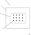
- Fig. 1 shows a schematic representation of a cabin monument 10 according to a preferred embodiment of the present invention.
- the cabin monument 10 has a monument body 11 and a transparent film 12 connected to this monument body 11.
- the transparent film 12 has a large number of light-emitting elements 13.
- the in Figure 1 Monument body 11 shown is represented, for example, by a square.
- the monument body 11 can take on any conceivable shape, depending on the function that the cabin monument 10 is intended to fulfill.
- the monument body 11 can also be assembled from a large number of separate individual parts.
- the transparency of the film 12 is in Figure 1 indicated by the use of a dashed outline.
- “transparent” means that a human viewer can perceive the monument body 11 from a distance of a few centimeters or further through the transparent film 12 without the transparent film influencing the overall visual impression of the monument body 11. This is particularly true in situations in which the light-emitting elements 13 do not emit any light. In situations in which the light-emitting elements 13 emit light, the overall visual impression for a viewer can certainly be influenced, for example by giving the viewer a pictorial representation through the overall view of the light emitted by all light-emitting elements 13.
- the transparent film 12 is shown as being attached to a surface of the monument body 11.
- the transparent film 12 can also be integrated into the monument body 11, especially if the monument body 11 consists of several components.
- an outer shell of a monument body 11 can consist of several plastic layers laminated on one another.
- the transparent film 12 can be embedded between two of these layers if the layers between the film and the surface are transparent.
- the cabin monument 10 can also have a transparent protective coating.
- FIG. 1 A total of twelve light-emitting elements 13 are shown, which are arranged in a regular grid over the surface of the transparent film 12.
- any number of light-emitting elements 13 can be provided, in particular enough so that when each light-emitting element 13 acts as a "pixel", a sufficiently well-resolved image can be displayed.
- the light-emitting elements 13 are shown to be relatively large compared to the extent of the monument body 11 and the transparent film 12. In a real embodiment of the cabin monument 10, however, the light-emitting elements 13 can be of any size, in particular, such a size that they are no longer visible to the human eye from a distance of a few centimeters.
- Fig. 2 shows a schematic representation of an aircraft 100 according to an exemplary embodiment of the invention.
- the aircraft 100 has a cabin monument 10 and a control device 20.
- the cabin monument 10 has a monument body 11 and a transparent film 12.
- the transparent film 12 has a large number of light-emitting elements, which for reasons of clarity Figure 2 not be shown.
- Fig. 3 shows a schematic representation of a section of an aircraft 100 according to an embodiment of the present invention.
- the aircraft 100 has a first cabin monument 10a, a plurality of second cabin monuments 10b, and a control device 20.
- the first cabin monument 10a and the second cabin monument 10b each have a monument body 11a, 11b and a transparent film 12a, 12b.
- the first cabin monument 10a also has a continuously transparent area 14a, with the transparent film 12a of the first cabin monument 10a partially overlapping the transparent area 14a.
- the control device 20 is connected to the cabin monuments 10a, 10b and is designed to control their light-emitting To control elements, although this connection is not shown explicitly for reasons of clarity.
- the first cabin monument 10a is designed as a cabin partition wall, which divides the aircraft 100 into two areas.
- the second cabin monuments 10b are designed as seat assemblies and are arranged only in one of the two areas of the aircraft. This results in an area in which passengers stay in the seat assemblies during the flight and an area which is reserved for the cabin crew.
- the transparent film 12a of the first cabin monument 10a is attached to the side of the cabin partition wall facing the area intended for the cabin crew.
- the light-emitting elements of the first cabin monument 10a can be designed in such a way that the light emitted by them is emitted through the transparent area 14a of the first cabin monument 10a into the area of the aircraft intended for the passengers. This results in a type of one-sided transparency in which the cabin crew can see through the transparent area 14a into the passenger area, but the passengers cannot see into the crew area. This can allow the cabin crew to monitor the passenger area, for example during take-off or landing, without being observed by the passengers themselves.
- the light-emitting elements of the first cabin monument 10a can also be arranged such that they emit light into the crew area. In this case, the emission of light can be switched off in situations in which the cabin crew is supposed to monitor the passenger area and the light emitting ones Elements can be used in other situations to display useful information to the cabin crew.
- a combination of these two variants is also conceivable, either with a transparent film which has light-emitting elements which can emit light in both directions, or with two transparent films arranged one above the other or adjacently.
- the transparent films 12b of the second cabin monuments 10b are each attached to the backs of the monument bodies 11b and can thus serve as screens for the passengers on the seating groups arranged at the rear.
- the light-emitting elements of the second cabin monuments 10b may or may not emit light.
- the light-emitting elements could display safety-relevant information during a take-off or landing process and not emit any light during the flight, without the passengers noticing the flight via a switched-off screen in their field of vision that is perceived as disturbing.
- the light-emitting elements can be switched off during a take-off or landing process in order not to distract the passenger's attention from instructions from the cabin crew and then serve as a screen during the flight, for example for playing entertainment media.
- the control device 20 is designed to control the light-emitting elements of the cabin monuments 10a, 10b. This control can be carried out for each cabin monument 10a, 10b, independently or coordinated with one another. If the light-emitting elements of the second cabin monuments 10b are to be used, for example, for playing entertainment media, each of the second cabin monuments 10b can be controlled independently of one another. In other situations it may be advantageous to use the light emitting ones Elements of the second cabin monuments 10b must be controlled in a coordinated manner in order to create the most harmonious overall visual impression of the cabin.
Landscapes
- Engineering & Computer Science (AREA)
- Aviation & Aerospace Engineering (AREA)
- Illuminated Signs And Luminous Advertising (AREA)
Priority Applications (3)
| Application Number | Priority Date | Filing Date | Title |
|---|---|---|---|
| EP22192739.5A EP4331987B1 (fr) | 2022-08-30 | 2022-08-30 | Monument de cabine et aéronef |
| US18/457,103 US12497172B2 (en) | 2022-08-30 | 2023-08-28 | Cabin monument and aircraft |
| CN202311094568.XA CN117622490A (zh) | 2022-08-30 | 2023-08-28 | 机舱模块和飞机 |
Applications Claiming Priority (1)
| Application Number | Priority Date | Filing Date | Title |
|---|---|---|---|
| EP22192739.5A EP4331987B1 (fr) | 2022-08-30 | 2022-08-30 | Monument de cabine et aéronef |
Publications (2)
| Publication Number | Publication Date |
|---|---|
| EP4331987A1 true EP4331987A1 (fr) | 2024-03-06 |
| EP4331987B1 EP4331987B1 (fr) | 2025-12-17 |
Family
ID=83152058
Family Applications (1)
| Application Number | Title | Priority Date | Filing Date |
|---|---|---|---|
| EP22192739.5A Active EP4331987B1 (fr) | 2022-08-30 | 2022-08-30 | Monument de cabine et aéronef |
Country Status (3)
| Country | Link |
|---|---|
| US (1) | US12497172B2 (fr) |
| EP (1) | EP4331987B1 (fr) |
| CN (1) | CN117622490A (fr) |
Citations (9)
| Publication number | Priority date | Publication date | Assignee | Title |
|---|---|---|---|---|
| US20060228558A1 (en) * | 2005-04-08 | 2006-10-12 | Berry Craig L | Layered, transparent thermoplastic for flammability resistance |
| US20090224103A1 (en) * | 2008-02-27 | 2009-09-10 | Airbus Deutschland Gmbh | Partition wall in an aircraft |
| US20130016525A1 (en) * | 2010-02-04 | 2013-01-17 | Airbus Operations Gmbh | Flat illuminating display device and light-emitting means therefor |
| US20150274068A1 (en) * | 2014-03-27 | 2015-10-01 | Carlos D. Falconi | Illuminated Seat Cover Assembly |
| EP3378785A1 (fr) * | 2017-03-24 | 2018-09-26 | The Boeing Company | Système et méthode de tapis écran |
| EP3546356A1 (fr) * | 2018-04-01 | 2019-10-02 | The Boeing Company | Véhicule doté d'un élément de fenêtre simulé |
| EP3552964A1 (fr) * | 2018-04-10 | 2019-10-16 | Rockwell Collins, Inc. | Panneau lumineux micro-led intégré d'aéronef |
| US20200130839A1 (en) * | 2018-10-30 | 2020-04-30 | Airbus Operations Gmbh | Panelling Part For A Cabin Of A Means Of Transportation |
| US20220055751A1 (en) * | 2020-08-19 | 2022-02-24 | B/E Aerospace, Inc. | Integrated aircraft seat control panel |
Family Cites Families (10)
| Publication number | Priority date | Publication date | Assignee | Title |
|---|---|---|---|---|
| DE102006007285A1 (de) * | 2006-02-16 | 2007-08-30 | Airbus Deutschland Gmbh | Visualisierungssystem in einem Flugzeug |
| DE102009029874A1 (de) * | 2009-06-22 | 2010-12-23 | Airbus Operations Gmbh | Beleuchtungsvorrichtung mit einer Mehrzahl von Lichtquellen |
| US9254918B2 (en) * | 2012-12-11 | 2016-02-09 | C&D Zodiac, Inc. | Aircraft aisle partition with swinging doors |
| US20140175219A1 (en) * | 2012-12-11 | 2014-06-26 | C&D Zodiac, Inc. | Fixed aircraft aisle partition with lighting |
| DE102013207062A1 (de) * | 2013-04-18 | 2014-10-23 | Airbus Operations Gmbh | Fahrzeugkabinenanordnung mit einer Beleuchtungseinrichtung |
| EP2851281B1 (fr) * | 2013-09-19 | 2016-04-06 | Airbus Operations GmbH | Système et procédé de visualisation interactive d'informations dans une cabine d'aéronef |
| US9791694B1 (en) * | 2015-08-07 | 2017-10-17 | Rockwell Collins, Inc. | Transparent film display system for vehicles |
| US10556706B2 (en) * | 2018-04-10 | 2020-02-11 | B/E Aerospace, Inc. | Integrated aircraft signage, lighting, and display system |
| CN113892197A (zh) * | 2019-07-05 | 2022-01-04 | 空中客车德国运营有限责任公司 | 用于生产柔性oled屏幕的工艺 |
| US11182970B1 (en) * | 2019-12-09 | 2021-11-23 | Rockwell Collins, Inc. | Augmented reality aircraft window and method |
-
2022
- 2022-08-30 EP EP22192739.5A patent/EP4331987B1/fr active Active
-
2023
- 2023-08-28 US US18/457,103 patent/US12497172B2/en active Active
- 2023-08-28 CN CN202311094568.XA patent/CN117622490A/zh active Pending
Patent Citations (9)
| Publication number | Priority date | Publication date | Assignee | Title |
|---|---|---|---|---|
| US20060228558A1 (en) * | 2005-04-08 | 2006-10-12 | Berry Craig L | Layered, transparent thermoplastic for flammability resistance |
| US20090224103A1 (en) * | 2008-02-27 | 2009-09-10 | Airbus Deutschland Gmbh | Partition wall in an aircraft |
| US20130016525A1 (en) * | 2010-02-04 | 2013-01-17 | Airbus Operations Gmbh | Flat illuminating display device and light-emitting means therefor |
| US20150274068A1 (en) * | 2014-03-27 | 2015-10-01 | Carlos D. Falconi | Illuminated Seat Cover Assembly |
| EP3378785A1 (fr) * | 2017-03-24 | 2018-09-26 | The Boeing Company | Système et méthode de tapis écran |
| EP3546356A1 (fr) * | 2018-04-01 | 2019-10-02 | The Boeing Company | Véhicule doté d'un élément de fenêtre simulé |
| EP3552964A1 (fr) * | 2018-04-10 | 2019-10-16 | Rockwell Collins, Inc. | Panneau lumineux micro-led intégré d'aéronef |
| US20200130839A1 (en) * | 2018-10-30 | 2020-04-30 | Airbus Operations Gmbh | Panelling Part For A Cabin Of A Means Of Transportation |
| US20220055751A1 (en) * | 2020-08-19 | 2022-02-24 | B/E Aerospace, Inc. | Integrated aircraft seat control panel |
Also Published As
| Publication number | Publication date |
|---|---|
| US12497172B2 (en) | 2025-12-16 |
| US20240067342A1 (en) | 2024-02-29 |
| EP4331987B1 (fr) | 2025-12-17 |
| CN117622490A (zh) | 2024-03-01 |
Similar Documents
| Publication | Publication Date | Title |
|---|---|---|
| DE69806314T2 (de) | Ruhezone im oberen Bereich der Flugzeugkabine | |
| DE102013008289A1 (de) | Flugzeugbereich | |
| EP2674328A2 (fr) | Procédé d'éclairage d'une zone devant et/ou à l'intérieur d'un véhicule | |
| DE102012021430B4 (de) | Vorrichtung zur Trennung zweier Zonen einer Passagierkabine | |
| EP2566756A1 (fr) | Arrangement de sièges pour une cabine de passagers | |
| DE102013008309A1 (de) | Modifizierbares Flugzeugmonument | |
| DE102009018690A1 (de) | Monumentenkomplex für einen Flugzeugheckbereich | |
| DE102016114124A1 (de) | Sitzanordnung für einen Innenraum bzw. eine Passagierkabine eines Transportmittels sowie ein entsprechendes Transportmittel | |
| DE102009008084A1 (de) | Bilderzeugende Beleuchtung für Flugzeuginnenflächen | |
| DE102015114382A1 (de) | Sitzsystem zur Schaffung einer persönlichen Ruhezone in einer Passagierkabine eines Fahrzeugs, insbesondere eines Luft- oder Raumfahrzeugs | |
| DE202011051222U1 (de) | Durchgangsschleuse, inbesondere zur Verwendung an Flughäfen | |
| DE102006007283A1 (de) | Landmarken-Informationssystem in einem Flugzeug | |
| DE102014202774B4 (de) | Deckenverkleidungselement für eine Innenverkleidungsanordnung einer Flugzeugkabine | |
| DE102015105539A1 (de) | Raumoptimierte Passagiersitzanordnung für eine Fahrzeugkabine | |
| DE102014101895A1 (de) | Inneneinrichtungskomponente für ein Fahrzeug mit modularer Passagierversorgungseinheit | |
| DE102010027122A1 (de) | Aufenthaltsmodul mit separatem Privatbereich | |
| EP3670346B1 (fr) | Agencement de siège d'avion | |
| EP1314643B1 (fr) | Disposition des sièges de passagers dans des véhicules de transport, en particulier dans les cabines d'aéronef | |
| DE102009012754A1 (de) | Deckenpanel mit Vorhangschiene in einer Transportmittelkabine | |
| DE102012007473A1 (de) | Tageslichteinleitung in Luftfahrzeugen | |
| DE102015116798B4 (de) | Raumoptimierte Kabinenanordnung für ein Fahrzeug sowie eine Passagierkabine mit einer Mehrzahl von Sitzen und einer solchen Kabinenanordnung | |
| EP4331987B1 (fr) | Monument de cabine et aéronef | |
| DE102014202751B4 (de) | Innenverkleidungsanordnung für eine Passagierkabine eines Fahrzeugs | |
| DE102015117401A1 (de) | Flugzeugkabinenanordnung | |
| DE102011009806A1 (de) | Rumpfsegment für einen Luftfahrzeugrumpf, Luftfahrzeugrumpf und Luftfahrzeug |
Legal Events
| Date | Code | Title | Description |
|---|---|---|---|
| PUAI | Public reference made under article 153(3) epc to a published international application that has entered the european phase |
Free format text: ORIGINAL CODE: 0009012 |
|
| STAA | Information on the status of an ep patent application or granted ep patent |
Free format text: STATUS: THE APPLICATION HAS BEEN PUBLISHED |
|
| AK | Designated contracting states |
Kind code of ref document: A1 Designated state(s): AL AT BE BG CH CY CZ DE DK EE ES FI FR GB GR HR HU IE IS IT LI LT LU LV MC MK MT NL NO PL PT RO RS SE SI SK SM TR |
|
| STAA | Information on the status of an ep patent application or granted ep patent |
Free format text: STATUS: REQUEST FOR EXAMINATION WAS MADE |
|
| 17P | Request for examination filed |
Effective date: 20240906 |
|
| RBV | Designated contracting states (corrected) |
Designated state(s): AL AT BE BG CH CY CZ DE DK EE ES FI FR GB GR HR HU IE IS IT LI LT LU LV MC MK MT NL NO PL PT RO RS SE SI SK SM TR |
|
| GRAP | Despatch of communication of intention to grant a patent |
Free format text: ORIGINAL CODE: EPIDOSNIGR1 |
|
| STAA | Information on the status of an ep patent application or granted ep patent |
Free format text: STATUS: GRANT OF PATENT IS INTENDED |
|
| INTG | Intention to grant announced |
Effective date: 20250714 |
|
| GRAS | Grant fee paid |
Free format text: ORIGINAL CODE: EPIDOSNIGR3 |
|
| GRAA | (expected) grant |
Free format text: ORIGINAL CODE: 0009210 |
|
| STAA | Information on the status of an ep patent application or granted ep patent |
Free format text: STATUS: THE PATENT HAS BEEN GRANTED |
|
| AK | Designated contracting states |
Kind code of ref document: B1 Designated state(s): AL AT BE BG CH CY CZ DE DK EE ES FI FR GB GR HR HU IE IS IT LI LT LU LV MC MK MT NL NO PL PT RO RS SE SI SK SM TR |
|
| REG | Reference to a national code |
Ref country code: CH Ref legal event code: F10 Free format text: ST27 STATUS EVENT CODE: U-0-0-F10-F00 (AS PROVIDED BY THE NATIONAL OFFICE) Effective date: 20251217 Ref country code: GB Ref legal event code: FG4D Free format text: NOT ENGLISH |
|
| REG | Reference to a national code |
Ref country code: DE Ref legal event code: R096 Ref document number: 502022006452 Country of ref document: DE |
|
| REG | Reference to a national code |
Ref country code: LT Ref legal event code: MG9D |
|
| PG25 | Lapsed in a contracting state [announced via postgrant information from national office to epo] |
Ref country code: NO Free format text: LAPSE BECAUSE OF FAILURE TO SUBMIT A TRANSLATION OF THE DESCRIPTION OR TO PAY THE FEE WITHIN THE PRESCRIBED TIME-LIMIT Effective date: 20260317 |
|
| PG25 | Lapsed in a contracting state [announced via postgrant information from national office to epo] |
Ref country code: HR Free format text: LAPSE BECAUSE OF FAILURE TO SUBMIT A TRANSLATION OF THE DESCRIPTION OR TO PAY THE FEE WITHIN THE PRESCRIBED TIME-LIMIT Effective date: 20251217 Ref country code: FI Free format text: LAPSE BECAUSE OF FAILURE TO SUBMIT A TRANSLATION OF THE DESCRIPTION OR TO PAY THE FEE WITHIN THE PRESCRIBED TIME-LIMIT Effective date: 20251217 |
|
| PG25 | Lapsed in a contracting state [announced via postgrant information from national office to epo] |
Ref country code: RS Free format text: LAPSE BECAUSE OF FAILURE TO SUBMIT A TRANSLATION OF THE DESCRIPTION OR TO PAY THE FEE WITHIN THE PRESCRIBED TIME-LIMIT Effective date: 20260317 |
|
| REG | Reference to a national code |
Ref country code: NL Ref legal event code: MP Effective date: 20251217 |
|
| PG25 | Lapsed in a contracting state [announced via postgrant information from national office to epo] |
Ref country code: LV Free format text: LAPSE BECAUSE OF FAILURE TO SUBMIT A TRANSLATION OF THE DESCRIPTION OR TO PAY THE FEE WITHIN THE PRESCRIBED TIME-LIMIT Effective date: 20251217 |