EP4331995A1 - Turboréacteur à double flux aérien et tuyère de conduit externe - Google Patents
Turboréacteur à double flux aérien et tuyère de conduit externe Download PDFInfo
- Publication number
- EP4331995A1 EP4331995A1 EP22933088.1A EP22933088A EP4331995A1 EP 4331995 A1 EP4331995 A1 EP 4331995A1 EP 22933088 A EP22933088 A EP 22933088A EP 4331995 A1 EP4331995 A1 EP 4331995A1
- Authority
- EP
- European Patent Office
- Prior art keywords
- notch
- engine
- nacelle
- fan duct
- curved surface
- Prior art date
- Legal status (The legal status is an assumption and is not a legal conclusion. Google has not performed a legal analysis and makes no representation as to the accuracy of the status listed.)
- Pending
Links
Images

Classifications
-
- B—PERFORMING OPERATIONS; TRANSPORTING
- B64—AIRCRAFT; AVIATION; COSMONAUTICS
- B64C—AEROPLANES; HELICOPTERS
- B64C7/00—Structures or fairings not otherwise provided for
- B64C7/02—Nacelles
-
- B—PERFORMING OPERATIONS; TRANSPORTING
- B64—AIRCRAFT; AVIATION; COSMONAUTICS
- B64D—EQUIPMENT FOR FITTING IN OR TO AIRCRAFT; FLIGHT SUITS; PARACHUTES; ARRANGEMENT OR MOUNTING OF POWER PLANTS OR PROPULSION TRANSMISSIONS IN AIRCRAFT
- B64D29/00—Power-plant nacelles, fairings or cowlings
- B64D29/02—Power-plant nacelles, fairings or cowlings associated with wings
-
- B—PERFORMING OPERATIONS; TRANSPORTING
- B64—AIRCRAFT; AVIATION; COSMONAUTICS
- B64D—EQUIPMENT FOR FITTING IN OR TO AIRCRAFT; FLIGHT SUITS; PARACHUTES; ARRANGEMENT OR MOUNTING OF POWER PLANTS OR PROPULSION TRANSMISSIONS IN AIRCRAFT
- B64D27/00—Arrangement or mounting of power plants in aircraft; Aircraft characterised by the type or position of power plants
- B64D27/02—Aircraft characterised by the type or position of power plants
- B64D27/16—Aircraft characterised by the type or position of power plants of jet type
- B64D27/18—Aircraft characterised by the type or position of power plants of jet type within, or attached to, wings
-
- F—MECHANICAL ENGINEERING; LIGHTING; HEATING; WEAPONS; BLASTING
- F02—COMBUSTION ENGINES; HOT-GAS OR COMBUSTION-PRODUCT ENGINE PLANTS
- F02K—JET-PROPULSION PLANTS
- F02K1/00—Plants characterised by the form or arrangement of the jet pipe or nozzle; Jet pipes or nozzles peculiar thereto
- F02K1/52—Nozzles specially constructed for positioning adjacent to another nozzle or to a fixed member, e.g. fairing
-
- B—PERFORMING OPERATIONS; TRANSPORTING
- B64—AIRCRAFT; AVIATION; COSMONAUTICS
- B64C—AEROPLANES; HELICOPTERS
- B64C7/00—Structures or fairings not otherwise provided for
-
- F—MECHANICAL ENGINEERING; LIGHTING; HEATING; WEAPONS; BLASTING
- F02—COMBUSTION ENGINES; HOT-GAS OR COMBUSTION-PRODUCT ENGINE PLANTS
- F02K—JET-PROPULSION PLANTS
- F02K1/00—Plants characterised by the form or arrangement of the jet pipe or nozzle; Jet pipes or nozzles peculiar thereto
- F02K1/40—Nozzles having means for dividing the jet into a plurality of partial jets or having an elongated cross-section outlet
-
- F—MECHANICAL ENGINEERING; LIGHTING; HEATING; WEAPONS; BLASTING
- F05—INDEXING SCHEMES RELATING TO ENGINES OR PUMPS IN VARIOUS SUBCLASSES OF CLASSES F01-F04
- F05D—INDEXING SCHEME FOR ASPECTS RELATING TO NON-POSITIVE-DISPLACEMENT MACHINES OR ENGINES, GAS-TURBINES OR JET-PROPULSION PLANTS
- F05D2220/00—Application
- F05D2220/30—Application in turbines
- F05D2220/36—Application in turbines specially adapted for the fan of turbofan engines
-
- Y—GENERAL TAGGING OF NEW TECHNOLOGICAL DEVELOPMENTS; GENERAL TAGGING OF CROSS-SECTIONAL TECHNOLOGIES SPANNING OVER SEVERAL SECTIONS OF THE IPC; TECHNICAL SUBJECTS COVERED BY FORMER USPC CROSS-REFERENCE ART COLLECTIONS [XRACs] AND DIGESTS
- Y02—TECHNOLOGIES OR APPLICATIONS FOR MITIGATION OR ADAPTATION AGAINST CLIMATE CHANGE
- Y02T—CLIMATE CHANGE MITIGATION TECHNOLOGIES RELATED TO TRANSPORTATION
- Y02T50/00—Aeronautics or air transport
- Y02T50/60—Efficient propulsion technologies, e.g. for aircraft
Definitions
- the present disclosure relates to the technical field of aviation turbofan engines, in particular to an aviation turbofan engine and a fan duct nozzle.
- nacelle strakes In order to counteract the adverse effects of increased engine nacelle size on the airfoil, it is common practice to use nacelle strakes to provide flow protection for the wing. Nacelle strakes can to some extent compensate for the shielding effect of the engine nacelle on the wing airflow.
- the inner side of the nacelle being located at the wing-body junction, experiences higher flow velocities, resulting in more effective installation of nacelle strakes correspondingly, while the outer side is relatively less effective. Additionally, nacelle strakes generate significant drag and increase the airplane's weight, thereby reducing its cost-effectiveness.
- the present disclosure aims to overcome at least one of the shortcomings of the prior art, and provides an aviation turbofan engine and a fan duct nozzle.
- the present disclosure uses high-speed flowing of venting by an engine fan to provide flowing protection for an airfoil, improves a lift coefficient, and reduces negative impact on the airfoil exerted by the engine nacelle at a high incidence.
- the present disclosure provides a fan duct nozzle of an aviation turbofan engine.
- a notch is formed in a rear edge of an engine nacelle on an outer side of an engine pylon, and a flow guide curved surface matching the notch in shape is arranged on a profile of the fan duct nozzle.
- the notch is unilaterally formed in the outer side of the engine pylon, and a transition section between the notch and the rear edge of the engine nacelle includes two segments of transition rounded corners.
- a role of the transition rounded corners is stabilizing flowing of a jet flow so as to avoid generation of excessively large separation vortex or aerodynamic noises.
- the transition rounded corners should be no larger than 90°.
- a percentage of a circular arc section should be no larger than 50% of a width of the notch.
- the notch is formed in a range of 0° to 90° on a circumference of the outer side of the engine pylon.
- the flow guide curved surface is in smooth transition to the profile of the external duct and has one or a plurality of segments of flow guide curved surface controlling lines; and the flow guide curved surface is shaped by a plurality of bridging curved surfaces, each bridging curved surface maintains curvature continuity with an inner curved surface of the external duct of the engine, and a length of each bridging curved surface is not larger than 50% of a width of the notch so as not to excessively affect a shape of an internal duct nozzle.
- a specific profile and shape need to be determined by an aerodynamic optimization design.
- a role of the flow guide curved surface controlling lines is complementing an airfoil profile of the nacelle so that the airfoil profile of the nacelle with the additional notch design can maintain a streamline shape in low resistance, thus lowering an aerodynamic resistance cost brought by an apparatus.
- one implementation is further provided.
- the fan duct nozzle and an outer profile of the engine nacelle are integrally formed.
- the notch includes a circular arc section and a connecting section, the circular arc section is connected to the connecting section through a first transition rounded corner, the connecting section is connected to the rear edge of the engine nacelle through a second transition rounded corner, and neither the first transition rounded corner nor the second transition rounded corner is larger than 90°.
- a depth of the notch is not larger than 20% of a mean aerodynamic chord length of the engine nacelle and not smaller than 5% of the mean aerodynamic chord length of the engine nacelle; and a width of the notch is not larger than 1/4 of a perimeter of the rear edge of the engine nacelle and not smaller than 1/20 of the perimeter of the rear edge of the engine nacelle.
- the circular arc section is not larger than 50% of the width of the notch.
- the present disclosure further provides an aviation turbofan engine.
- the aviation turbofan engine has the above fan duct nozzle of the aviation turbofan engine.
- a lift coefficient of the aviation turbofan engine is increased by 1%-2%.
- An embodiment of the present disclosure provides a fan duct nozzle of an aviation turbofan engine.
- the fan duct nozzle is formed in a rear edge of an engine nacelle, and a "notch-shaped" rear edge shape is designed at an outer side of an engine pylon.
- a flow guide curved surface matching the notch in shape is designed on a profile of the fan duct nozzle.
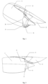
- a fan duct nozzle of an aviation turbofan engine is as shown in Fig. 1 .
- the present disclosure is a novel design of a fan duct nozzle.
- a notch-shaped nozzle is designed on an outer side of an engine pylon 2, a notch 3 and an engine nacelle 1 are integrally designed, and the notch 3 is formed in a location close to the engine pylon 2 and is unilaterally formed in the outer side of the engine pylon 2.
- a depth of the notch 3 is not larger than 20% of a mean aerodynamic chord length of the engine nacelle and not smaller than 5% of the mean aerodynamic chord length of the engine nacelle; and a width of the notch is not larger than 1/4 of a perimeter of the rear edge of the engine nacelle and not smaller than 1/20 of the perimeter of the rear edge of the engine nacelle.
- the depth of the notch 3 is not larger than 10% of the mean aerodynamic chord length of the nacelle, and the width of the notch 3 is not larger than 1/6 of the perimeter of the rear edge of the nacelle.
- a transition between the notch 3 and a rear edge 4 of the engine nacelle has two segments of transition rounded corners, respectively a notch first transition rounded corner 5 and a notch second transition rounded corner 6 in the drawing.
- a role of the transition rounded corners 5 and 6 is stabilizing flowing of a jet flow so as to avoid generation of excessively large separation vortex or aerodynamic noises.
- the transition rounded corners 5 and 6 should be no larger than 90°.
- a percentage of a circular arc section should be no larger than 50% of the width of the notch.
- Main components of the present disclosure and a shape of the nacelle as well as a curved surface of an internal duct of the engine are integrally designed, and the notch nozzle is in a fixed shape, so no motion relation exists.
- the notch nozzle is installed on the outer side of the engine nacelle pylon 2, and a location of the notch 3 is close to the engine nacelle 1 and is on an upper part of the engine nacelle 1; the notch nozzle and the rear edge 4 of the engine nacelle are transited through two segments of transition rounded corners; the notch nozzle 3 and an outer profile of the engine nacelle 1 are integrally designed; and a flow guide curved surface 7 matching the notch 3 in shape is designed on a profile of the fan duct nozzle.
- a design of the flow guide curved surface 7 is as shown in Fig. 3 .
- the flow guide curved surface 7 matches the notch nozzle in shape, is in smooth transition to the profile of the external duct and has one or a plurality of segments of flow guide curved surface controlling lines 8; a 1# chamfer of the flow guide curved surface 7 corresponds to the first transition rounded corner 5 of the notch nozzle in location; and a 2# chamfer of the flow guide curved surface corresponds to the second transition rounded corner 6 of the notch nozzle.
- the flow guide curved surface 7 is shaped by a plurality of bridging curved surfaces, each bridging curved surface maintains curvature continuity with an inner curved surface of the external duct of the engine, and a length of each bridging curved surface is not larger than 50% of a width of the notch 3 so as not to affect a shape of an internal duct nozzle excessively.
- a specific profile and shape need to be determined by an aerodynamic optimization design.
- a role of the flow guide curved surface controlling lines 8 is complementing an airfoil profile of the nacelle so that the airfoil profile of the nacelle with the additional notch design can maintain a streamline shape in low resistance, thus lowering an aerodynamic resistance cost.
- the notch nozzle and the corresponding flow guide curved surface 7 may outwardly extract a part of high-energy flowing of the external duct, charge for local flowing of an upper surface of the airfoil, and thus provide certain flowing protection for a front edge of the airfoil in a high incidence working condition of an airplane. Therefore, negative flowing interference caused by a large-size nacelle on the airfoil may be reduced and a lift coefficient and an aerodynamic efficiency of the airplane may be increased.
- the notch 3 penetrates through the external duct of the nacelle.
- a thickness of the rear edge at the notch 3 will be larger than a thickness of the other part of a rear edge 4 of the nacelle.
- a notch size in the inner profile of the nacelle needs to be larger than a notch size in the outer profile of the nacelle, and then the flow guide curved surface 7 is added to rapidly contract the rear edge 4 of the nacelle at the notch 3, so that the thickness of the rear edge at the notch 3 is roughly equal to the thickness of the other part of the rear edge 4 of the nacelle.
- the present disclosure is innovative in that:
Landscapes
- Engineering & Computer Science (AREA)
- Aviation & Aerospace Engineering (AREA)
- Chemical & Material Sciences (AREA)
- Combustion & Propulsion (AREA)
- Mechanical Engineering (AREA)
- General Engineering & Computer Science (AREA)
- Structures Of Non-Positive Displacement Pumps (AREA)
Applications Claiming Priority (2)
| Application Number | Priority Date | Filing Date | Title |
|---|---|---|---|
| CN202210283285.9A CN114715416B (zh) | 2022-03-22 | 2022-03-22 | 一种航空涡扇发动机及外涵道喷口 |
| PCT/CN2022/129923 WO2023179037A1 (fr) | 2022-03-22 | 2022-11-04 | Turboréacteur à double flux aérien et tuyère de conduit externe |
Publications (2)
| Publication Number | Publication Date |
|---|---|
| EP4331995A1 true EP4331995A1 (fr) | 2024-03-06 |
| EP4331995A4 EP4331995A4 (fr) | 2025-04-23 |
Family
ID=82240504
Family Applications (1)
| Application Number | Title | Priority Date | Filing Date |
|---|---|---|---|
| EP22933088.1A Pending EP4331995A4 (fr) | 2022-03-22 | 2022-11-04 | Turboréacteur à double flux aérien et tuyère de conduit externe |
Country Status (4)
| Country | Link |
|---|---|
| US (1) | US12252250B2 (fr) |
| EP (1) | EP4331995A4 (fr) |
| CN (1) | CN114715416B (fr) |
| WO (1) | WO2023179037A1 (fr) |
Families Citing this family (1)
| Publication number | Priority date | Publication date | Assignee | Title |
|---|---|---|---|---|
| CN114715416B (zh) * | 2022-03-22 | 2025-08-12 | 中国商用飞机有限责任公司北京民用飞机技术研究中心 | 一种航空涡扇发动机及外涵道喷口 |
Family Cites Families (19)
| Publication number | Priority date | Publication date | Assignee | Title |
|---|---|---|---|---|
| US4466587A (en) * | 1981-12-21 | 1984-08-21 | General Electric Company | Nacelle installation |
| US6532729B2 (en) * | 2001-05-31 | 2003-03-18 | General Electric Company | Shelf truncated chevron exhaust nozzle for reduction of exhaust noise and infrared (IR) signature |
| US6969028B2 (en) * | 2003-01-22 | 2005-11-29 | The Boeing Company | Scarf nozzle for a jet engine and method of using the same |
| US6964397B2 (en) * | 2003-07-18 | 2005-11-15 | The Boeing Company | Nacelle chine installation for drag reduction |
| US7543452B2 (en) * | 2005-08-10 | 2009-06-09 | United Technologies Corporation | Serrated nozzle trailing edge for exhaust noise suppression |
| FR2902758B1 (fr) * | 2006-06-21 | 2009-04-10 | Airbus France Sas | Ensemble propulsif d'aeronef comportant un conduit d'ejection avec un bord de fuite echancre |
| US8157207B2 (en) * | 2006-08-09 | 2012-04-17 | The Boeing Company | Jet engine nozzle exit configurations, including projections oriented relative to pylons, and associated systems and methods |
| WO2008151843A1 (fr) * | 2007-06-15 | 2008-12-18 | Airbus Deutschland Gmbh | Fuseau-moteur d'un avion comportant un dispositif de génération de tourbillons |
| CA2648765C (fr) * | 2008-08-11 | 2011-04-19 | The Boeing Company | Configurations de sortie de buse de reacteur comprenant des projections orientees relativement aux pylones et methodes et systemes connexes |
| US8127531B2 (en) * | 2008-11-11 | 2012-03-06 | The Boeing Company | Radially translating fan nozzle nacelle |
| US8875486B2 (en) * | 2010-05-17 | 2014-11-04 | Rohr, Inc. | Guide system for nacelle assembly |
| FR2993921B1 (fr) * | 2012-07-26 | 2014-07-18 | Snecma | Procede pour ameliorer les performances du systeme d'ejection d'un turbomoteur d'aeronef a double flux separes, systeme d'ejection et turbomoteur correspondants. |
| US10240561B2 (en) * | 2013-03-15 | 2019-03-26 | United Technologies Corporation | Aerodynamic track fairing for a gas turbine engine fan nacelle |
| US10570926B2 (en) * | 2015-12-03 | 2020-02-25 | The Boeing Company | Variable-geometry ducted fan |
| US11053888B2 (en) * | 2017-11-01 | 2021-07-06 | The Boeing Company | Fan cowl with a serrated trailing edge providing attached flow in reverse thrust mode |
| US11613345B2 (en) * | 2019-05-20 | 2023-03-28 | The Boeing Company | Aircraft nacelles having adjustable chines |
| CN112824665B (zh) * | 2019-11-21 | 2022-02-18 | 中国航发商用航空发动机有限责任公司 | 外涵喷管驱动装置、组件以及气流输出面积调整方法 |
| CN217416120U (zh) * | 2022-03-22 | 2022-09-13 | 中国商用飞机有限责任公司北京民用飞机技术研究中心 | 一种航空涡扇发动机及外涵道喷口 |
| CN114715416B (zh) * | 2022-03-22 | 2025-08-12 | 中国商用飞机有限责任公司北京民用飞机技术研究中心 | 一种航空涡扇发动机及外涵道喷口 |
-
2022
- 2022-03-22 CN CN202210283285.9A patent/CN114715416B/zh active Active
- 2022-11-04 EP EP22933088.1A patent/EP4331995A4/fr active Pending
- 2022-11-04 WO PCT/CN2022/129923 patent/WO2023179037A1/fr not_active Ceased
-
2023
- 2023-12-26 US US18/396,195 patent/US12252250B2/en active Active
Also Published As
| Publication number | Publication date |
|---|---|
| US20240124121A1 (en) | 2024-04-18 |
| CN114715416B (zh) | 2025-08-12 |
| US12252250B2 (en) | 2025-03-18 |
| EP4331995A4 (fr) | 2025-04-23 |
| WO2023179037A1 (fr) | 2023-09-28 |
| CN114715416A (zh) | 2022-07-08 |
Similar Documents
| Publication | Publication Date | Title |
|---|---|---|
| US4598885A (en) | Airplane airframe | |
| US10625847B2 (en) | Split winglet | |
| CN108639339B (zh) | 一种无人机气动布局 | |
| US11738857B2 (en) | Wing tip device | |
| EP0735970B1 (fr) | Ensemble aile/nacelle d'avion | |
| CN107140180B (zh) | 高超声速乘波双翼气动布局 | |
| US4629147A (en) | Over-the-wing propeller | |
| US12252250B2 (en) | Aviation turbofan engine and fan duct nozzle | |
| CN109677587B (zh) | 一种可兼顾高低速飞行的斜置翼飞机的控制方法 | |
| CN117163280B (zh) | 一种无尾翼身融合布局飞机的可收放边条翼 | |
| CN111498084A (zh) | 一种应用于高空高速长航时无人机的低阻层流翼型 | |
| CN113619772B (zh) | 一种协同射流式二级喷口环量控制翼型 | |
| CN217416120U (zh) | 一种航空涡扇发动机及外涵道喷口 | |
| CN115180118A (zh) | 一种具有联合射流控制的高升力机翼 | |
| CN214524368U (zh) | 一种带有近距耦合导流片的下单翼飞机 | |
| CN219192541U (zh) | 一种仿生鹰翼翼梢小翼气动结构 | |
| CN216509107U (zh) | 带进气畸变控制结构的飞机发动机短舱 | |
| CN217416091U (zh) | 一种用于飞行器的机翼及配备有该机翼的飞行器 | |
| CN105775108B (zh) | 一种外载式布局高空螺旋桨 | |
| CN205418070U (zh) | 一种类三角布局高空螺旋桨 | |
| CN112849387A (zh) | 一种考虑动力安装平台的飞翼反弯翼型 | |
| CN205418071U (zh) | 一种外载式布局高空螺旋桨 | |
| CN115973408B (zh) | 一种跨速域变体飞行器 | |
| CN105691596B (zh) | 一种类三角布局高空螺旋桨 | |
| CN223396359U (zh) | 一种串列翼与水滴型机身组合的气动布局结构 |
Legal Events
| Date | Code | Title | Description |
|---|---|---|---|
| STAA | Information on the status of an ep patent application or granted ep patent |
Free format text: STATUS: THE INTERNATIONAL PUBLICATION HAS BEEN MADE |
|
| PUAI | Public reference made under article 153(3) epc to a published international application that has entered the european phase |
Free format text: ORIGINAL CODE: 0009012 |
|
| STAA | Information on the status of an ep patent application or granted ep patent |
Free format text: STATUS: REQUEST FOR EXAMINATION WAS MADE |
|
| 17P | Request for examination filed |
Effective date: 20231201 |
|
| AK | Designated contracting states |
Kind code of ref document: A1 Designated state(s): AL AT BE BG CH CY CZ DE DK EE ES FI FR GB GR HR HU IE IS IT LI LT LU LV MC ME MK MT NL NO PL PT RO RS SE SI SK SM TR |
|
| A4 | Supplementary search report drawn up and despatched |
Effective date: 20250325 |
|
| RIC1 | Information provided on ipc code assigned before grant |
Ipc: F02K 1/52 20060101ALI20250319BHEP Ipc: B64D 29/00 20060101AFI20250319BHEP |
|
| DAV | Request for validation of the european patent (deleted) | ||
| DAX | Request for extension of the european patent (deleted) |