EP4332285A1 - Dispositif de guidage pour un métier à filer à anneaux, métier à filer à anneaux ainsi qu'utilisation d'un dispositif de guidage - Google Patents
Dispositif de guidage pour un métier à filer à anneaux, métier à filer à anneaux ainsi qu'utilisation d'un dispositif de guidage Download PDFInfo
- Publication number
- EP4332285A1 EP4332285A1 EP23193341.7A EP23193341A EP4332285A1 EP 4332285 A1 EP4332285 A1 EP 4332285A1 EP 23193341 A EP23193341 A EP 23193341A EP 4332285 A1 EP4332285 A1 EP 4332285A1
- Authority
- EP
- European Patent Office
- Prior art keywords
- guide
- guide element
- fiber structure
- guide device
- spinning machine
- Prior art date
- Legal status (The legal status is an assumption and is not a legal conclusion. Google has not performed a legal analysis and makes no representation as to the accuracy of the status listed.)
- Pending
Links
Images

Classifications
-
- D—TEXTILES; PAPER
- D01—NATURAL OR MAN-MADE THREADS OR FIBRES; SPINNING
- D01H—SPINNING OR TWISTING
- D01H13/00—Other common constructional features, details or accessories
- D01H13/04—Guides for slivers, rovings, or yarns; Smoothing dies
-
- B—PERFORMING OPERATIONS; TRANSPORTING
- B65—CONVEYING; PACKING; STORING; HANDLING THIN OR FILAMENTARY MATERIAL
- B65H—HANDLING THIN OR FILAMENTARY MATERIAL, e.g. SHEETS, WEBS, CABLES
- B65H57/00—Guides for filamentary materials; Supports therefor
- B65H57/003—Arrangements for threading or unthreading the guide
-
- B—PERFORMING OPERATIONS; TRANSPORTING
- B65—CONVEYING; PACKING; STORING; HANDLING THIN OR FILAMENTARY MATERIAL
- B65H—HANDLING THIN OR FILAMENTARY MATERIAL, e.g. SHEETS, WEBS, CABLES
- B65H57/00—Guides for filamentary materials; Supports therefor
- B65H57/06—Annular guiding surfaces; Eyes, e.g. pigtails
-
- D—TEXTILES; PAPER
- D01—NATURAL OR MAN-MADE THREADS OR FIBRES; SPINNING
- D01H—SPINNING OR TWISTING
- D01H1/00—Spinning or twisting machines in which the product is wound-up continuously
- D01H1/02—Spinning or twisting machines in which the product is wound-up continuously ring type
-
- D—TEXTILES; PAPER
- D01—NATURAL OR MAN-MADE THREADS OR FIBRES; SPINNING
- D01H—SPINNING OR TWISTING
- D01H1/00—Spinning or twisting machines in which the product is wound-up continuously
- D01H1/14—Details
- D01H1/42—Guards or protectors for yarns or threads, e.g. separator plates, anti-ballooning devices
- D01H1/425—Anti-ballooning rings
-
- B—PERFORMING OPERATIONS; TRANSPORTING
- B65—CONVEYING; PACKING; STORING; HANDLING THIN OR FILAMENTARY MATERIAL
- B65H—HANDLING THIN OR FILAMENTARY MATERIAL, e.g. SHEETS, WEBS, CABLES
- B65H2701/00—Handled material; Storage means
- B65H2701/30—Handled filamentary material
- B65H2701/31—Textiles threads or artificial strands of filaments
Definitions
- the present invention relates to a guide device for a ring spinning machine for guiding a strand-shaped fiber structure with a guide area which limits freedom of movement of the fiber structure perpendicular to a running direction of the fiber structure and with an opening for introducing the fiber structure into the guide area.
- the invention also relates to a ring spinning machine with at least one workstation for producing a yarn, the workstation having a drafting system for stretching a fiber structure, a ring traveler rotating on a spinning ring and a guide device for guiding the fiber structure.
- the invention relates to the use of a guide device in a ring spinning machine.
- Ring spinning machines for producing a yarn from a fiber structure have been known for a long time.
- ring spinning machines have a drafting system for stretching the fiber structure. After the drafting system, the stretched fiber structure is wound onto a spinning tube via a ring runner rotating on a spinning ring. This gives the fiber structure a twist and turns it into a yarn.
- the ring spinning machine usually has at least one guide device, through which at least one movement of the fiber structure is limited perpendicular to its direction of travel. On the one hand, the guide device can prevent unwanted movements of the fiber structure.
- the tension of the fiber structure can also be specifically controlled by the guide device.
- Known guide devices generally have an opening for threading the fiber structure on, via which the fiber structure can be brought into a guide area of the guide device, for example before spinning again.
- Such known guide devices are, for example, spirally bent wires, such as those in DE 35 20 864 A1 or the US 4,114,829 A are revealed.
- a disadvantage of the known guide devices is that it is difficult to thread the fiber structure, especially using a service robot, as has recently been used more and more frequently in ring spinning machines.
- cleaning the known guide devices also involves increased effort, since fibers that come loose from the fiber structure easily get stuck on the turns of the wire.
- the object of the present invention is to eliminate the disadvantages known from the prior art, in particular to create a guide device for a ring spinning machine which overcomes the disadvantages mentioned.
- the task is solved by a guide device, a ring spinning machine and the use of a guide device with the features of the independent claims.
- the guide device for a ring spinning machine for guiding a strand-shaped fiber structure with a guide area that limits freedom of movement of the fiber structure perpendicular to a running direction of the fiber structure and with an opening for introducing the fiber structure into the guide area.
- the guide device has a first guide element with a first guide section and a second guide element with a second guide section.
- the first leadership section and the second guide section together form the guide area in the form of a closed contour in a top view of the guide device.
- the proposed guide device can be cleaned more easily compared to the known guide devices.
- the first guide element and the second guide element can be easily spaced apart in such a way that fewer fibers get stuck on the guide device.
- the closed contour also prevents the fiber structure from jumping out of the guide area of the guide device or making other unwanted movements.
- the guide device limits the freedom of movement of the fiber structure, particularly perpendicular to its direction of travel in a ring spinning machine. It is also conceivable that freedom of movement of the fiber structure in other directions is restricted by the guide device.
- the closed contour of the guide area has the shape of a circle, an ellipse or a drop.
- the contour of the guide area can be adapted in particular to the shape of the movement of the fiber structure, which it carries out through the guidance of the ring traveler. In this way, unnecessary friction of the fiber structure on the guide device and thus the detachment of additional fibers can be avoided.
- the tension of the fiber structure can also be influenced by the shape of the contour of the guide area.
- first guide element and the second guide element are arranged essentially parallel to one another. This contributes to further simplifying the threading of the fiber structure into the guide area of the guide device.
- the first guide element and the second guide element can, for example, be plate-shaped.
- the first guide element and the second guide element can in particular each be arranged in a plane, the planes being essentially parallel to one another.
- the first guide element and the second guide element are arranged parallel to one another. It is conceivable that the first guide element and/or the second guide element comprise a plurality of flat sections, which in turn run parallel to one another.
- first guide element and the second guide element are arranged one above the other when the guide device is used as intended.
- the closed contour of the guide area can be constructively implemented in an efficient manner.
- the first guide element and the second guide element are arranged one above the other in two parallel planes.
- first guide element and the second guide element are connected to one another via a connecting section, the connecting section running perpendicular to the first guide element and the second guide element.
- the connecting section increases the stability of the guide device. It is conceivable that during production the first guide element and the second guide element are initially produced as a common component, for example as a stamped part. The second guide element can then, for example, in a further manufacturing step from the plane of the first guide element be bent out and then aligned essentially parallel to the first guide element. The connecting section then results from the curved section between the first guide element and the second guide element. If the first guide element and the second guide element are provided as separate components, the connecting section can be formed, for example, by one or more connecting elements, such as screws, bolts or clamps.
- the opening is at least partially formed by a distance between the first guide element and the second guide element. This contributes to further simplifying the threading process of the fiber structure into the guide area of the guide device.
- the fiber structure In order to thread the fiber structure into the guide device, the fiber structure must be temporarily aligned along the opening, i.e. along the distance between the first guide element and the second guide element. If the first guide element and the second guide element are aligned parallel to one another, as described above, the fiber structure for threading must also be aligned essentially parallel to the two guide elements, for example.
- the size of the distance between the first guide element and the second guide element can be selected such that automatic threading of the fiber structure into the guide area of the guide device is possible without any problems.
- the first guide element has an entry area connected to the first guide section.
- the fiber structure can be guided via the entry area when threading into the first guide section.
- the entry area can, for example, be designed in the form of a channel with parallel side walls. He leads in particular from an outer edge of the first guide element to the first guide section, which is arranged, for example, essentially centrally between two outer edges of the first guide element. Depending on how the side walls of the entry area are spaced, the freedom of movement of the fiber structure when threading can be limited.
- the entry area is at least partially formed by an arm which extends beyond the second guide element in the top view of the guide device.
- the arm can be used, for example, to catch and fix the fiber structure when threading.
- An outer edge of the arm can, for example, merge directly into one of the side walls of the entry area already described. This further simplifies the threading of the fiber structure first into the first guide section and then into the second guide section of the second guide element, in particular by a robot.
- An exemplary threading process of the fiber structure into the guide area of the guide device can look like this.
- the fiber bandage is brought into the area of the arm and captured by it.
- the fiber structure is then moved in the direction of the first guide section.
- the fiber structure moves along the arm and the entry area into the first guide section.
- the fiber structure is at least partially aligned along the opening between the first and second guide elements.
- the fiber structure can be brought into the second guide section of the second guide element, which completes the process.
- first guide element and/or the second guide element are at least partially made as a stamped part, preferably Metal, is formed.
- Metal is a robust and durable material.
- the first and/or the second guide element can be smoothed after punching, for example by vibratory grinding. In particular, this rounds off the edges of the components so that damage to the fiber structure is less likely.
- the first guide element and/or the second guide element can also be provided with one or more bends, particularly in the area of the edges. This can increase the stability of the components.
- Various hardening processes for the stamped parts are also conceivable.
- the first guide element and the second guide element can be produced, for example, as individual stamped parts. These are then assembled to form the guide device. As already mentioned, the first guide element and the second guide element can in particular also be produced as a single stamped part. The second guide element is then bent out of the plane of the first guide element, for example in a further method step, and preferably aligned essentially parallel to the first guide element.
- the first guide element and/or the second guide element has a recess, the recess serving to fasten the guide device to a support of a workstation of a ring spinning machine.
- the recess can be closed to the outside or open.
- the recess serves to accommodate or pass through a screw, with the help of which the guide element is connected to the carrier can be connected.
- the recess is not connected to the first guide section and the second guide section.
- the ring spinning machine comprises at least one workstation for producing a yarn.
- the workstation has a drafting system for stretching a fiber structure, a ring traveler rotating on a spinning ring and a guide device for guiding the fiber structure.
- the guide device is designed according to the previous description.
- the features mentioned can be implemented individually or in any combination.
- the advantages described also result from the provision of the guide device according to the invention for the ring spinning machine. In particular, threading the fiber structure into the guide device and cleaning the guide device on the ring spinning machine are simplified.
- the guide device is arranged between the drafting system and the spinning ring.
- guidance of the fiber structure is particularly important in order to avoid damage to the fiber structure on the one hand and to control the tension of the fiber structure on the other hand.
- the advantages of the guide device according to the invention therefore unfold in a special way in this area. It is conceivable that one or more balloon constriction rings are also arranged between the drafting system and the spinning ring in order to limit the expansion of the balloons of the fiber structure that may arise as a result of the rotation of the spinning ring.
- the use of a guide device according to the previous description in a ring spinning machine is also proposed, wherein the ring spinning machine is designed in particular as described above.
- the ring spinning machine is designed in particular as described above.
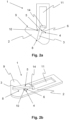
- Figure 1a shows a top view of a first exemplary embodiment of a guide device 1 according to the invention.
- the guide device 1 comprises a first guide element 2 and a second guide element 3, which are arranged one above the other.
- the first guide element 2 has a first guide section 4.
- the second guide element 3 has a second guide section 5.
- the first guide section 4 and the second guide section 5 together form a guide area 6 in which a strand-shaped fiber structure 7 (see Figure 4 ) is guided when the guide device 1 is used as intended.
- the first guide section 4 and the second guide section 5 form the guide area 6 in the form of a closed contour.
- the closed contour of the guide area 6 has the shape of a circle.
- the contour of the guide area 6 can also have the shape of an ellipse or a drop, for example.
- first guide element 2 and the second guide element 3 are arranged spaced apart from one another at least in a front region.
- a distance between the first guide element 2 and the second guide element 3 forms an opening 8, which is suitable for easily threading the fiber structure 7 into the guide area 6.
- the first guide element 2 and the second guide element 3 are arranged essentially parallel to one another.
- the first guide element 2 forms a first level and the second guide element 3 forms a second level, the levels being parallel to one another.
- the first guide element 2 and the second guide element 3 are plate-shaped.
- the first guide element 2 and the second guide element 3 are designed as metallic stamped parts.
- the first guide element 2 has an arm 9.
- the arm 9 merges into an entry area 10.
- the fiber structure 7 is initially captured by the arm 9, for example.
- the fiber structure 7 is then brought into the first guide section 4 via the entry area 10.
- the fiber structure 7 is simultaneously or subsequently brought into the second guide section 5 of the second guide element 3.
- the arm 9 extends in the top view Figure 1a beyond the second guide element 3.
- the arm 9 can fulfill the function of catching the fiber structure 7 without the fiber structure 7 getting caught in other areas of the guide device 1.
- the first guide element 2 and the second guide element 3 each have a recess 11, which is used to fasten the guide device 1 to a carrier 12 of a workstation 13 (see Figure 4 ) is used for a ring spinning machine.
- the recesses 11 lie one above the other, so that essentially a continuous recess 11 results.
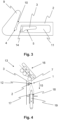
- the Figures 2a and 2b show a further exemplary embodiment of the guide device 1 according to the invention, wherein the Figure 2a another one Top view of the guide device 1 and the Figure 2a a perspective view of the guide device 1.
- the first guide element 2 and the second guide element 3 are initially designed as a common component. This is also shown in more detail in Figure 3.
- the essential features of the guide device 1 from this exemplary embodiment correspond to those of the first exemplary embodiment from the Figures 1a and 1b .
- the arrangement of the first guide section 4 of the first guide element 2 and the second guide section 5 of the second guide element 3 results in a guide area 6 with a closed contour.
- a significant difference from the first exemplary embodiment is that the first guide element 2 and the second guide element 3 are connected to one another via a connecting section 14.
- the connecting section 14 runs essentially perpendicular to the first guide element 2 and to the second guide element 3.
- the threading process of the fiber structure 7 described in the first exemplary embodiment runs the same way in this exemplary embodiment of the guide device 1.
- the first guide element 2 has the recess 11, which is used for fastening the guide device 1 on the carrier 12 of the workstation 13 of the ring spinning machine is used.
- the Figure 3 indicates an intermediate step in a manufacturing process of the guide device 1 according to the second exemplary embodiment.
- the first guide element 2 and the second guide element 3 are, for example, initially manufactured as a common stamped part.
- the second guide element 3 is initially provided in the recess 11.
- the second guide element 3 is bent upwards and aligned essentially parallel to the first guide element 2.
- the end result of the manufacturing process is the guide device 1 according to the exemplary embodiment Figures 2a and 2b .
- Figure 4 shows the workstation 13 of the ring spinning machine, not shown, with the guide device 1 according to the invention.
- the guide device 1 is suitable for guiding the strand-shaped fiber structure 7, in particular for restricting freedom of movement of the fiber structure 7 perpendicular to a running direction 15 of the fiber structure 7 .
- the first guide element 2 and the second guide element 3 are arranged one above the other in the workstation 13.
- the guide device 1 is arranged between a drafting system 16 and a spinning ring 17.
- the fiber structure 7 is first stretched in the drafting system 16 and then wound onto a spinning tube 19 via a ring traveler 18 rotating on the spinning ring 17. This gives the fiber structure 7 a twist.
- the guide device 1 is fastened via the recess 11 in the carrier 12 of the workstation 13.
Landscapes
- Engineering & Computer Science (AREA)
- Mechanical Engineering (AREA)
- Textile Engineering (AREA)
- Spinning Or Twisting Of Yarns (AREA)
Applications Claiming Priority (1)
| Application Number | Priority Date | Filing Date | Title |
|---|---|---|---|
| CH001024/2022A CH720005A1 (de) | 2022-09-02 | 2022-09-02 | Führungsvorrichtung für eine Ringspinnmaschine, Ringspinnmaschine sowie Verwendung einer Führungsvorrichtung. |
Publications (1)
| Publication Number | Publication Date |
|---|---|
| EP4332285A1 true EP4332285A1 (fr) | 2024-03-06 |
Family
ID=87845481
Family Applications (1)
| Application Number | Title | Priority Date | Filing Date |
|---|---|---|---|
| EP23193341.7A Pending EP4332285A1 (fr) | 2022-09-02 | 2023-08-25 | Dispositif de guidage pour un métier à filer à anneaux, métier à filer à anneaux ainsi qu'utilisation d'un dispositif de guidage |
Country Status (3)
| Country | Link |
|---|---|
| EP (1) | EP4332285A1 (fr) |
| CN (1) | CN117646296A (fr) |
| CH (1) | CH720005A1 (fr) |
Cited By (1)
| Publication number | Priority date | Publication date | Assignee | Title |
|---|---|---|---|---|
| WO2025233119A1 (fr) | 2024-05-08 | 2025-11-13 | Rieter Ag | Appareil de manipulation pour un dispositif d'entretien servant à nettoyer des éléments de guidage de fil, et procédé de nettoyage |
Citations (6)
| Publication number | Priority date | Publication date | Assignee | Title |
|---|---|---|---|---|
| GB191117473A (en) * | 1911-08-01 | 1912-03-21 | Grindrod Kershaw | Improvements in Thread guides, for use in Spinning Machines, Doubling Machines, Winding Machines, Reels, Warping Machines, Beaming Machines and other Machines in which Yarns or Threads or Groups or Assemblages thereof are Wound or Unwound. |
| US2202937A (en) * | 1938-07-28 | 1940-06-04 | Celanese Corp | Thread guide |
| US4114829A (en) | 1977-06-21 | 1978-09-19 | The Partnership Of W. L. Boehler And A. G. Whaley Co., Inc. | Guide for filamentary material |
| DE3520864A1 (de) | 1985-06-11 | 1986-12-11 | Hacoba Textilmaschinen Gmbh & Co Kg, 5600 Wuppertal | Drahtfoermiger fadenfuehrer, insbesondere fuer fadenballonabzug |
| EP0534060A1 (fr) * | 1991-09-24 | 1993-03-31 | Bettini S.P.A. | Procédé pour la fabrication d'anneaux de guidage de fil |
| CN206359692U (zh) * | 2016-12-28 | 2017-07-28 | 陕西纺织器材研究所 | 一种细纱机组合式微孔导纱钩 |
Family Cites Families (1)
| Publication number | Priority date | Publication date | Assignee | Title |
|---|---|---|---|---|
| CH454696A (de) * | 1967-09-07 | 1968-08-15 | Heberlein & Co Ag | Doppelfadenführer |
-
2022
- 2022-09-02 CH CH001024/2022A patent/CH720005A1/de not_active Application Discontinuation
-
2023
- 2023-08-25 EP EP23193341.7A patent/EP4332285A1/fr active Pending
- 2023-09-01 CN CN202311127759.1A patent/CN117646296A/zh active Pending
Patent Citations (6)
| Publication number | Priority date | Publication date | Assignee | Title |
|---|---|---|---|---|
| GB191117473A (en) * | 1911-08-01 | 1912-03-21 | Grindrod Kershaw | Improvements in Thread guides, for use in Spinning Machines, Doubling Machines, Winding Machines, Reels, Warping Machines, Beaming Machines and other Machines in which Yarns or Threads or Groups or Assemblages thereof are Wound or Unwound. |
| US2202937A (en) * | 1938-07-28 | 1940-06-04 | Celanese Corp | Thread guide |
| US4114829A (en) | 1977-06-21 | 1978-09-19 | The Partnership Of W. L. Boehler And A. G. Whaley Co., Inc. | Guide for filamentary material |
| DE3520864A1 (de) | 1985-06-11 | 1986-12-11 | Hacoba Textilmaschinen Gmbh & Co Kg, 5600 Wuppertal | Drahtfoermiger fadenfuehrer, insbesondere fuer fadenballonabzug |
| EP0534060A1 (fr) * | 1991-09-24 | 1993-03-31 | Bettini S.P.A. | Procédé pour la fabrication d'anneaux de guidage de fil |
| CN206359692U (zh) * | 2016-12-28 | 2017-07-28 | 陕西纺织器材研究所 | 一种细纱机组合式微孔导纱钩 |
Cited By (1)
| Publication number | Priority date | Publication date | Assignee | Title |
|---|---|---|---|---|
| WO2025233119A1 (fr) | 2024-05-08 | 2025-11-13 | Rieter Ag | Appareil de manipulation pour un dispositif d'entretien servant à nettoyer des éléments de guidage de fil, et procédé de nettoyage |
Also Published As
| Publication number | Publication date |
|---|---|
| CN117646296A (zh) | 2024-03-05 |
| CH720005A1 (de) | 2024-03-15 |
Similar Documents
| Publication | Publication Date | Title |
|---|---|---|
| DE3413945C2 (de) | Mit schraubenlinienförmigen Nuten versehene Zahnhaltevorrichtung | |
| DE3304784A1 (de) | Vorrichtung zur umwandlung einer drehbewegung in eine linearbewegung | |
| DE69202679T2 (de) | Biege-Schermaschine mit mehreren Arbeitsebenen. | |
| EP0566163B1 (fr) | Lisse | |
| EP0318802B1 (fr) | Système d'insertion de la trame pour machines à tisser pneumatiques avec au moins deux tuyères réunies en faisceau | |
| DE102009022191B3 (de) | Fadenführeranordnung einer Kettenwirkmaschine | |
| EP4332285A1 (fr) | Dispositif de guidage pour un métier à filer à anneaux, métier à filer à anneaux ainsi qu'utilisation d'un dispositif de guidage | |
| EP2454403B1 (fr) | Machine à filer à jet d'air | |
| WO2022049191A1 (fr) | Poste de filage d'un continu à filer à anneaux, continu à filer à anneaux et procédé pour faire fonctionner un poste de filage d'un continu à filer à anneaux | |
| CH718214A1 (de) | Führungselement sowie damit ausgestattete Arbeitsstelle einer Ringspinnmaschine. | |
| DE2452758A1 (de) | Vorrichtung zur bearbeitung von werkstuecken | |
| EP1657328B1 (fr) | Dispositif d'ouvraison comprennant des dents avec contour amélioré | |
| DE3828319C2 (fr) | ||
| CH642406A5 (de) | Verbindung von faserverbaenden, verfahren zur erzeugung der verbindung und vorrichtung zur ausfuehrung des verfahrens. | |
| DE2832763A1 (de) | Stuetzspirale fuer einen schlauch und schlauchanordnung mit stuetzspirale | |
| DE2242755C3 (de) | Ballon begrenzerring | |
| EP3257979B1 (fr) | Dispositif pince-fil | |
| EP2123812B1 (fr) | Métier à filer ou retordeuse | |
| EP0620872A1 (fr) | Procede et dispositif a texturer des fils thermoplastiques. | |
| EP0592866B1 (fr) | Tube de sortie de fil avec un support | |
| EP2019157B1 (fr) | Lisse coudée et étroite | |
| DE19653359B4 (de) | Auflösewalze für eine Offenend-Spinnvorrichtung | |
| DE69615084T2 (de) | Verfahren zur Herstellung eines Fütterungsgitterhebels, ein dadurch hergestellter Hebel und ein Futterungsgitter mit einem solchen Hebel | |
| DE19906201B4 (de) | Vorrichtung zur Befestigung eines Fadens an einer chirurgischen Nadel | |
| DE2713624A1 (de) | Verfahren und vorrichtung zum selbsttaetigen einfaedeln eines fadens in einen spinn- oder zwirnlaeufer |
Legal Events
| Date | Code | Title | Description |
|---|---|---|---|
| PUAI | Public reference made under article 153(3) epc to a published international application that has entered the european phase |
Free format text: ORIGINAL CODE: 0009012 |
|
| STAA | Information on the status of an ep patent application or granted ep patent |
Free format text: STATUS: THE APPLICATION HAS BEEN PUBLISHED |
|
| AK | Designated contracting states |
Kind code of ref document: A1 Designated state(s): AL AT BE BG CH CY CZ DE DK EE ES FI FR GB GR HR HU IE IS IT LI LT LU LV MC ME MK MT NL NO PL PT RO RS SE SI SK SM TR |
|
| RAP3 | Party data changed (applicant data changed or rights of an application transferred) |
Owner name: RIETER AG |
|
| STAA | Information on the status of an ep patent application or granted ep patent |
Free format text: STATUS: REQUEST FOR EXAMINATION WAS MADE |
|
| 17P | Request for examination filed |
Effective date: 20240819 |
|
| RBV | Designated contracting states (corrected) |
Designated state(s): AL AT BE BG CH CY CZ DE DK EE ES FI FR GB GR HR HU IE IS IT LI LT LU LV MC ME MK MT NL NO PL PT RO RS SE SI SK SM TR |
|
| STAA | Information on the status of an ep patent application or granted ep patent |
Free format text: STATUS: EXAMINATION IS IN PROGRESS |
|
| 17Q | First examination report despatched |
Effective date: 20251104 |