EP4332304A1 - Machine automotrice de traitement du sol avec moteurs jumelés et transmission de puissance différente de la machine - Google Patents
Machine automotrice de traitement du sol avec moteurs jumelés et transmission de puissance différente de la machine Download PDFInfo
- Publication number
- EP4332304A1 EP4332304A1 EP23194878.7A EP23194878A EP4332304A1 EP 4332304 A1 EP4332304 A1 EP 4332304A1 EP 23194878 A EP23194878 A EP 23194878A EP 4332304 A1 EP4332304 A1 EP 4332304A1
- Authority
- EP
- European Patent Office
- Prior art keywords
- motor
- working
- torque
- gear
- speed
- Prior art date
- Legal status (The legal status is an assumption and is not a legal conclusion. Google has not performed a legal analysis and makes no representation as to the accuracy of the status listed.)
- Granted
Links
Images


Classifications
-
- B—PERFORMING OPERATIONS; TRANSPORTING
- B60—VEHICLES IN GENERAL
- B60K—ARRANGEMENT OR MOUNTING OF PROPULSION UNITS OR OF TRANSMISSIONS IN VEHICLES; ARRANGEMENT OR MOUNTING OF PLURAL DIVERSE PRIME-MOVERS IN VEHICLES; AUXILIARY DRIVES FOR VEHICLES; INSTRUMENTATION OR DASHBOARDS FOR VEHICLES; ARRANGEMENTS IN CONNECTION WITH COOLING, AIR INTAKE, GAS EXHAUST OR FUEL SUPPLY OF PROPULSION UNITS IN VEHICLES
- B60K17/00—Arrangement or mounting of transmissions in vehicles
- B60K17/02—Arrangement or mounting of transmissions in vehicles characterised by arrangement, location, or kind of clutch
-
- B—PERFORMING OPERATIONS; TRANSPORTING
- B60—VEHICLES IN GENERAL
- B60K—ARRANGEMENT OR MOUNTING OF PROPULSION UNITS OR OF TRANSMISSIONS IN VEHICLES; ARRANGEMENT OR MOUNTING OF PLURAL DIVERSE PRIME-MOVERS IN VEHICLES; AUXILIARY DRIVES FOR VEHICLES; INSTRUMENTATION OR DASHBOARDS FOR VEHICLES; ARRANGEMENTS IN CONNECTION WITH COOLING, AIR INTAKE, GAS EXHAUST OR FUEL SUPPLY OF PROPULSION UNITS IN VEHICLES
- B60K1/00—Arrangement or mounting of electrical propulsion units
- B60K1/02—Arrangement or mounting of electrical propulsion units comprising more than one electric motor
-
- B—PERFORMING OPERATIONS; TRANSPORTING
- B60—VEHICLES IN GENERAL
- B60K—ARRANGEMENT OR MOUNTING OF PROPULSION UNITS OR OF TRANSMISSIONS IN VEHICLES; ARRANGEMENT OR MOUNTING OF PLURAL DIVERSE PRIME-MOVERS IN VEHICLES; AUXILIARY DRIVES FOR VEHICLES; INSTRUMENTATION OR DASHBOARDS FOR VEHICLES; ARRANGEMENTS IN CONNECTION WITH COOLING, AIR INTAKE, GAS EXHAUST OR FUEL SUPPLY OF PROPULSION UNITS IN VEHICLES
- B60K17/00—Arrangement or mounting of transmissions in vehicles
- B60K17/04—Arrangement or mounting of transmissions in vehicles characterised by arrangement, location or kind of gearing
- B60K17/043—Transmission unit disposed in on near the vehicle wheel, or between the differential gear unit and the wheel
- B60K17/046—Transmission unit disposed in on near the vehicle wheel, or between the differential gear unit and the wheel with planetary gearing having orbital motion
-
- B—PERFORMING OPERATIONS; TRANSPORTING
- B60—VEHICLES IN GENERAL
- B60K—ARRANGEMENT OR MOUNTING OF PROPULSION UNITS OR OF TRANSMISSIONS IN VEHICLES; ARRANGEMENT OR MOUNTING OF PLURAL DIVERSE PRIME-MOVERS IN VEHICLES; AUXILIARY DRIVES FOR VEHICLES; INSTRUMENTATION OR DASHBOARDS FOR VEHICLES; ARRANGEMENTS IN CONNECTION WITH COOLING, AIR INTAKE, GAS EXHAUST OR FUEL SUPPLY OF PROPULSION UNITS IN VEHICLES
- B60K17/00—Arrangement or mounting of transmissions in vehicles
- B60K17/28—Arrangement or mounting of transmissions in vehicles characterised by arrangement, location, or type of power take-off
-
- B—PERFORMING OPERATIONS; TRANSPORTING
- B60—VEHICLES IN GENERAL
- B60K—ARRANGEMENT OR MOUNTING OF PROPULSION UNITS OR OF TRANSMISSIONS IN VEHICLES; ARRANGEMENT OR MOUNTING OF PLURAL DIVERSE PRIME-MOVERS IN VEHICLES; AUXILIARY DRIVES FOR VEHICLES; INSTRUMENTATION OR DASHBOARDS FOR VEHICLES; ARRANGEMENTS IN CONNECTION WITH COOLING, AIR INTAKE, GAS EXHAUST OR FUEL SUPPLY OF PROPULSION UNITS IN VEHICLES
- B60K25/00—Auxiliary drives
-
- B—PERFORMING OPERATIONS; TRANSPORTING
- B60—VEHICLES IN GENERAL
- B60K—ARRANGEMENT OR MOUNTING OF PROPULSION UNITS OR OF TRANSMISSIONS IN VEHICLES; ARRANGEMENT OR MOUNTING OF PLURAL DIVERSE PRIME-MOVERS IN VEHICLES; AUXILIARY DRIVES FOR VEHICLES; INSTRUMENTATION OR DASHBOARDS FOR VEHICLES; ARRANGEMENTS IN CONNECTION WITH COOLING, AIR INTAKE, GAS EXHAUST OR FUEL SUPPLY OF PROPULSION UNITS IN VEHICLES
- B60K5/00—Arrangement or mounting of internal-combustion or jet-propulsion units
- B60K5/12—Arrangement of engine supports
-
- E—FIXED CONSTRUCTIONS
- E01—CONSTRUCTION OF ROADS, RAILWAYS, OR BRIDGES
- E01C—CONSTRUCTION OF, OR SURFACES FOR, ROADS, SPORTS GROUNDS, OR THE LIKE; MACHINES OR AUXILIARY TOOLS FOR CONSTRUCTION OR REPAIR
- E01C23/00—Auxiliary devices or arrangements for constructing, repairing, reconditioning, or taking-up road or like surfaces
- E01C23/06—Devices or arrangements for working the finished surface; Devices for repairing or reconditioning the surface of damaged paving; Recycling in place or on the road
- E01C23/065—Recycling in place or on the road, i.e. hot or cold reprocessing of paving in situ or on the traffic surface, with or without adding virgin material or lifting of salvaged material; Repairs or resurfacing involving at least partial reprocessing of the existing paving
-
- E—FIXED CONSTRUCTIONS
- E01—CONSTRUCTION OF ROADS, RAILWAYS, OR BRIDGES
- E01C—CONSTRUCTION OF, OR SURFACES FOR, ROADS, SPORTS GROUNDS, OR THE LIKE; MACHINES OR AUXILIARY TOOLS FOR CONSTRUCTION OR REPAIR
- E01C23/00—Auxiliary devices or arrangements for constructing, repairing, reconditioning, or taking-up road or like surfaces
- E01C23/06—Devices or arrangements for working the finished surface; Devices for repairing or reconditioning the surface of damaged paving; Recycling in place or on the road
- E01C23/08—Devices or arrangements for working the finished surface; Devices for repairing or reconditioning the surface of damaged paving; Recycling in place or on the road for roughening or patterning; for removing the surface down to a predetermined depth high spots or material bonded to the surface, e.g. markings; for maintaining earth roads, clay courts or like surfaces by means of surface working tools, e.g. scarifiers, levelling blades
- E01C23/085—Devices or arrangements for working the finished surface; Devices for repairing or reconditioning the surface of damaged paving; Recycling in place or on the road for roughening or patterning; for removing the surface down to a predetermined depth high spots or material bonded to the surface, e.g. markings; for maintaining earth roads, clay courts or like surfaces by means of surface working tools, e.g. scarifiers, levelling blades using power-driven tools, e.g. vibratory tools
- E01C23/088—Rotary tools, e.g. milling drums
-
- E—FIXED CONSTRUCTIONS
- E21—EARTH OR ROCK DRILLING; MINING
- E21C—MINING OR QUARRYING
- E21C47/00—Machines for obtaining or the removal of materials in open-pit mines
-
- F—MECHANICAL ENGINEERING; LIGHTING; HEATING; WEAPONS; BLASTING
- F02—COMBUSTION ENGINES; HOT-GAS OR COMBUSTION-PRODUCT ENGINE PLANTS
- F02B—INTERNAL-COMBUSTION PISTON ENGINES; COMBUSTION ENGINES IN GENERAL
- F02B73/00—Combinations of two or more engines, not otherwise provided for
-
- B—PERFORMING OPERATIONS; TRANSPORTING
- B60—VEHICLES IN GENERAL
- B60K—ARRANGEMENT OR MOUNTING OF PROPULSION UNITS OR OF TRANSMISSIONS IN VEHICLES; ARRANGEMENT OR MOUNTING OF PLURAL DIVERSE PRIME-MOVERS IN VEHICLES; AUXILIARY DRIVES FOR VEHICLES; INSTRUMENTATION OR DASHBOARDS FOR VEHICLES; ARRANGEMENTS IN CONNECTION WITH COOLING, AIR INTAKE, GAS EXHAUST OR FUEL SUPPLY OF PROPULSION UNITS IN VEHICLES
- B60K25/00—Auxiliary drives
- B60K25/02—Auxiliary drives directly from an engine shaft
- B60K2025/022—Auxiliary drives directly from an engine shaft by a mechanical transmission
-
- B—PERFORMING OPERATIONS; TRANSPORTING
- B60—VEHICLES IN GENERAL
- B60Y—INDEXING SCHEME RELATING TO ASPECTS CROSS-CUTTING VEHICLE TECHNOLOGY
- B60Y2200/00—Type of vehicle
- B60Y2200/20—Off-Road Vehicles
- B60Y2200/25—Track vehicles
-
- B—PERFORMING OPERATIONS; TRANSPORTING
- B60—VEHICLES IN GENERAL
- B60Y—INDEXING SCHEME RELATING TO ASPECTS CROSS-CUTTING VEHICLE TECHNOLOGY
- B60Y2200/00—Type of vehicle
- B60Y2200/40—Special vehicles
- B60Y2200/41—Construction vehicles, e.g. graders, excavators
- B60Y2200/413—Compactors
-
- B—PERFORMING OPERATIONS; TRANSPORTING
- B60—VEHICLES IN GENERAL
- B60Y—INDEXING SCHEME RELATING TO ASPECTS CROSS-CUTTING VEHICLE TECHNOLOGY
- B60Y2200/00—Type of vehicle
- B60Y2200/40—Special vehicles
- B60Y2200/41—Construction vehicles, e.g. graders, excavators
- B60Y2200/414—Pavers
Definitions
- the present invention relates to a self-propelled soil cultivation machine with a machine frame which is supported by a chassis, the chassis standing on a surface and having a plurality of drives that can be rolled on the surface.
- a working device designed for soil cultivation is accommodated on the machine frame as a first power receiver, wherein the working device can be driven to a working movement relative to the machine frame.
- At least one functional device that is different from the working device is accommodated on the machine frame as a further power receiver.
- a drive arrangement is accommodated on the machine frame, which provides a working drive power of the working device as well as a functional drive power of the at least one functional device of the soil processing machine.
- a working gear is arranged between the drive assembly and the work device to transmit torque between the drive assembly and the work device.
- a functional gear is arranged between the drive arrangement and the at least one functional device in order to transmit torque between the drive arrangement and the at least one functional device.
- the drive arrangement comprises a first motor and a second motor, each of which is connected by the working gear to the working device for transmitting torque in such a way that the working device can be used to carry out intended soil cultivation only by the first motor or only can be driven together for working movement by the second motor or by the first and second motors.
- Such a soil cultivation machine in the form of a road milling machine is from the EP 1 983 105 B1 known.
- first and second motors can be identical or different. If different motors are used, the maintenance effort of the drive arrangement is usually increased, since different maintenance requirements may apply to each of the two motors, maintenance personnel must be trained accordingly and separate spare parts must be procured for each motor, which are not interchangeable between the motors. If identical motors are used, the maintenance effort is lower, but the range of usability of the drive arrangement is limited, since, for example, both the first and second motors are within the essentially identical usable speed range, apart from small to negligible tolerances due to manufacturing and assembly Different, have the same speed-torque characteristic.
- From the DE 10 2012 006 189 A1 is a soil cultivation machine, again in the form of a road milling machine, known whose drive arrangement has a more powerful main drive and a less powerful auxiliary drive, the torque paths of which lead to the working device via a planetary gear as a summing gear. It is therefore possible to use the power take-off drive to rotate the working device at a low speed during a maintenance operation and to rotate it at a higher speed and in particular at a higher power during a soil cultivation operation. It is also possible to initially accelerate the milling drum with the auxiliary drive to a speed at which the main drive can be switched on for further rotational acceleration of the milling drum. However, when the soil is being worked as intended, the milling drum is always driven solely by the main drive. The power take-off is not designed or trained to drive the milling drum during intended soil cultivation.
- the known soil cultivation machine has a control device which is designed to adapt the speed of the milling drum to the operating conditions of the soil cultivation machine as a function of at least one measurement variable that is characteristic of a critical operating state of the milling drum, such as a load moment as a function of time during operation, that the milling drum is operated in a non-critical operating state.
- the adaptive control of the milling drum speed achieved in this way allows the tillage machine to be operated at an optimal operating point with regard to the milling drum speed.
- the characteristic measurement variable is recorded by a signal recording unit provided for its detection and transmitted to the control device.
- a road milling machine is known as a soil cultivation machine, the control device of which is designed to set machine parameters with which the soil cultivation machine is operated, taking into account material properties of the subsoil to be processed, in such a way that there is an advantageous wear behavior of the soil cultivation tools used.
- the object of the present invention is to improve the known soil cultivation machine so that it can use a larger operating parameter range in which it can be operated during soil cultivation. This means that resources can be saved and maintenance cycles can be extended through more targeted adjustment of operating parameters for soil cultivation.
- the present invention solves this problem, starting from a soil cultivation machine described at the beginning, in that the working transmission connects the first motor with a first transmission ratio to the working device and connects the second motor with a second transmission ratio that is different from the first to the working device.
- a particularly large spread in the engine power transmitted to the working device can be achieved by using different engines, each of which can have a different engine power and preferably different usable speed ranges in terms of amount.
- the working device can then be operated within a particularly extensive speed range during intended soil cultivation.
- the engines can be different, but based on the same physical principles. For example, both engines can be internal combustion engines. However, it should not be ruled out that the motors output drive power based on different physical operating principles.
- the first and second motors preferably each have a nominal power in the range from 150 to 800 kW, more preferably in the range from 300 to 750 kW, particularly preferably from 550 to 650 kW.
- first and second motors are preferably identical motors.
- engines that are offered and sold by the same engine manufacturer under an identical model name are considered to be identical in construction, even if the engines may differ in terms of individual components, which determine their nominal power and their nominal operating behavior not have a significant impact. It is not uncommon in engine manufacturing to require two supply sources for individual components for reasons of security of supply, which supply essentially the same but nominally not identical components for one and the same engine model.
- the first and second engines are preferably internal combustion engines, particularly preferably diesel engines. These can be operated during the intended soil cultivation operation at their optimal operating points according to the specified boundary conditions, for example with particularly low emissions or particularly low consumption.
- one or both motors use other physical operating principles and can, for example, be designed as electric motors.
- thermal engines generally have a narrower speed range in which they can be operated and are less freely controllable than electric motors due to the combustion processes necessary for their operation. Therefore, the use of the working gearbox presented here with different transmission ratios for the two engines mentioned makes sense, especially for thermal engines.
- the soil processing machine can be, for example, a road milling machine, a recycler, a stabilizer or a surface miner. All of these soil cultivation machines have a working device mentioned at the beginning, which, when set in motion, is designed for soil cultivation. More specifically, all of these soil cultivation machines have a working device which is designed for soil removal, such as a milling drum that can be rotated about a milling axis.
- the working movement is therefore preferably a rotary working movement, although a working movement that deviates from this, for example a reciprocating translational and/or rotary working movement possible using an eccentric gear, should not be fundamentally excluded.
- the different transmission ratios in the working gearbox can be provided in any structural way.
- a preferably robust structural design of the working transmission with different transmission ratios for the first and for the second motor can be obtained in that the different transmission ratios of the working transmission are brought about in cooperation with the first and the second motor by rotating transmission components each with different effective diameters.
- the rotating gear component can, for example, be at least one component consisting of a gear, a friction wheel and a belt pulley.
- each torque-transmitting gear component of the working gear is initially in this operating state with power output from both motors to the working device at least indirectly connected to each motor for common movement.
- a connection for the joint movement of two components means that, due to the physical connection, one component always rotates when the other component rotates.
- a first rotating gear component with a first effective diameter is preferably connected for common rotation with the first motor and a second rotating gear component with a second effective diameter different from the first is connected for common rotation with the second motor.
- the first rotating gear component is located in the torque path from the first motor to the second rotating gear component between the first motor and the second rotating gear component and the second rotating gear component is located in the torque path from the second motor to the first rotating gear component between the second motor and the first rotating gear component .
- the working transmission preferably comprises or is a traction mechanism.
- the traction mechanism can be a positive traction mechanism.
- the traction means of the working gear can be, for example, a chain, such as a roller or plate chain, or a toothed belt.
- the traction mechanism is preferably a non-positive traction mechanism, so that in principle there is the possibility of slippage between the traction mechanism and at least one transmission component.
- slip in the working gear is not desirable, especially when both motors simultaneously transmit power to the working device via the working gear, slip can level out momentary differences in performance without excessively stressing gear components of the working gear or power-emitting output shafts of the first or second motor. In this way, load peaks on transmission components or on the first or second motor can be briefly reduced due to slippage.
- Option i) is preferred, in which the deflection roller rotates at the same speed as the output shaft of the first motor, preferably without the interposition of a further gear stage. This achieves the lowest number of components for realizing the input side of the working transmission for the introduction of torque from the first motor into the working transmission.
- option ii) can be selected.
- a gear stage is then implemented between the first motor and the first deflection roller, in which the power of the first motor is transmitted to the first deflection roller while changing the speed and torque delivered directly by the first motor.
- Options i) and ii) can also be used in combination if necessary, for example using a gear stage between the first motor and the idler pulley to achieve a radial offset of the torque path, with part of the transmission ratio of the working gear for the first motor being derived from the gear stage and a Another part is caused by the deflection roller.
- the transmission ratio of the engine power of one motor from the first and second motor via the working gear to the working device can be a speed reduction or torque reduction with a transmission ratio in the range from 13.5:1 to 16.5:1, in particular from 14:1 to 16: be 1.
- the transmission ratio of the engine power of the other motor from the first and second motor can be a speed reduction or torque reduction with a transmission ratio in the range from 17.5:1 to 20.5:1, in particular from 18:1 to 20:1.
- the working gear can include a planetary gear acting in the torque path between a third deflection roller assigned to the working device and the working device.
- the planetary gear preferably has a speed-reducing and torque-translating effect.
- the first or second motor can directly introduce power into the functional transmission.
- the motor that has the larger speed-reducing transmission ratio directly introduces power into the functional transmission. If the first and second motors are identical in terms of this application, the motor with the larger speed-reducing transmission ratio of the working gear on the working device causes the slower working movement.
- the working device can be driven for drive movement only by the first motor or only by the second motor or by the first and second motors together. Therefore, in a preferred embodiment of the present invention, in order to realize these different operating modes, a first switchable clutch is arranged in a first torque path between the first motor and the working device in order to interrupt or close the first torque path depending on the switching state of the first switchable clutch. So the second motor can do it alone provide the torque for moving the work device without having to tow the first engine.
- a second switchable clutch can be arranged in a second torque path between the second motor and the working device in order to interrupt or close the second torque path depending on the switching state of the second switchable clutch. This makes it possible to drive the working device solely by the first motor, without the latter having to tow the second motor.
- the at least one functional device which is driven via the functional gear that is different from the working gear, makes an important contribution to the operation of the floor cultivating machine, regardless of any soil cultivation by the working device.
- hydraulic pressure can be provided for hydraulic devices, for example for lifting devices for raising and lowering the machine frame relative to the chassis, for steering individual drives and as a drive for hydraulic motors and thus for providing propulsion on the individual drives and consequently on the working device.
- electrical generator as a possible functional device
- electrical power can be provided for electrical consumers of the soil cultivation machine, for example for lighting and control of the soil cultivation machine.
- pneumatic pressure can be provided for pneumatic devices, such as pneumatic piston-cylinder assemblies.
- a motor consisting of a first and second motor that the switchable clutch arranged in the torque path between the one motor and the working device transmits torque depending on its switching state which interrupts a motor to the working device, but does not interrupt a transmission of torque from the one motor to the functional transmission. Because through the working gear the first and second motors are kinematically coupled, in principle any device that can be driven directly by one of the two motors can also be driven indirectly by the other motor.
- the functional transmission is preferably assigned to one of the two motors from the first and second motors, so that according to a preferred development of the present invention, the switchable clutch arranged in the torque path between the other motor and the working device applies to the other motor from the first and second motors Depending on its switching state, both a transmission of torque from the other motor to the working device and to the functional transmission is interrupted.
- the functional transmission can, in a manner known per se, be a transfer case whose number of output shafts is greater than its number of input shafts.
- the functional transmission preferably has only one input shaft, into which a motor from the first and second motors directly introduces torque.
- the functional transmission preferably has more than one output shaft in order to drive more than just one functional device. Since the soil cultivation machines mentioned above use hydraulic pressure to a considerable extent as an energy source for functional units, a plurality of hydraulic pumps and/or gas pumps, in particular pneumatic pumps, are preferably arranged on the transfer case. For this reason, the functional gearbox is often referred to by experts as a pump transfer gearbox.
- the at least one functional device can comprise or be at least one liquid pump and/or at least one gas pump and/or at least one electrical generator and/or at least one mechanical auxiliary drive.
- the soil cultivation machine particularly preferably has an auxiliary drive that is independent of the two motors for driving the milling drum in maintenance operation.
- the milling drum should rotate at a significantly reduced speed and torque compared to work operation.
- an additional auxiliary drive preferably as an electric or hydraulic motor, the energy of which is preferably supplied by an energy storage device such as an A battery, a rechargeable battery or a hydraulic accumulator is provided, thus enabling the milling drum to rotate during maintenance operation regardless of the operation of the two combustion engines discussed for driving purposes.
- the working device can be any soil-working working device.
- the working device discussed here preferably comprises or is a soil-removing milling drum designed and arranged for rotation about a milling axis.
- milling bits are arranged via bit holders or preferably bit changing holders.
- the milling bits are generally helically shaped to convey the soil material they have removed from the soil composite away from the milling drum, particularly preferably as a double helix arranged from an axial center region of the milling drum relative to the milling axis in opposite axial directions as a double helix, with one helix on each side of the axial center area of the milling drum runs away from this.
- the working transmission preferably transmits the power of both the first and the second motor by reducing the speed and using a gear ratio of the torque delivered at the respective speed to the working device.
- one of the two motors is regulated to a predetermined speed. This is the speed-controlled of the two motors.
- the speed of the speed-controlled motor depends on the desired or required target working speed of the working device.
- the target working speed of the working device is usually the specified size for soil cultivation. In the preferred case of a milling drum as the working device, its working speed is its rotational speed.
- the target working speed may depend, for example, on the desired feed rate, the desired milling depth in the case of a milling drum as the working device and the properties of the soil to be processed, such as hardness and the like.
- the control device is designed as the preferred working device to monitor operating parameters such as the current milling roller speed and/or the torque emitted by the motors and/or the milling depth and/or the during operation of the soil cultivation machine to record feed speed.
- operating parameters such as the current milling roller speed and/or the torque emitted by the motors and/or the milling depth and/or the during operation of the soil cultivation machine to record feed speed.
- the other of the two motors can either also be speed-controlled by the control device or can be torque-controlled.
- the two motors are each regulated to a target speed, which differ from each other by a different difference ratio than the difference ratio of the transmission ratios of the working gear for the two motors.
- the other of the two motors is regulated to a target torque which is different from the torque of one motor, which it outputs at its target speed, by a different difference ratio than the difference ratio of the transmission ratios of the working transmission for the two motors.
- the target speed of the one motor which is always speed-controlled, preferably results from a desired or required target working speed of the working device. From the target working speed of the working device, the control device determines an intermediate target speed of the speed-controlled motor using the transmission ratio of the working transmission known for the speed-controlled motor.
- control device determines an intermediate target speed of the speed-controlled other motor using the transmission ratio of the working transmission known for the other speed-controlled motor.
- the two intermediate target speeds determined in this way necessarily behave to one another like the transmission ratios of the working gearbox for the two engines.
- the immediate application of these intermediate target speeds can lead to instabilities in the control operation of the two engines.
- this can be increased by a predetermined difference amount, for example by 10 to 20 revolutions per minute, preferably by 15 revolutions per minute.
- the predetermined difference amount can also be applied to only one intermediate target speed or can be divided between both intermediate target speeds.
- a type of "kinematic tension" can be generated between the two motors via the working gear that kinematically couples them, which, for example, prevents the two motors operated by a common control device from maneuvering each other into an undesirable operating state of swelling speeds.
- the determined intermediate target speed of one of the two motors is preferably changed during finalization, while the determined intermediate target speed of the other of the two motors is preferably retained as the target speed.
- the target speeds to which the control device regulates the first and second motors are then the intermediate target speeds finalized by the finalization process.
- the determination of the target speed of the speed-controlled motor is preferably carried out as previously described on the basis of the target working speed of the working device.
- the target speed determined in this way is the target value of the speed-controlled motor.
- the control device must first determine what torque the speed-controlled one motor delivers at its target speed. The determined torque amount of the torque-controlled motor is changed, in particular reduced, in order to obtain a target torque for the other torque-controlled motor. Based on this, the control device can operate the torque-controlled other motor in an operating state in which the other motor delivers the target torque, which is changed, in particular reduced, by the predetermined value compared to the torque of the torque-controlled motor. In this case, the difference ratio of the output torque of the speed-controlled one motor and the target torque of the torque-controlled other motor is different from the difference ratio of the transmission ratios of the working transmission for the first and the second motor.
- the predetermined value may be an additive or subtractive value or may be a factor, approximately 95% based on the torque provided by a motor on the work device.
- the motor with the larger speed-reducing transmission ratio is the always speed-controlled motor.
- the other motor with the lower speed-reducing transmission ratio can then be speed- or torque-controlled depending on the operating parameters of the always speed-controlled motor.
- the above-mentioned method therefore relates to the aforementioned operating mode 2).
- the present invention also relates to a self-propelled soil cultivation machine, which is constructed according to the above description and has a control device, wherein the soil cultivation machine, in particular its control device, is designed to carry out a method according to the above description.
- Figure 1 is an embodiment according to the invention of a soil cultivation machine in the form of a soil or road milling machine, generally designated 10. It includes a machine frame 12, which forms the basic structure for a machine body 13.
- the machine body 13 includes the machine frame 12 and components of the machine 10 that are connected to the machine frame 12 and may be movable relative thereto.
- the machine body 13 includes front lifting columns 14 and rear lifting columns 16, which are connected at one end to the machine frame 12 and at the other end to front ones Drives 18 or with rear drives 20 are connected.
- the distance of the machine frame 12 from the drives 18 and 20 can be changed by the lifting columns 14 and 16, respectively.
- the drives 18 and 20 are shown as chain drives by way of example. Individual or all drives 18 and/or 20 can also be wheel drives.
- FIG. 1 The viewer of Figure 1 looks at the tillage machine or “machine” for short 10 in the direction of the drawing plane Figure 1 orthogonal machine transverse direction Q.
- a machine longitudinal direction orthogonal to the machine transverse direction Q is designated L and runs parallel to the drawing plane of Figure 1 .
- a machine height direction H is also parallel to the drawing plane of Figure 1 and orthogonal to the machine longitudinal and machine transverse directions L or Q.
- the arrowhead of the machine longitudinal direction L in Figure 1 points in the forward direction.
- the machine height direction H runs parallel to the yaw axis Gi of the machine 10
- the machine longitudinal direction L runs parallel to the roll axis Ro
- the machine transverse direction Q runs parallel to the pitch axis Ni.
- the soil cultivation machine 10 has a control station 24, from which a machine operator can control the machine 10 via a control panel 26 as a control device of the soil cultivation machine 10.
- the control panel 26 has an operating display 27, such as a touch screen.
- the control device includes integrated circuits and a data memory.
- a work assembly 28 is arranged under the machine frame 12, here for example as a milling assembly 28 with a milling drum 32 accommodated in a milling roller box 30, which can be rotated about a milling axis R running in the machine transverse direction Q, in order to produce subsoil material during soil processing starting from the contact surface AO of the subsoil U to be able to remove a milling depth determined by the relative height of the machine frame 12.
- the milling drum 32 is therefore a working device within the meaning of the present application and a first service recipient.
- the milling drum 32 can be accommodated in a height-adjustable manner relative to the machine frame 12.
- the height adjustability of the machine frame 12 by the lifting columns 14 and 16 usually also serves to adjust the milling or general working depth of the machine 10 when cultivating the soil.
- the soil cultivation machine 10 shown as an example is a large milling machine, for which the arrangement of the milling assembly 28 in the machine longitudinal direction L between the front and rear drives 18 and 20 is typical.
- Such large milling machines or soil-removing machines in general can have a conveyor belt in order to transport removed soil material away from the machine 10.
- a conveyor belt, which is also fundamentally present in the machine 10, is included for reasons of better clarity Figure 1 not shown.
- each front lifting column 14 is coupled to the respective drive 18 in a manner known per se by means of a drive connection structure 34, for example a connecting fork which extends over the respective drive 18 in the machine transverse direction Q.
- Each rear lifting column 16 is connected to its respective drive 20 via a drive connection structure 36 which is constructed identically to the drive connection structure 34.
- the drives 18 and 20 are constructed essentially identically and form the chassis 22 of the machine.
- the drives 18 and 20 are motor driven, usually by a hydraulic motor, not shown.
- the driving force source of the machine 10 forms a drive arrangement 39 accommodated on the machine frame 12, which is in the Figures 2 and 3 is shown in more detail and will be explained in connection with these.
- the milling drum 32 is driven to rotate about the milling axis R by the drive arrangement 39.
- the power of the drive arrangement 39 also provides a hydraulic pressure reservoir on the machine 10, through which hydraulic motors and hydraulic actuators can be operated on the machine.
- the drive arrangement 39 is therefore also the source of the propulsive force of the machine 10.
- the drive arrangement 39 supplies all of the power receivers mentioned in the exemplary embodiment with power, i.e. supplies working drive power to the milling drum 32 and supplies functional drive power to the functional devices mentioned below.
- the drives 18 with a running direction indicated by the double arrow D each have a radially inner receiving and guiding structure 38, on which a revolving running chain 40 is arranged and guided for the rotating movement.
- the front lifting columns 14 and with them the drives 18 can be rotated about a steering axis S by a steering device, not shown.
- a steering device not shown.
- the lifting columns 16 and with them the drives 20 can be rotated by a steering device about a steering axis parallel to the steering axis S.
- the control station 24 is covered by a protective roof structure 42, which includes a protective roof 44 which is connected to the machine frame 12 or machine body 13 via a front disk arrangement 46 and a rear wall arrangement 48.
- the protective roof 44 is arranged on the machine frame 12 so that it can be raised and lowered by means of a movement guide 50.
- the protective roof 44 is shown in its raised operating position, in which the machine 10 is ready for processing operation.
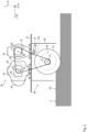
- the drive arrangement 39 includes a first diesel engine 52 and a second diesel engine 54, which are next to each other and with parallel ones in the cross-machine direction Q extending axes of rotation 56 and 58 of their crankshafts or output shafts, respectively, are arranged with elastic engine bearings 60 on the machine frame 12.
- a functional transmission 62 is arranged in the form of a transfer case, which is permanently coupled to the output shaft of the first diesel engine 52 for transmitting torque.
- a hydraulic pump 64 is arranged as a functional device and a further power receiver on an output, so that the hydraulic pump 64 can always be operated by the first diesel engine 52 via the functional transmission 62.
- a first switchable clutch 66 is arranged, with which a transmission of torque from the first diesel engine 52 can be interrupted or established. Due to the arrangement of the first switchable clutch 66 in the torque path of the first diesel engine 52 behind the functional transmission 62, the switching state of the first switchable clutch 66 has no effect on torque transmission from the first diesel engine 52 to the functional transmission 62.
- a second switchable clutch 68 is arranged, with which a transmission of torque from the second diesel engine 54 can be interrupted or established.
- a working gear 70 is arranged, which comprises a traction mechanism and, in the exemplary embodiment shown, more precisely as a non-positive belt gear.
- the working gear 70 includes three deflection rollers 72, 74 and 76 and a belt 78, which runs closed around the three deflection rollers 72, 74 and 76.
- a belt tensioner 79 ensures, in a manner known per se, sufficient tension on the belt 78 and thus sufficient contact pressure in the area where it wraps around the deflection roller in 72, 74 and 76.
- a first deflection roller 72 is included connected to the first diesel engine 52 for common rotation via the first switchable clutch 66
- a second deflection roller 74 is connected to the second diesel engine 52 for common rotation via the second switchable clutch 68
- a third deflection roller 78 is connected to the milling drum 32.
- the diameters of the three deflection rollers 72, 74 and 76 are selected so that between the first deflection roller 72 and the third deflection roller 76 there is a different transmission ratio, reducing the speed and translating the torque, than between the second deflection roller 74 and the third deflection roller 76.
- the Figures 1 to 3 are not to scale. It is merely intended to express that, for example, the second deflection roller 74 has a larger diameter than the first deflection roller 72, so that the speed of the second diesel engine 54 towards the milling drum 32 is reduced to a lesser extent than the speed of the first diesel engine 52. For example preferably the speed of the first diesel engine 52 on the milling axis R and thus on the milling drum 32 is reduced to a value between approximately one eighteenth and one twentieth. The speed of the second diesel engine 54 is reduced, for example, on the milling axis R and thus a milling drum 32 to a value between approximately one fourteenth and one sixteenth.
- the working gear 70 can have a further speed-reducing planetary gear 80 provided between the third deflection roller 76 and the milling drum 32, which contributes to the transmission ratios mentioned above.
- the different transmission ratios for the first and second diesel engines 52 and 54 are preferably implemented exclusively by the deflection rollers 72, 74 and 76.
- the planetary gear 80 always transmits torque from the third deflection roller 76 to the milling drum 32 with the same transmission ratio, regardless of which diesel engine is currently delivering the working drive power.
- Figure 3 is the arrangement of Figure 2 with the exception of the belt tensioner 79 shown in top view.
- first diesel engine 52 is connected to the functional transmission 62 or to the second switchable clutch 68 via a first elastic shaft connection 82 and that the second diesel engine 54 is connected via a second elastic shaft connection 84.
- the elastic shaft connection can be any device suitable for compensating for radial offset between the end regions of a rotating shaft, such as a cardan connection or an elastomeric coupling.
- the first switchable clutch 66 and the second Switchable clutch 68 can be connected in a rotationally fixed manner to the first deflection roller 72 or to the second deflection roller 74 via a rigid drive shaft 86 or 88.
- a second hydraulic pump 89 as a further functional device and as an even further power receiver can be arranged directly in the housing 90 of the functional transmission 62. This is even preferable.
- the two diesel engines 52 and 54 are arranged with a crankshaft running parallel to the machine transverse direction Q. This preferred arrangement applies not only to the present exemplary embodiment, but quite fundamentally.
- crankshafts of the two diesel engines 52 and 54 are arranged parallel to the milling axis R. Furthermore, in principle, the axes of rotation of all other rotating components of the working gear 70, i.e. the deflection rollers in 72, 74 and 76 as well as all other rotating components of the functional gear 62, are arranged parallel to one another and preferably both to the milling axis R and to the crankshafts of the diesel engines 52.
- the control panel 26, which acts as a control device, can operate the milling drum 32 in three different operating modes: the milling drum 32 is driven only by the first diesel engine 52, with the functional devices 64 and 89 mentioned as examples also being operated at the same time via the functional gear 62, for example at a lower speed requirement to the milling drum 32; a drive of the milling drum 32 only by the second diesel engine 54 with a higher speed requirement for the milling drum 32, in which case the first diesel engine 52 still operates the functional devices 64 and 89 mentioned by way of example via the functional gear 62; and a drive of the milling drum 32 by both diesel engines 52 and 54 together with particularly high power demands on the milling drum 32.
- the control device can independently select the operating modes by input via the operating display 27 by the machine operator, depending on how the machine operator assesses the properties, in particular the hardness, of the soil U to be processed, and at what milling depth and at what feed speed he wants to mill.
- the control device can itself determine properties of the soil to be processed from recorded operating parameter values and incorporate these results into the control of the milling drum 32 and/or the two diesel engines 52 and 54.
- corresponding databases can be stored in the control device, which link parameters characterizing the soil to be processed as well as the desired milling parameters feed speed and milling depth with operating parameters of the first and second diesel engines 52 and 54.
- the control device selects the operating modes, among other things, by appropriately switching the switchable clutches 66 and 68.
- the control device can first determine a target speed selected for the respective milling task for the first diesel engine 52. Since the control device can access a database in which the transmission ratio of the engine power of the first diesel engine 52 to the milling drum 32 is stored, the control device can choose from a desired one Speed of the milling drum 32 calculate the speed of the first diesel engine 52 required for this.
- the control device regulates the first diesel engine 52 to the determined target speed, with the control device detecting the speed of the first diesel engine 52 with the speed sensor 92 for this purpose.
- the control device detects the torque output by the first diesel engine 52 via the torque sensor 96, which can be arranged, for example, in the first switchable clutch 66.
- the control device then begins to regulate the second diesel engine 54 with regard to its torque.
- the control device uses the detected torque output by the first diesel engine 52 as a basis and reduces its amount by a predetermined amount.
- the reduction in the torque amount can be done additively by subtracting a predetermined torque difference, i.e. by adding a negative difference amount, or can be done multiplicatively by multiplying by a factor that is selected to be less than 1.
- the control device determines the amount of torque that the second diesel engine 54 should deliver. Using the torque sensor 98 in the second switchable clutch 68, the control device then regulates the diesel engine 54 so that it delivers the determined target torque.
- the second diesel engine 54 can also be speed-controlled like the first diesel engine 52.
- This control is also initially based on the target speed for the first diesel engine 52, which is determined for the first diesel engine 52 from the target milling drum speed. Based on the target milling drum speed, the control device also determines a target speed for the second diesel engine 54 based on the transmission ratio of the working gear 70 the second diesel engine 54. In the shown Embodiment example, the first diesel engine 52 always rotates faster than the second diesel engine 54 at the same milling drum speed.
- the two determined target speeds are finalized by the control device in order to obtain the most stable control operation possible.
- the difference in magnitude between the target speeds determined from the target milling drum speed is increased. This can be done, for example, by the control device increasing the target speed of the first diesel engine 52, for example by 15 rpm, or reducing the target speed of the second diesel engine 54, for example by 15 rpm, or both increasing the target speed of the first diesel engine 52 and the Target speed of the second diesel engine 54 is reduced, for example in order to increase the target speed difference by 15 rpm.
- the control device then regulates the first diesel engine 52 and the second diesel engine 54 to their finalized target speeds, using the speed sensors 92 and 94.
- the first diesel engine 52 is the always speed-controlled engine, on whose operation the control of the second diesel engine 54 is based.
- the second diesel engine 54 were always the speed-controlled engine with the same working gear 70, which is also possible, the first diesel engine 52 would be regulated according to one of the above methods in compliance with the control principles shown.
- the functional transmission 62 is permanently assigned to the first diesel engine 52 with the larger speed reduction ratio. Deviating from this, the functional transmission 62 can be permanently assigned to the second diesel engine 54 with the lower speed reduction ratio.
- the belt tensioner 79 can have a motor-driven roller 79a and can thus serve as a power take-off during maintenance work on the milling drum 32. This allows the milling drum to be rotated at low speed to visually inspect the outside of the milling drum and make repairs. to repair or replace components that require replacement, such as milling bits, bit holders or bit changing holders.
- milling operation is not possible with the belt tensioner 79 as a power take-off because the drive torque of the belt tensioner 79 is too low.
Landscapes
- Engineering & Computer Science (AREA)
- Mechanical Engineering (AREA)
- Combustion & Propulsion (AREA)
- Chemical & Material Sciences (AREA)
- Mining & Mineral Resources (AREA)
- Transportation (AREA)
- Architecture (AREA)
- Structural Engineering (AREA)
- Civil Engineering (AREA)
- General Engineering & Computer Science (AREA)
- Geology (AREA)
- Geochemistry & Mineralogy (AREA)
- General Life Sciences & Earth Sciences (AREA)
- Life Sciences & Earth Sciences (AREA)
- Agricultural Machines (AREA)
- Auxiliary Drives, Propulsion Controls, And Safety Devices (AREA)
- Operation Control Of Excavators (AREA)
Applications Claiming Priority (1)
| Application Number | Priority Date | Filing Date | Title |
|---|---|---|---|
| DE102022122472.4A DE102022122472B4 (de) | 2022-09-05 | 2022-09-05 | Selbstfahrende Bodenbearbeitungsmaschine mit Zwillingsmotoren und einem deren Leistung unterschiedlich übertragenden Arbeitsgetriebe |
Publications (3)
| Publication Number | Publication Date |
|---|---|
| EP4332304A1 true EP4332304A1 (fr) | 2024-03-06 |
| EP4332304B1 EP4332304B1 (fr) | 2025-12-31 |
| EP4332304C0 EP4332304C0 (fr) | 2025-12-31 |
Family
ID=87929371
Family Applications (1)
| Application Number | Title | Priority Date | Filing Date |
|---|---|---|---|
| EP23194878.7A Active EP4332304B1 (fr) | 2022-09-05 | 2023-09-01 | Machine automotrice de traitement du sol avec moteurs jumelés et procédé de fonctionnement de ladite machine |
Country Status (4)
| Country | Link |
|---|---|
| US (1) | US12553197B2 (fr) |
| EP (1) | EP4332304B1 (fr) |
| CN (1) | CN221218431U (fr) |
| DE (1) | DE102022122472B4 (fr) |
Citations (6)
| Publication number | Priority date | Publication date | Assignee | Title |
|---|---|---|---|---|
| DE102012006189A1 (de) | 2012-03-27 | 2013-10-02 | Bomag Gmbh | Antriebsvorrichtung in einer selbstfahrenden Baumaschine sowie Verfahren zum Einstellen eines Drehzahlverhältnisses bei einer derartigen Antriebsvorrichtung |
| EP1983105B1 (fr) | 2007-04-20 | 2013-10-09 | Wirtgen GmbH | Engin de travaux publics automoteur, en particulier machine de fraisage, recycleur ou stabilisateur |
| DE102012012738A1 (de) * | 2012-06-26 | 2014-01-02 | Bomag Gmbh | Bodenbearbeitungsmaschine |
| DE102015002743A1 (de) | 2014-12-23 | 2016-06-23 | Wirtgen Gmbh | Selbstfahrende Baumaschine und Verfahren zum Betreiben einer selbstfahrenden Baumaschine |
| DE202015004528U1 (de) * | 2015-04-27 | 2016-07-28 | Liebherr-Components Biberach Gmbh | Arbeitsmaschine mit leistungsverzweigbarem Antrieb |
| DE102015111249A1 (de) | 2015-07-10 | 2017-01-12 | Wirtgen Gmbh | Bodenbearbeitungsmaschine und Verfahren zum verschleißoptimierten Betrieb einer Bodenbearbeitungsmaschine |
Family Cites Families (2)
| Publication number | Priority date | Publication date | Assignee | Title |
|---|---|---|---|---|
| US3844184A (en) * | 1973-05-21 | 1974-10-29 | Dominion Eng Works Ltd | Load equalized transmission |
| DE102016010390A1 (de) * | 2016-08-30 | 2018-03-01 | Wirtgen Gmbh | Fräsmaschine und Verfahren zum Betrieb einer Fräsmaschine |
-
2022
- 2022-09-05 DE DE102022122472.4A patent/DE102022122472B4/de active Active
-
2023
- 2023-08-07 US US18/366,235 patent/US12553197B2/en active Active
- 2023-08-25 CN CN202322296571.1U patent/CN221218431U/zh not_active Withdrawn - After Issue
- 2023-09-01 EP EP23194878.7A patent/EP4332304B1/fr active Active
Patent Citations (6)
| Publication number | Priority date | Publication date | Assignee | Title |
|---|---|---|---|---|
| EP1983105B1 (fr) | 2007-04-20 | 2013-10-09 | Wirtgen GmbH | Engin de travaux publics automoteur, en particulier machine de fraisage, recycleur ou stabilisateur |
| DE102012006189A1 (de) | 2012-03-27 | 2013-10-02 | Bomag Gmbh | Antriebsvorrichtung in einer selbstfahrenden Baumaschine sowie Verfahren zum Einstellen eines Drehzahlverhältnisses bei einer derartigen Antriebsvorrichtung |
| DE102012012738A1 (de) * | 2012-06-26 | 2014-01-02 | Bomag Gmbh | Bodenbearbeitungsmaschine |
| DE102015002743A1 (de) | 2014-12-23 | 2016-06-23 | Wirtgen Gmbh | Selbstfahrende Baumaschine und Verfahren zum Betreiben einer selbstfahrenden Baumaschine |
| DE202015004528U1 (de) * | 2015-04-27 | 2016-07-28 | Liebherr-Components Biberach Gmbh | Arbeitsmaschine mit leistungsverzweigbarem Antrieb |
| DE102015111249A1 (de) | 2015-07-10 | 2017-01-12 | Wirtgen Gmbh | Bodenbearbeitungsmaschine und Verfahren zum verschleißoptimierten Betrieb einer Bodenbearbeitungsmaschine |
Also Published As
| Publication number | Publication date |
|---|---|
| EP4332304B1 (fr) | 2025-12-31 |
| EP4332304C0 (fr) | 2025-12-31 |
| DE102022122472A1 (de) | 2024-03-07 |
| CN221218431U (zh) | 2024-06-25 |
| CN117646377A (zh) | 2024-03-05 |
| DE102022122472B4 (de) | 2024-03-28 |
| US12553197B2 (en) | 2026-02-17 |
| US20240076840A1 (en) | 2024-03-07 |
Similar Documents
| Publication | Publication Date | Title |
|---|---|---|
| EP3456879B1 (fr) | Dispositif de compactage du sol | |
| EP0530546B1 (fr) | Appareil de compactage | |
| EP3719202B1 (fr) | Machine de traitement du sol | |
| WO2013143652A1 (fr) | Mécanisme d'entraînement dans un engin automoteur de chantier et procédé de réglage d'un rapport de vitesse de rotation dans un tel mécanisme d'entraînement | |
| DE102018206411B4 (de) | Antriebsstrang für eine elektrisch betriebene Arbeitsmaschine | |
| EP3901373B1 (fr) | Unité de remplacement destinée au traitement texturant de surface du sol et la machine de construction routière dotée d'une telle unité de remplacement | |
| DE102010010578B4 (de) | Hydrostatisch-elektrischer Antrieb, Flurförderfahrzeug mit einem solchen Antrieb | |
| EP2881516A1 (fr) | Compacteur routier | |
| EP3376067B1 (fr) | Machine de traitement du sol pourvue de transmission entre le moteur d'entraînement et le dispositif de travail rotatif | |
| EP3543058A1 (fr) | Transmission d'arbre de prise de force | |
| EP0563515B1 (fr) | Dispositif d'entraînement pour machines de chantier ou véhicules de chantier | |
| EP1806206A1 (fr) | Ponceuse de sol | |
| DE10319681A1 (de) | Verteilergetriebe mit mindestens drei Wellen | |
| DE102013110315A1 (de) | Landwirtschaftliche Arbeitsmaschine | |
| DE102022122472B4 (de) | Selbstfahrende Bodenbearbeitungsmaschine mit Zwillingsmotoren und einem deren Leistung unterschiedlich übertragenden Arbeitsgetriebe | |
| EP3901372B1 (fr) | Dispositif de compactage du sol pourvu d'essieu monté à commande électrique | |
| DE102020204383B4 (de) | Selbstfahrende Baumaschine | |
| DE102012025092B3 (de) | Antriebseinrichtung für ein Kraftfahrzeug | |
| DE102022119947A1 (de) | Fräsmaschine mit wärmetauscherkreislauf | |
| EP3767033B1 (fr) | Engin de construction automoteur et procédé de traitement des revêtements de sol | |
| EP3736158A1 (fr) | Agencement de boîte de prise de force | |
| DE102018132377A1 (de) | Bodenbearbeitungsmaschine | |
| DE102024106297A1 (de) | Traktor | |
| DE102024101809A1 (de) | Variator und variatorwelle | |
| EP4678437A1 (fr) | Agencement d'entraînement, essieu et machine de travail |
Legal Events
| Date | Code | Title | Description |
|---|---|---|---|
| PUAI | Public reference made under article 153(3) epc to a published international application that has entered the european phase |
Free format text: ORIGINAL CODE: 0009012 |
|
| STAA | Information on the status of an ep patent application or granted ep patent |
Free format text: STATUS: THE APPLICATION HAS BEEN PUBLISHED |
|
| AK | Designated contracting states |
Kind code of ref document: A1 Designated state(s): AL AT BE BG CH CY CZ DE DK EE ES FI FR GB GR HR HU IE IS IT LI LT LU LV MC ME MK MT NL NO PL PT RO RS SE SI SK SM TR |
|
| STAA | Information on the status of an ep patent application or granted ep patent |
Free format text: STATUS: REQUEST FOR EXAMINATION WAS MADE |
|
| 17P | Request for examination filed |
Effective date: 20240812 |
|
| RBV | Designated contracting states (corrected) |
Designated state(s): AL AT BE BG CH CY CZ DE DK EE ES FI FR GB GR HR HU IE IS IT LI LT LU LV MC ME MK MT NL NO PL PT RO RS SE SI SK SM TR |
|
| GRAP | Despatch of communication of intention to grant a patent |
Free format text: ORIGINAL CODE: EPIDOSNIGR1 |
|
| STAA | Information on the status of an ep patent application or granted ep patent |
Free format text: STATUS: GRANT OF PATENT IS INTENDED |
|
| GRAJ | Information related to disapproval of communication of intention to grant by the applicant or resumption of examination proceedings by the epo deleted |
Free format text: ORIGINAL CODE: EPIDOSDIGR1 |
|
| STAA | Information on the status of an ep patent application or granted ep patent |
Free format text: STATUS: REQUEST FOR EXAMINATION WAS MADE |
|
| GRAP | Despatch of communication of intention to grant a patent |
Free format text: ORIGINAL CODE: EPIDOSNIGR1 |
|
| STAA | Information on the status of an ep patent application or granted ep patent |
Free format text: STATUS: GRANT OF PATENT IS INTENDED |
|
| GRAS | Grant fee paid |
Free format text: ORIGINAL CODE: EPIDOSNIGR3 |
|
| GRAA | (expected) grant |
Free format text: ORIGINAL CODE: 0009210 |
|
| STAA | Information on the status of an ep patent application or granted ep patent |
Free format text: STATUS: THE PATENT HAS BEEN GRANTED |
|
| INTG | Intention to grant announced |
Effective date: 20251031 |
|
| INTC | Intention to grant announced (deleted) | ||
| INTG | Intention to grant announced |
Effective date: 20251119 |
|
| AK | Designated contracting states |
Kind code of ref document: B1 Designated state(s): AL AT BE BG CH CY CZ DE DK EE ES FI FR GB GR HR HU IE IS IT LI LT LU LV MC ME MK MT NL NO PL PT RO RS SE SI SK SM TR |
|
| REG | Reference to a national code |
Ref country code: CH Ref legal event code: F10 Free format text: ST27 STATUS EVENT CODE: U-0-0-F10-F00 (AS PROVIDED BY THE NATIONAL OFFICE) Effective date: 20251231 Ref country code: GB Ref legal event code: FG4D Free format text: NOT ENGLISH |
|
| REG | Reference to a national code |
Ref country code: DE Ref legal event code: R096 Ref document number: 502023002632 Country of ref document: DE |
|
| REG | Reference to a national code |
Ref country code: IE Ref legal event code: FG4D Free format text: LANGUAGE OF EP DOCUMENT: GERMAN |
|
| U01 | Request for unitary effect filed |
Effective date: 20260107 |
|
| U07 | Unitary effect registered |
Designated state(s): AT BE BG DE DK EE FI FR IT LT LU LV MT NL PT RO SE SI Effective date: 20260114 |
|
| PG25 | Lapsed in a contracting state [announced via postgrant information from national office to epo] |
Ref country code: NO Free format text: LAPSE BECAUSE OF FAILURE TO SUBMIT A TRANSLATION OF THE DESCRIPTION OR TO PAY THE FEE WITHIN THE PRESCRIBED TIME-LIMIT Effective date: 20260331 |
|
| PG25 | Lapsed in a contracting state [announced via postgrant information from national office to epo] |
Ref country code: HR Free format text: LAPSE BECAUSE OF FAILURE TO SUBMIT A TRANSLATION OF THE DESCRIPTION OR TO PAY THE FEE WITHIN THE PRESCRIBED TIME-LIMIT Effective date: 20251231 |
|
| PG25 | Lapsed in a contracting state [announced via postgrant information from national office to epo] |
Ref country code: RS Free format text: LAPSE BECAUSE OF FAILURE TO SUBMIT A TRANSLATION OF THE DESCRIPTION OR TO PAY THE FEE WITHIN THE PRESCRIBED TIME-LIMIT Effective date: 20260331 |