EP4332305A1 - Schneckenanordnung und schneefräse - Google Patents
Schneckenanordnung und schneefräse Download PDFInfo
- Publication number
- EP4332305A1 EP4332305A1 EP23193690.7A EP23193690A EP4332305A1 EP 4332305 A1 EP4332305 A1 EP 4332305A1 EP 23193690 A EP23193690 A EP 23193690A EP 4332305 A1 EP4332305 A1 EP 4332305A1
- Authority
- EP
- European Patent Office
- Prior art keywords
- supporting shaft
- snow
- paddle
- auger assembly
- connecting part
- Prior art date
- Legal status (The legal status is an assumption and is not a legal conclusion. Google has not performed a legal analysis and makes no representation as to the accuracy of the status listed.)
- Granted
Links
Images




Classifications
-
- E—FIXED CONSTRUCTIONS
- E01—CONSTRUCTION OF ROADS, RAILWAYS, OR BRIDGES
- E01H—STREET CLEANING; CLEANING OF PERMANENT WAYS; CLEANING BEACHES; DISPERSING OR PREVENTING FOG IN GENERAL CLEANING STREET OR RAILWAY FURNITURE OR TUNNEL WALLS
- E01H5/00—Removing snow or ice from roads or like surfaces; Grading or roughening snow or ice
- E01H5/04—Apparatus propelled by animal or engine power; Apparatus propelled by hand with driven dislodging or conveying levelling elements, conveying pneumatically for the dislodged material
- E01H5/045—Means per se for conveying or discharging the dislodged material, e.g. rotary impellers, discharge chutes
-
- E—FIXED CONSTRUCTIONS
- E01—CONSTRUCTION OF ROADS, RAILWAYS, OR BRIDGES
- E01H—STREET CLEANING; CLEANING OF PERMANENT WAYS; CLEANING BEACHES; DISPERSING OR PREVENTING FOG IN GENERAL CLEANING STREET OR RAILWAY FURNITURE OR TUNNEL WALLS
- E01H5/00—Removing snow or ice from roads or like surfaces; Grading or roughening snow or ice
- E01H5/04—Apparatus propelled by animal or engine power; Apparatus propelled by hand with driven dislodging or conveying levelling elements, conveying pneumatically for the dislodged material
- E01H5/08—Apparatus propelled by animal or engine power; Apparatus propelled by hand with driven dislodging or conveying levelling elements, conveying pneumatically for the dislodged material dislodging essentially by driven elements
- E01H5/09—Apparatus propelled by animal or engine power; Apparatus propelled by hand with driven dislodging or conveying levelling elements, conveying pneumatically for the dislodged material dislodging essentially by driven elements the elements being rotary or moving along a closed circular path, e.g. rotary cutter, digging wheels
- E01H5/098—Apparatus propelled by animal or engine power; Apparatus propelled by hand with driven dislodging or conveying levelling elements, conveying pneumatically for the dislodged material dislodging essentially by driven elements the elements being rotary or moving along a closed circular path, e.g. rotary cutter, digging wheels about horizontal or substantially horizontal axises perpendicular or substantially perpendicular to the direction of clearing
Definitions
- the disclosure relates to a field of snow thrower, and in particular, relates to an auger assembly of a snow thrower.
- a snow thrower operates by gathering the snow on the surface of a road using its snow scraper, and then throw the gathered snow away from the road using its snow throwing paddle.
- the conventional snow throwers may have the following defects: 1. their augers may have a lot of parts and components that need to be tiresomely assembled, resulting the thrown snow not being gathered around or concentrated; 2. their augers are easy to bend and deform when throwing snow under high force, resulting in poor snow throwing effect; 3. the snow collecting and snow throwing parts of these auger are made of rubber, which may cause the rubber to deform easily when the snow is thrown under high force, resulting in low snow-throwing efficiency; 4. the area ratios between the snow throwing part and the snow collecting part of the auger are not suitable, which may result in a large snow throwing load, and may cause the snow not be thrown far away.
- the present disclosure provides an auger assembly and a snow thrower with reliable structural strength.
- an auger assembly that includes: a supporting shaft; a snow throwing paddle, a left snow scraper assembly and a right snow scraper assembly.
- the snow throwing paddle is mounted in a middle of the supporting shaft and assembled to rotate synchronously with the supporting shaft.
- the left snow scraper assembly respectively and the right snow scraper assembly are located on two sides of the snow throwing paddle and are symmetrical to each other with respect to a particular plane that is perpendicular to an axis of the supporting shaft.
- the left snow scraper assembly includes a snow scraper, and the snow scraper is helically spiraled around the supporting shaft along an axial direction of the supporting shaft.
- the snow scraper is spliced by at least two-section split helical blades, and each section of the helical blade includes a connecting part located at an end that is away from the snow throwing paddle.
- the connecting part is connected with the supporting shaft.
- One of the helical blades closest to the snow throwing paddle is connected with the snow throwing paddle.
- the left snow scraper assembly includes at least two snow scrapers, and each of the snow scrapers is evenly arranged with a specific interval along a circumferential direction of the supporting shaft, and each helical blade of each snow scraper located in a same section in the axial direction of the supporting shaft shares the same connecting part.
- the helical blade and the connecting part are of an integral structure.
- a depressed part is formed on the connecting part which is closest to an end of the supporting shaft, the depressed part is located around the supporting shaft, and the depressed part is caved toward a direction away from the end of the supporting shaft.
- its arc center angle is an angle corresponding to an outermost arc profile related to this specific helical blade.
- a sum of an arc center angles for all helical blades corresponding to an outermost arc profile of each helical blade is greater than or equal to 100° and less than or equal to 360°.
- a shape of an area, which is connected with the helical blade that is on the connecting part closest to the end of the supporting shaft is a planar structure and is perpendicular to the axis of the supporting shaft. And the shape of the area, which is connected with the helical blade on the other connecting parts, are twisted into a shape consistent with the helical blade.
- the snow throwing paddle includes at least two paddles, and the paddles are cantilevered along a radial direction of the supporting shaft, a central area on a front side of the paddle in a rotation direction is depressed toward a rear side in the rotation direction, and left and right ends of the paddle in the front side in the rotation direction are warped toward the front side in the rotation direction.
- a through hole is arranged on the paddle near the supporting shaft.
- the paddle is provided with a rubber plate, the rubber plate is detachably connected with the paddle, and protrudes from an edge of the paddle along the radial direction of the supporting shaft.
- the paddles are formed as an integrated structure, and a shaft hole is arranged between the paddles to enable the supporting shaft to pass through, a radial hole is arranged on a side wall of the shaft hole and the supporting shaft, and a positioning bolt is arranged in the radial hole.
- a flanged edge is arranged on an edge of the paddle along the radial direction of the supporting shaft away from the supporting shaft, and the flanged edge protrudes backward in the rotation direction of the paddle.
- a ratio between a length of the snow throwing paddle and a length of the left snow scraper assembly is greater than or equal to 0.1 and less than or equal to 2.5.
- a ratio between a maximum diameter of a projection of the auger assembly in the axial direction of the supporting shaft and a length of the supporting shaft is greater than or equal to 0.1 and less than or equal to 1.
- an outer edge of the snow scraper is provided with a sawtooth cut or a bending flange.
- the disclosure further provides the snow thrower.
- the snow thrower includes a main body and an auger assembly.
- the main body is provided with a driving device.
- the auger assembly mounted on a front end of the main body and includes a supporting shaft; a snow throwing paddle, a left snow scraper assembly and a right snow scraper assembly.
- the supporting shaft is connected with the driving device using a transmission mechanism.
- the snow throwing paddle is mounted in a middle of the supporting shaft and assembled to rotate synchronously with the supporting shaft.
- the left snow scraper assembly and the right snow scraper assembly are located on two sides of the snow throwing paddle respectively and are symmetrical to each other with respect to a particular plane that is perpendicular to an axis of the supporting shaft.
- the left snow scraper assembly includes a snow scraper, and the snow scraper is helically spiraled around the supporting shaft along an axial direction of the supporting shaft.
- the snow scraper is spliced by at least two-section split helical blades, and each section of the helical blade includes a connecting part located at an end that is away from the snow throwing paddle.
- the connecting part is connected with the supporting shaft.
- One of the helical blades closest to the snow throwing paddle is connected with the snow throwing paddle.
- the snow scraper of the present disclosure is configured as a multi-section structure, a connecting part is arranged at ends of each section of the helical blade, and an inner-most helical blade is fixedly connected with the snow throwing paddle, so that both ends of each section of the helical blade are effectively fixed, which avoids a problem of bending deformation caused by long spans, and improves a structural strength of the auger assembly.
- the two helical blades that are located at the same axial position may form an integrated structure with the same connecting part 32, the two helical blades and one connecting part form a single component, creating a modular design of the snow scraper that simplifies the assembly structure, improves assembly efficiency, and facilitates easy maintenance of the snow scraper.
- a structure of the snow throwing paddle of the disclosure can enable a throwing path to be more concentrated and improve snow throwing efficiency; when there is too much snow accumulated in a middle of the supporting shaft, part of the snow on the front side in the rotation direction of the paddle may overflow to the rear side in the rotation direction of the paddle through the through hole, so as to avoid overloading of the snow throwing paddle.
- drawings provided in the embodiments are for illustrative of a basic idea of the disclosure.
- the drawings may show assemblies related to the disclosure instead of drawing according to the number, shape and size of the assemblies in actual implementation.
- the type, quantity and ratio of each assembly may be changed at will, and a layout of the assemblies may also be more complicated.
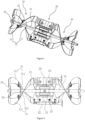
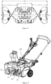
- FIG. 1 through FIG. 14 A technical solution of the present disclosure may be described in detail below, which may be operative in combination with a walk-behind snow thrower. It should be understood that the disclosure may be implemented an improvement on an auger part of the snow thrower, so no special requirement is needed on the type of walking mode the snow thrower is under. In other words, the auger assembly of the present disclosure may be applicable to any walk-behind snow throwers, and may also be applied to any ride-on snow throwers, hand-held snow throwers and the like.
- a walk-behind snow thrower may include a main body 100 and an auger assembly.
- the main body 100 may be implemented with a driving device.
- the driving device is configured to drive the rotating of the auger assembly.
- the walk-behind snow thrower may also include a walking device and a control device.
- the control device may be arranged on, e.g., a handle of the snow thrower.
- the walking device and the auger assembly may share a common power source, or each of which may be equipped with its own independent power sources.
- the power source may be, for example, an internal combustion engine or an electrical motor.
- the snow thrower may also be equipped with a comparable power module, such as a battery pack.
- the auger assembly is mounted on a front end of the main body 100, and the auger assembly includes a supporting shaft 10, a snow throwing paddle 20, a left snow scraper assembly 30, and a right snow scraper assembly 40.
- the front end of the main body 100 may contain an auger housing for accommodating the auger assembly.
- a front end of the auger housing may have an opening for gathering snow, and the rear part and the top part of the auger assembly may be surrounded by the auger housing to prevent the snow from splashing.
- An upper end of the auger housing may have a snow throwing path/tunnel for guiding the direction of the snow throwing.
- the supporting shaft 10 may be connected with the driving device using a transmission mechanism. It should be understood that, any connection mechanism for the transmission may be feasible, including e.g., gear transmission, pulley transmission and the like.
- the snow throwing paddle 20 is mounted in a center of the supporting shaft 10 and is assembled to be able to rotate synchronously with the supporting shaft 10.
- the left snow scraper assembly 30 and the right snow scraper assembly 40 are located on two sides of the snow throwing paddle, and are symmetrical to each other with respect to a particular plane that is perpendicular to an axis of the supporting shaft 10.
- the particular plane may be, for example, a plane at a center of the supporting shaft 10.
- structures of the right snow scraper assembly 40 and the left snow scraper assembly 30 are substantially symmetrical, so the following content mainly describes the structure of the left snow scraper in detail.
- the left snow scraper assembly 30 includes a snow scraper 31, and the snow scraper 31 is helically spiraled around the supporting shaft 10 along an axial direction of the supporting shaft 10.
- the snow scraper 31 is spliced/jointed by at least two-section split helical blades 311, and each section of the helical blade 311 includes a connecting part 32 located at an end that is away from the snow throwing paddle 20.
- the connecting part 32 may be connected with the supporting shaft 10.
- One of the helical blades 311 closest to the snow throwing paddle 20 is connected with the snow throwing paddle 20.
- the part where the helical blade 311 is connected with the snow blowing paddle 20 is the end away from the connecting part 32.
- the disclosure Comparing with a single-structure auger, the disclosure provides the snow scraper 31 with a multi-section structure, and provides the connecting part 32 at an end of each section of the blade.
- An inner-most blade is fixedly connected with the snow throwing paddle 20, so that both ends of each blade are effectively fixed, which avoids bending and deformation caused by long spans, and improves a structural strength of the auger assembly.
- each snow scraper 31 is evenly arranged with a specific interval along a circumferential direction of the supporting shaft 10, and each helical blade 311 of each snow scraper 31 located in the same section in the axial direction of the supporting shaft 10 shares the same connecting part 32.
- each snow scraper 31 is formed by sequentially connecting two helical blades 311, which means that the left snow scraper assembly 30 of this embodiment includes a total of four helical blades 311.
- the snow scrapers 31 of the disclosure are not limited to two, and may have for example, three or more.
- the helical blade 311 and the connecting part 32 are integrally structured.
- the two helical blades 311 that are located at the same axial position may form an integrated structure with the same connecting part 32.
- the two helical blades 311 and one connecting part 32 may form a single component, creating a modular design of the snow scraper 31 that simplifies the assembly structure, improves assembly efficiency, and facilitates easy maintenance of the snow scraper 31.
- a depressed part 321 is formed on the connecting part 32 closest to an end of the supporting shaft 10, the depressed part 321 is located around the supporting shaft 10, and the depressed part 321 is caved toward a direction that is away from the end of the supporting shaft 10. It should be understood that the depressed part 321 can avoid an interference with the connection structure at the end of the supporting shaft 10, so that the snow scraper 31 may be as close as possible to both ends of the auger housing, thereby avoiding dead spots in snow cleaning.
- its arc center angle may be an angle corresponding to an outermost arc profile related to this specific helical blade 311.
- the sum of the arc center angles for all helical blades 311 may be greater than or equal to 100° and less than or equal to 360°.
- ⁇ 1 and ⁇ 2 may be the corresponding two arc center angles for the two helical blades 311, and 100° ⁇ ⁇ 1 + ⁇ 2 ⁇ 360°.
- ⁇ 1 and ⁇ 2 may be the two arc center angles for the two helical blades 311, and 100° ⁇ 1 + ⁇ 2 ⁇ 360°.
- a sum of an arc center angles of the above two sections can be greater than 360°, thereby realizing a continuous cutting and transmission of snow.
- a sheet thickness t of the snow scraper 31 may be from 0.8mm to 5mm.
- the shape of an area, which is connected with the helical blade 311 that is on the connecting part 32 closest to the end of the supporting shaft 10, may have a planar/flat structure and is perpendicular to the axis of the supporting shaft 10. And the shape of the area, which is connected with the helical blade 311 on the remaining connecting parts 32, are twisted into a shape consistent with the helical blade 311, such an approach ensures that a surface of an auger is smooth to prevent snow from accumulating on the auger.
- the area connected to the helical blade 311 on the connecting part 32 closest to the end of the supporting shaft 10 is set as a plane so as to ensure that the connecting part 32 is adapted to an inner wall of the auger housing, and a gap between the connecting part 32 and the inner wall is reduced.
- this area may have any shape that is not flat.
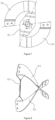
- the snow throwing paddle 20 includes at least two paddles 21, and the paddles 21 are cantilevered along a radial direction of the supporting shaft 10.
- a central area on a front side of the paddle 21 in a rotation direction is depressed/caved toward a rear side in the rotation direction, and left and right ends of the paddle 21 in the front side in the rotation direction are warped toward the front side in the rotation direction.
- the rotation direction in the disclosure refers to a rotation direction of the auger assembly during operation of the snow thrower, and a structure of the snow throwing paddle 20 in the above form can enable throwing paths to be more concentrated, thereby improve snow throwing efficiency.
- a through hole 23 is arranged on the paddle 21 near the supporting shaft 10.
- part of the snow accumulated on the front side of the paddle 21 in the rotation direction may overflow/run-off to the rear side of the paddle 21 in the rotation direction through the through hole 23, thereby preventing the paddle 21 from being overloaded.
- the paddle 21 is provided with a rubber plate 22.
- the rubber plate 22 is detachably connected with the paddle 21, and protrudes from an edge of the paddle 21 along the radial direction of the supporting shaft 10.
- a length H of the rubber plate 22 protruding from the edge of the paddle 21 satisfies the following conditions: H is more than or equal to 3mm and less than or equal to 30mm. In some embodiments, H may be around 15mm. A sufficient allowance may be preserved between the rubber plate 22 and the paddle 21 to ensure a duration life of the paddle 21.
- the two paddles 21 may be formed as an integrated structure, and a shaft hole is arranged between the paddles 21 to enable the supporting shaft 10 to pass through.
- a radial hole is arranged on a side wall of the shaft hole and the supporting shaft 10, and a positioning bolt 11 is arranged in the radial hole.
- the snow throwing paddle may be formed by e.g., pressing different parts together into one piece.
- the snow throwing paddle has a simple structure and is easy to assemble.
- a flanged edge 24 is arranged on an edge of the paddle 21 along the radial direction of the supporting shaft 10 away from the supporting shaft 10, and the flanged edge 24 protrudes backward in the rotation direction of the paddle 21.
- the flanged edge 24 can strengthen a force-bearing area of the paddle 21 and may prevent the paddle 21 from being deformed.
- a ratio between a length L2 of the snow throwing paddle 20 and a length L1 of the left snow scraper assembly 31 may be greater than or equal to 0.1 and less than or equal to 2.5, which is reflected in FIG. 13 as being 0.1 ⁇ L2/L1 ⁇ 2.5.
- a ratio between a maximum diameter ⁇ 1 of a projection of the auger assembly along the axial direction of the supporting shaft 10 and a length L0 of the supporting shaft 10, may be greater than or equal to 0.1 and less than or equal to 1, which is reflected in FIG. 3 and FIG. 13 as being 0.1 ⁇ ⁇ 1/L0 ⁇ 1.
- the proportional relationships among the different parts provided in this disclosure can ensure working efficiency of the snow scraper 31, allow the snow throwing paddle 20 to be adapted to each other, enable an amount of collected snow and an amount of thrown snow to be in a roughly balanced state, and prevent the snow throwing paddle 20 from being overloaded or under-loaded.
- an outer edge of the snow scraper 31 may be provided with a sawtooth cut or a bending flange, or a concave-convex structure may be arranged on the snow scraper 31 to further improve the structural strength of the snow scraper 31.
- the snow scraper 31 of the present disclosure is further configured as a multi-section structure.
- a connecting part 32 is arranged at the end of each section of the helical blade, and an inner-most helical blade is fixedly connected with the snow throwing paddle 20, so that both ends of each section of the helical blade are effectively fixed, which reduces/minimizes the problem of bending deformation caused by long spans, and improves the structural strength of the auger assembly.
- the two helical blades 311 at the same axial position and the same connecting part 32 form an integrated structure
- the two helical blades 311 and one connecting part 32 may form a single component, creating a modular design of the snow scraper 31 that simplifies the assembly structure, improves assembly efficiency, and facilitates easy maintenance of the snow scraper 31.
- a structure of the snow throwing paddle 20 of the disclosure can enable a throwing path to be more concentrated and improve snow throwing efficiency.
- part of the snow on the front side in the rotation direction of the paddle 21 may overflow/run-off to the rear side in the rotation direction of the paddle 21 through the through hole 23, so as to avoid overloading of the snow throwing paddle 20.
Landscapes
- Engineering & Computer Science (AREA)
- Architecture (AREA)
- Civil Engineering (AREA)
- Structural Engineering (AREA)
- Cleaning Of Streets, Tracks, Or Beaches (AREA)
Applications Claiming Priority (2)
| Application Number | Priority Date | Filing Date | Title |
|---|---|---|---|
| CN202222284783.3U CN217948921U (zh) | 2022-08-29 | 2022-08-29 | 一种滚雪刀组件及扫雪机 |
| CN202211042802.XA CN115262463B (zh) | 2022-08-29 | 2022-08-29 | 一种滚雪刀组件及扫雪机 |
Publications (2)
| Publication Number | Publication Date |
|---|---|
| EP4332305A1 true EP4332305A1 (de) | 2024-03-06 |
| EP4332305B1 EP4332305B1 (de) | 2026-04-08 |
Family
ID=87576019
Family Applications (1)
| Application Number | Title | Priority Date | Filing Date |
|---|---|---|---|
| EP23193690.7A Active EP4332305B1 (de) | 2022-08-29 | 2023-08-28 | Schneckenanordnung und schneefräse |
Country Status (3)
| Country | Link |
|---|---|
| US (1) | US20240068191A1 (de) |
| EP (1) | EP4332305B1 (de) |
| CA (1) | CA3209625A1 (de) |
Citations (4)
| Publication number | Priority date | Publication date | Assignee | Title |
|---|---|---|---|---|
| CA2301358C (en) * | 2000-03-20 | 2007-05-22 | Honda Giken Kogyo Kabushiki Kaisha | Snow shoveling machine |
| US20180334781A1 (en) * | 2017-05-16 | 2018-11-22 | Nanjing Chervon Industry Co., Ltd. | Auger for a snow thrower |
| US20190194892A1 (en) * | 2017-12-27 | 2019-06-27 | The Toro Company | Rotor for snow thrower |
| US20190264405A1 (en) * | 2018-02-28 | 2019-08-29 | The Toro Company | Snowthrower housing incorporating bypass and auger for use with same |
Family Cites Families (4)
| Publication number | Priority date | Publication date | Assignee | Title |
|---|---|---|---|---|
| JPH0235107A (ja) * | 1988-07-22 | 1990-02-05 | Honda Motor Co Ltd | 除雪機のオーガパドル |
| CN2659953Y (zh) * | 2003-08-25 | 2004-12-01 | 苏州美瑞机械制造有限公司 | 扫雪机刮雪刀装置 |
| US9546462B2 (en) * | 2014-11-19 | 2017-01-17 | The Toro Company | Rotor and rotor housing for a snowthrower |
| CN110644414A (zh) * | 2019-10-29 | 2020-01-03 | 宁海县宜宜园林工具有限公司 | 扫雪机转子总成 |
-
2023
- 2023-08-09 US US18/447,285 patent/US20240068191A1/en active Pending
- 2023-08-17 CA CA3209625A patent/CA3209625A1/en active Pending
- 2023-08-28 EP EP23193690.7A patent/EP4332305B1/de active Active
Patent Citations (4)
| Publication number | Priority date | Publication date | Assignee | Title |
|---|---|---|---|---|
| CA2301358C (en) * | 2000-03-20 | 2007-05-22 | Honda Giken Kogyo Kabushiki Kaisha | Snow shoveling machine |
| US20180334781A1 (en) * | 2017-05-16 | 2018-11-22 | Nanjing Chervon Industry Co., Ltd. | Auger for a snow thrower |
| US20190194892A1 (en) * | 2017-12-27 | 2019-06-27 | The Toro Company | Rotor for snow thrower |
| US20190264405A1 (en) * | 2018-02-28 | 2019-08-29 | The Toro Company | Snowthrower housing incorporating bypass and auger for use with same |
Also Published As
| Publication number | Publication date |
|---|---|
| US20240068191A1 (en) | 2024-02-29 |
| EP4332305B1 (de) | 2026-04-08 |
| CA3209625A1 (en) | 2024-02-29 |
Similar Documents
| Publication | Publication Date | Title |
|---|---|---|
| EP0214923A2 (de) | Einfach wirkende Schneefräse | |
| EP4321072B1 (de) | Bodenbürstenanordnung für staubsauger und staubsauger | |
| CN113519263A (zh) | 一种割草机及其刀片组件 | |
| EP1740775A2 (de) | Förderschnecke für schneeschleudermaschine | |
| DE19805857A1 (de) | Motorangetriebene Schneidemaschine und Zentrifugalkupplung hierfür | |
| EP4332305A1 (de) | Schneckenanordnung und schneefräse | |
| CN217948921U (zh) | 一种滚雪刀组件及扫雪机 | |
| US11753785B2 (en) | Snow plough | |
| CN115262463B (zh) | 一种滚雪刀组件及扫雪机 | |
| KR102206601B1 (ko) | 비산재 및 분체 고속 혼합기 | |
| CN110235592A (zh) | 割草机及其动力传动系统 | |
| CN220776566U (zh) | 果穗箱跑步机以及果穗箱 | |
| KR20080107332A (ko) | 구동축을 분리 구성하는 원형톱날 | |
| US20250347071A1 (en) | Auger device of snowplow | |
| CN209693498U (zh) | 一种拉茎辊装置和葵花割台 | |
| CN220134534U (zh) | 一种用于食品加工机的主机及食品加工机 | |
| KR101438318B1 (ko) | 양날회전이 가능한 예초기 칼날 구동장치 및 칼날 구동 방법 | |
| CN103875354A (zh) | 联合收割机的收割装置 | |
| CN221230334U (zh) | 一种高混一体机两片桨 | |
| CN214964787U (zh) | 一种方便清洗的食品加工机 | |
| US20240011232A1 (en) | Snow thrower and steering method thereof | |
| JPH0449866Y2 (de) | ||
| KR200432379Y1 (ko) | 관리기 부착형 복식 예취기 | |
| JP2004360377A (ja) | 除雪機 | |
| CN118661556A (zh) | 一种用于割草机的传动结构及割草机 |
Legal Events
| Date | Code | Title | Description |
|---|---|---|---|
| PUAI | Public reference made under article 153(3) epc to a published international application that has entered the european phase |
Free format text: ORIGINAL CODE: 0009012 |
|
| STAA | Information on the status of an ep patent application or granted ep patent |
Free format text: STATUS: THE APPLICATION HAS BEEN PUBLISHED |
|
| AK | Designated contracting states |
Kind code of ref document: A1 Designated state(s): AL AT BE BG CH CY CZ DE DK EE ES FI FR GB GR HR HU IE IS IT LI LT LU LV MC ME MK MT NL NO PL PT RO RS SE SI SK SM TR |
|
| STAA | Information on the status of an ep patent application or granted ep patent |
Free format text: STATUS: REQUEST FOR EXAMINATION WAS MADE |
|
| 17P | Request for examination filed |
Effective date: 20240902 |
|
| RBV | Designated contracting states (corrected) |
Designated state(s): AL AT BE BG CH CY CZ DE DK EE ES FI FR GB GR HR HU IE IS IT LI LT LU LV MC ME MK MT NL NO PL PT RO RS SE SI SK SM TR |
|
| GRAP | Despatch of communication of intention to grant a patent |
Free format text: ORIGINAL CODE: EPIDOSNIGR1 |
|
| STAA | Information on the status of an ep patent application or granted ep patent |
Free format text: STATUS: GRANT OF PATENT IS INTENDED |
|
| GRAS | Grant fee paid |
Free format text: ORIGINAL CODE: EPIDOSNIGR3 |
|
| INTG | Intention to grant announced |
Effective date: 20260129 |
|
| GRAA | (expected) grant |
Free format text: ORIGINAL CODE: 0009210 |
|
| STAA | Information on the status of an ep patent application or granted ep patent |
Free format text: STATUS: THE PATENT HAS BEEN GRANTED |
|
| AK | Designated contracting states |
Kind code of ref document: B1 Designated state(s): AL AT BE BG CH CY CZ DE DK EE ES FI FR GB GR HR HU IE IS IT LI LT LU LV MC ME MK MT NL NO PL PT RO RS SE SI SK SM TR |
|
| REG | Reference to a national code |
Ref country code: CH Ref legal event code: F10 Free format text: ST27 STATUS EVENT CODE: U-0-0-F10-F00 (AS PROVIDED BY THE NATIONAL OFFICE) Effective date: 20260408 Ref country code: GB Ref legal event code: FG4D |
|
| REG | Reference to a national code |
Ref country code: DE Ref legal event code: R096 Ref document number: 602023014776 Country of ref document: DE Ref country code: CH Ref legal event code: W10 Free format text: ST27 STATUS EVENT CODE: U-0-0-W10-W00 (AS PROVIDED BY THE NATIONAL OFFICE) Effective date: 20260430 |