EP4332322A2 - Bodenplatte und bodenplattenanordnungsverfahren - Google Patents
Bodenplatte und bodenplattenanordnungsverfahren Download PDFInfo
- Publication number
- EP4332322A2 EP4332322A2 EP23193654.3A EP23193654A EP4332322A2 EP 4332322 A2 EP4332322 A2 EP 4332322A2 EP 23193654 A EP23193654 A EP 23193654A EP 4332322 A2 EP4332322 A2 EP 4332322A2
- Authority
- EP
- European Patent Office
- Prior art keywords
- floor
- floor panel
- grooves
- receiving element
- vertical
- Prior art date
- Legal status (The legal status is an assumption and is not a legal conclusion. Google has not performed a legal analysis and makes no representation as to the accuracy of the status listed.)
- Pending
Links
- 238000000034 method Methods 0.000 title claims description 10
- 238000009434 installation Methods 0.000 claims abstract description 25
- 238000009408 flooring Methods 0.000 claims abstract description 24
- 230000007704 transition Effects 0.000 claims description 3
- 239000000463 material Substances 0.000 claims description 2
- 238000005520 cutting process Methods 0.000 description 10
- 238000009413 insulation Methods 0.000 description 3
- 238000007373 indentation Methods 0.000 description 2
- 239000000853 adhesive Substances 0.000 description 1
- 230000001070 adhesive effect Effects 0.000 description 1
- 238000010276 construction Methods 0.000 description 1
- 239000012535 impurity Substances 0.000 description 1
- 239000002245 particle Substances 0.000 description 1
- 238000010094 polymer processing Methods 0.000 description 1
- 238000009417 prefabrication Methods 0.000 description 1
- 239000000758 substrate Substances 0.000 description 1
Images


Classifications
-
- E—FIXED CONSTRUCTIONS
- E04—BUILDING
- E04F—FINISHING WORK ON BUILDINGS, e.g. STAIRS, FLOORS
- E04F15/00—Flooring
- E04F15/02—Flooring or floor layers composed of a number of similar elements
- E04F15/02038—Flooring or floor layers composed of a number of similar elements characterised by tongue and groove connections between neighbouring flooring elements
-
- E—FIXED CONSTRUCTIONS
- E04—BUILDING
- E04F—FINISHING WORK ON BUILDINGS, e.g. STAIRS, FLOORS
- E04F15/00—Flooring
- E04F15/02—Flooring or floor layers composed of a number of similar elements
- E04F15/02005—Construction of joints, e.g. dividing strips
-
- E—FIXED CONSTRUCTIONS
- E04—BUILDING
- E04F—FINISHING WORK ON BUILDINGS, e.g. STAIRS, FLOORS
- E04F2201/00—Joining sheets or plates or panels
- E04F2201/01—Joining sheets, plates or panels with edges in abutting relationship
- E04F2201/0153—Joining sheets, plates or panels with edges in abutting relationship by rotating the sheets, plates or panels around an axis which is parallel to the abutting edges, possibly combined with a sliding movement
-
- E—FIXED CONSTRUCTIONS
- E04—BUILDING
- E04F—FINISHING WORK ON BUILDINGS, e.g. STAIRS, FLOORS
- E04F2203/00—Specially structured or shaped covering, lining or flooring elements not otherwise provided for
- E04F2203/08—Specially structured or shaped covering, lining or flooring elements not otherwise provided for with a plurality of grooves or slits in the back side, to increase the flexibility or bendability of the elements
Definitions
- the invention relates to the field of construction, more particularly to the field of floor structures.
- the subject of the invention is a prefabricated floor panel used in a flooring installation system.
- Said floor panel by virtue of its structure, allows for an easy and considerably more rapid flooring assembly - installation.
- the structure of the floor panel provided with additional vertical and floor grooves allows air to remain trapped in the grooves after the installation of the flooring and not to circulate, thereby improving the thermal insulation properties of the flooring.
- the floor grooves allow for easy subsequent laying of various installations, e.g. electrical cables.
- Patent documents such as EP Patent No. 1261785 , EP Patent No. 1585867 and EP Patent No. 2718516 are known from prior art and describe different panel configurations that allow the panels to be joined without the use of force or adhesive. These documents relate to different configurations of receiving and connecting elements, wherein the structure of the panels does not allow air to remain trapped in the grooves after installation of the flooring, which does not circulate, which would improve the thermal insulation properties of the flooring. The structure of the described panels does not allow for easy subsequent laying of different installations.
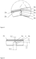
- a floor panel 1 is configured in the form of a rectangular board having at least two joints provided on opposite sides in the form of a receiving element 2 on one side and a connecting element 3 on the opposite side, the connecting element 3 and the receiving element 2 being configured such that, when a flooring is being installed, that is to say, when the floor panels 1 are being assembled, the connecting element 3 fits into the receiving element 2 in a form-locking manner, thus ensuring a tight joint between two adjacent floor panels 1.
- the receiving element 2 is configured as a recess 2a and the connecting element 3 is configured as a tongue 3a which fits into the recess 2a in a form-locking manner.
- the receiving element 2 is provided with an additional protrusion 2b and the connecting element 3 is provided with an indentation 3b, wherein upon the installation of the flooring, i.e. assembly of floor panels 1, the protrusion 2b fits into the indentation 3b.
- Said configuration of the receiving element 2 and the connecting element 3 also allows the joint to be easily opened if necessary, for example in the case where a single floor panel 1 needs to be replaced.
- the floor panel 1 is provided on its bottom face, that is the face which abuts the floor during installation, with at least one floor groove 4 in respective longitudinal and transverse directions.
- the floor panel 1 On each of the sides intended for a receiving element 2, the floor panel 1 is provided with at least one vertical groove 5 extending from the bottom surface of the floor panel 1 through the receiving element 2.
- the vertical groove 5 is formed in its upper portion, i.e. on the side facing the room when installed, in the form of a slot 5a, while it is formed in its bottom portion, i.e. on the side facing the ground when installed, in the form of an extension 5b, the transition from the slot 5a to the extension 5b being continuous.
- the continuous transition can be implemented in different ways, for example with straight lines or a curve or a combination of both.
- the ratio between the width W 1 of the slot 5a and the width W 2 of the extension 5b is between 1:1.1 and 1:10.
- the ratio between the height H 1 of the slot 5a and the height H 2 of the extension 5b is between 1:1 and 1:50.
- the width W 1 and the height H 1 of the slot 5a should be at least such to easily receive a cutting element of a tool for cutting the floor panel 1 and to allow adequate positioning of the tool for cutting the floor panel 1.
- This allows the floor panel 1 to be cut straight and square in both the horizontal and vertical directions, so that the individual floor panels 1 can be quickly and easily adjusted in length and width depending on the floor plan surface.
- the vertical groove 5 is preferably formed axially symmetrically with respect to the vertical axis.
- the floor panel 1 has a plurality of floor grooves 4 in the longitudinal and transverse directions, the floor grooves 4 preferably being equidistantly spaced.
- the floor panel 1 is provided with a plurality of vertical grooves 5, preferably arranged so that the extension 5b of each vertical groove 5 continues continuously into the corresponding floor groove 4.
- the width of the floor groove 4 is substantially identical to the width W 2 of the extension 5b.
- Floor panels 1 are preferably made of polymeric materials having a compressive strength in the range from 50 kPa to 800 kPa, which allow prefabrication by appropriate polymer processing techniques.
- the flooring assembly process includes laying the floor panels 1 on the floor and joining them by means of receiving elements 2 and connecting elements 3, so that a tight joint is made between the floor panels 1.
- the assembly process - installation method starts in a corner of a room, wherein the floor panels 1 are laid in rows, a first row being laid from one wall to the opposite wall, followed by a second row, and so on until the flooring is laid.
- the vertical grooves 5 are visible during the installation of the floor panels 1, it is also possible to precisely offset individual floor panels 1, if this is necessary due to the flooring layout.
- the floor assembly process comprises the following steps:
- the floor panel 1 is adequately trimmed before the installation and laid in accordance with the installation procedure described above.
Landscapes
- Engineering & Computer Science (AREA)
- Architecture (AREA)
- Civil Engineering (AREA)
- Structural Engineering (AREA)
- Floor Finish (AREA)
Applications Claiming Priority (1)
| Application Number | Priority Date | Filing Date | Title |
|---|---|---|---|
| SI202200145A SI26412A (sl) | 2022-08-29 | 2022-08-29 | Talni panel in postopek montaže talnih panelov |
Publications (2)
| Publication Number | Publication Date |
|---|---|
| EP4332322A2 true EP4332322A2 (de) | 2024-03-06 |
| EP4332322A3 EP4332322A3 (de) | 2024-03-13 |
Family
ID=88237888
Family Applications (1)
| Application Number | Title | Priority Date | Filing Date |
|---|---|---|---|
| EP23193654.3A Pending EP4332322A3 (de) | 2022-08-29 | 2023-08-28 | Bodenplatte und bodenplattenanordnungsverfahren |
Country Status (2)
| Country | Link |
|---|---|
| EP (1) | EP4332322A3 (de) |
| SI (1) | SI26412A (de) |
Citations (3)
| Publication number | Priority date | Publication date | Assignee | Title |
|---|---|---|---|---|
| EP1261785A1 (de) | 2000-03-07 | 2002-12-04 | E.F.P. Floor Products Fussböden GmbH | Mechanische verbindung von paneelen |
| EP1585867A1 (de) | 2003-01-24 | 2005-10-19 | John Redding | Unterwassersedimentverwaltung |
| EP2718516A1 (de) | 2011-06-06 | 2014-04-16 | Fritz Egger GmbH & Co. OG | Fussbodenpaneel mit einer einen sperrriegel aufweisenden seitenkante |
Family Cites Families (3)
| Publication number | Priority date | Publication date | Assignee | Title |
|---|---|---|---|---|
| DE29716028U1 (de) * | 1997-09-05 | 1997-10-30 | Akzenta Paneele + Profile GmbH, 56759 Kaisersesch | Laminatbelag, insbesondere für Fußböden |
| MY172014A (en) * | 2011-07-11 | 2019-11-12 | Ceraloc Innovation Ab | Mechanical locking system for floor panels |
| AU2013245653B2 (en) * | 2012-04-13 | 2016-02-11 | Armstrong World Industries, Inc. | Floating floor system, floor panel, and installation method for the same |
-
2022
- 2022-08-29 SI SI202200145A patent/SI26412A/sl active IP Right Grant
-
2023
- 2023-08-28 EP EP23193654.3A patent/EP4332322A3/de active Pending
Patent Citations (3)
| Publication number | Priority date | Publication date | Assignee | Title |
|---|---|---|---|---|
| EP1261785A1 (de) | 2000-03-07 | 2002-12-04 | E.F.P. Floor Products Fussböden GmbH | Mechanische verbindung von paneelen |
| EP1585867A1 (de) | 2003-01-24 | 2005-10-19 | John Redding | Unterwassersedimentverwaltung |
| EP2718516A1 (de) | 2011-06-06 | 2014-04-16 | Fritz Egger GmbH & Co. OG | Fussbodenpaneel mit einer einen sperrriegel aufweisenden seitenkante |
Also Published As
| Publication number | Publication date |
|---|---|
| SI26412A (sl) | 2024-03-29 |
| EP4332322A3 (de) | 2024-03-13 |
Similar Documents
| Publication | Publication Date | Title |
|---|---|---|
| US4896469A (en) | Prefabricated building panel assembly | |
| US10273689B2 (en) | Panel and method for fabricating, installing and utilizing a panel | |
| CN1254592C (zh) | 沿其纵侧面互相关联的薄的平面构件的接合配置 | |
| CN1151776A (zh) | 采用相互连接的泡沫面板的隔热式混凝土模壳 | |
| EP1907650B1 (de) | Abschlusskachel aus metall, herstellungsverfahren und verwandte abdeckung | |
| GB2291079A (en) | Insulated building blocks | |
| WO2017196522A1 (en) | Panel and method for fabricating, installing, and utilizing a panel | |
| JPWO2008149543A1 (ja) | せき板取付枠及び型枠工法 | |
| US10626606B2 (en) | Load transfer device | |
| KR101830354B1 (ko) | 벽체 시공용 블록 및 이를 이용한 건축용 벽체 | |
| KR100438756B1 (ko) | 건축물의 단열재 고정구 | |
| CA3219494A1 (en) | Interlockable wall reinforcement panel, wall reinforcement assembly and method for wall reinforcement | |
| JP7210470B2 (ja) | 特に水平建物構造を構成するための平坦な建物要素 | |
| US20120272596A1 (en) | Set of elements for constructing a wooden wall and method for using such elements | |
| EP2020471A1 (de) | Trockenbodensystem sowie ein Verfahren zur Erstellung eines Trockenbodensystems | |
| EP4182513B1 (de) | Mehrschichtiges wandelement zum aufbau von trockenwänden sowie trockenwand mit dem wandelement | |
| KR200258316Y1 (ko) | 건축물의 단열재 고정구 | |
| SI26412A (sl) | Talni panel in postopek montaže talnih panelov | |
| RU2220265C1 (ru) | Строительный стеновой блок | |
| JP7329212B2 (ja) | 板材施工具、板材施工構造、及び板材施工方法 | |
| JP3493997B2 (ja) | 床材の施工方法 | |
| JP2018115426A (ja) | 床材ユニットおよびその施工方法 | |
| SE511661C2 (sv) | Förfarande och profil vid sammansättning av byggblock samt byggblock att sammansättas enligt förfarandet | |
| JP2021161701A (ja) | 二重床構造 | |
| JP3303657B2 (ja) | 建築板の施工方法及び施工構造 |
Legal Events
| Date | Code | Title | Description |
|---|---|---|---|
| PUAI | Public reference made under article 153(3) epc to a published international application that has entered the european phase |
Free format text: ORIGINAL CODE: 0009012 |
|
| STAA | Information on the status of an ep patent application or granted ep patent |
Free format text: STATUS: THE APPLICATION HAS BEEN PUBLISHED |
|
| PUAL | Search report despatched |
Free format text: ORIGINAL CODE: 0009013 |
|
| AK | Designated contracting states |
Kind code of ref document: A2 Designated state(s): AL AT BE BG CH CY CZ DE DK EE ES FI FR GB GR HR HU IE IS IT LI LT LU LV MC ME MK MT NL NO PL PT RO RS SE SI SK SM TR |
|
| AK | Designated contracting states |
Kind code of ref document: A3 Designated state(s): AL AT BE BG CH CY CZ DE DK EE ES FI FR GB GR HR HU IE IS IT LI LT LU LV MC ME MK MT NL NO PL PT RO RS SE SI SK SM TR |
|
| RIC1 | Information provided on ipc code assigned before grant |
Ipc: E04F 15/02 20060101AFI20240206BHEP |
|
| STAA | Information on the status of an ep patent application or granted ep patent |
Free format text: STATUS: REQUEST FOR EXAMINATION WAS MADE |
|
| 17P | Request for examination filed |
Effective date: 20240906 |
|
| RBV | Designated contracting states (corrected) |
Designated state(s): AL AT BE BG CH CY CZ DE DK EE ES FI FR GB GR HR HU IE IS IT LI LT LU LV MC ME MK MT NL NO PL PT RO RS SE SI SK SM TR |