EP4332332B1 - Serrure électronique pour portes de véhicule de chargement - Google Patents
Serrure électronique pour portes de véhicule de chargement Download PDFInfo
- Publication number
- EP4332332B1 EP4332332B1 EP23382861.5A EP23382861A EP4332332B1 EP 4332332 B1 EP4332332 B1 EP 4332332B1 EP 23382861 A EP23382861 A EP 23382861A EP 4332332 B1 EP4332332 B1 EP 4332332B1
- Authority
- EP
- European Patent Office
- Prior art keywords
- locking
- electronic lock
- slider
- intermediate link
- door
- Prior art date
- Legal status (The legal status is an assumption and is not a legal conclusion. Google has not performed a legal analysis and makes no representation as to the accuracy of the status listed.)
- Active
Links
Images

Classifications
-
- E—FIXED CONSTRUCTIONS
- E05—LOCKS; KEYS; WINDOW OR DOOR FITTINGS; SAFES
- E05B—LOCKS; ACCESSORIES THEREFOR; HANDCUFFS
- E05B83/00—Vehicle locks specially adapted for particular types of wing or vehicle
- E05B83/02—Locks for railway freight-cars, freight containers or the like; Locks for the cargo compartments of commercial lorries, trucks or vans
-
- E—FIXED CONSTRUCTIONS
- E05—LOCKS; KEYS; WINDOW OR DOOR FITTINGS; SAFES
- E05B—LOCKS; ACCESSORIES THEREFOR; HANDCUFFS
- E05B47/00—Operating or controlling locks or other fastening devices by electric or magnetic means
- E05B47/06—Controlling mechanically-operated bolts by electro-magnetically-operated detents
- E05B47/0657—Controlling mechanically-operated bolts by electro-magnetically-operated detents by locking the handle, spindle, follower or the like
-
- E—FIXED CONSTRUCTIONS
- E05—LOCKS; KEYS; WINDOW OR DOOR FITTINGS; SAFES
- E05B—LOCKS; ACCESSORIES THEREFOR; HANDCUFFS
- E05B79/00—Mounting or connecting vehicle locks or parts thereof
- E05B79/10—Connections between movable lock parts
- E05B79/20—Connections between movable lock parts using flexible connections, e.g. Bowden cables
-
- E—FIXED CONSTRUCTIONS
- E05—LOCKS; KEYS; WINDOW OR DOOR FITTINGS; SAFES
- E05B—LOCKS; ACCESSORIES THEREFOR; HANDCUFFS
- E05B81/00—Power-actuated vehicle locks
- E05B81/02—Power-actuated vehicle locks characterised by the type of actuators used
- E05B81/04—Electrical
- E05B81/06—Electrical using rotary motors
-
- E—FIXED CONSTRUCTIONS
- E05—LOCKS; KEYS; WINDOW OR DOOR FITTINGS; SAFES
- E05B—LOCKS; ACCESSORIES THEREFOR; HANDCUFFS
- E05B81/00—Power-actuated vehicle locks
- E05B81/12—Power-actuated vehicle locks characterised by the function or purpose of the powered actuators
- E05B81/16—Power-actuated vehicle locks characterised by the function or purpose of the powered actuators operating on locking elements for locking or unlocking action
-
- E—FIXED CONSTRUCTIONS
- E05—LOCKS; KEYS; WINDOW OR DOOR FITTINGS; SAFES
- E05B—LOCKS; ACCESSORIES THEREFOR; HANDCUFFS
- E05B81/00—Power-actuated vehicle locks
- E05B81/54—Electrical circuits
- E05B81/90—Manual override in case of power failure
-
- E—FIXED CONSTRUCTIONS
- E05—LOCKS; KEYS; WINDOW OR DOOR FITTINGS; SAFES
- E05B—LOCKS; ACCESSORIES THEREFOR; HANDCUFFS
- E05B85/00—Details of vehicle locks not provided for in groups E05B77/00 - E05B83/00
- E05B85/20—Bolts or detents
- E05B85/22—Rectilinearly moving bolts
-
- E—FIXED CONSTRUCTIONS
- E05—LOCKS; KEYS; WINDOW OR DOOR FITTINGS; SAFES
- E05B—LOCKS; ACCESSORIES THEREFOR; HANDCUFFS
- E05B47/00—Operating or controlling locks or other fastening devices by electric or magnetic means
- E05B2047/0094—Mechanical aspects of remotely controlled locks
Definitions
- the present invention refers to the technical field of door closing systems, specifically to closing systems for truck and cargo vehicle doors, and more specifically to electronic lock systems that allow or block the opening of the door by means of a remotely actuated electronic system.
- the closing mechanisms usually incorporate locking and unlocking mechanisms of the slider to prevent or allow its linear movement when actuated by the lever, and thus prevent or allow the opening of the door.
- the most common locking and unlocking mechanisms consist of deadbolts connected to arms, levers, locks or hitches that lock or unlock the movement of the slider.
- deadbolts connected to arms, levers, locks or hitches that lock or unlock the movement of the slider.
- these mechanisms are uncomfortable and require the use of a key which must be inserted into the deadbolt for it to lock or open.
- An electronic lock is known from the document DE 10 2016 111252 A1 that is used for locking and unlocking locks on truck doors and cargo vehicles.
- An electronic lock for cargo vehicle doors is therefore desirable that allows a safe, comfortable and efficient opening and closing, avoiding the drawbacks of the existing systems in the prior art.
- the present invention relates to an electronic lock for cargo vehicle doors, having a base attachable to a cargo vehicle door such as a truck box door, an electronic system fixed to the base, remotely operable, with a motor, the electronic system being in charge of governing the closing and opening of the electronic lock.
- the electronic lock also has a handle on the base, a slider that engages the door to the frame thereof and that is actuated by means of the handle in a conventional way for opening the door by means of the linear displacement of said slider, and locking means arranged on the base connected to the electronic system and to the slider, to lock or allow the linear displacement of the slider, and thereby lock or allow the opening of the door by means of the actuation of the handle.
- the locking means are in turn formed by an actuating lever connected to the motor of the electronic system and actuated by it, and by an intermediate link connected to the slider and to the actuating lever and actuated by said actuating lever by rotation, said intermediate link having a locking stop.
- the locking means have a supplementary locking element that can rotate actuated by the intermediate link. By means of these elements the electronic lock is actuated between different positions.
- the locking stop of the intermediate link is separated from the complementary locking element, which allows the linear displacement of the slider, which will allow the door to be opened once the user actuates the handle.
- the simplest functioning of the electronic lock would consist of the following: starting from the locking position, in which the door is closed and the linear displacement of the slider is locked, if a user wishes to open the door, he will actuate the electronic system remotely, for example, by means of radio frequency (RF) or RFID, which will start the motor of the electronic system.
- This motor will actuate the actuating lever that is connected to the motor at one of its ends, and to the intermediate link at its other end.
- This movement of the actuating lever actuated by the motor will be transmitted by rotation of its second end to the intermediate link, which it will remove from its locking position by separating the locking stop from the complementary locking element, passing the electronic lock to the unlocking position.
- the complementary locking element can have elastic means such as springs or platforms, configured to rotate the complementary locking element and move from the opening position to the locking position of the electronic lock. In this way the locking element will rotate towards its position in the locking of the electronic lock aided by the elastic means during the closing of the electronic system.
- elastic means such as springs or platforms
- the electronic lock has a door sensor arranged on the base, in proximity to the frame, for detecting whether the door is open or closed and sending said information to the electronic system.
- the electronic system will detect that it has been closed and can activate the lock directly without the user having to actuate said electronic system.
- the electronic lock preferably has locking/unlocking sensors to detect protrusions of the intermediate link duly positioned on it, and thus be able to determine if the electronic lock is in a locking position or in an unlocking position and send said information to the electronic system, which will end the movements once the determined position is reached.
- the electronic lock of the present invention has the advantages of providing automatic locking of the doors of cargo vehicles, as well as unlocking by remote actuation means such as RF or RFID.
- the electronic lock object of the present invention has emergency opening means connected to the locking means, to be able to actuate the electronic lock to the unlocking position manually in case of failure of the electronic system, and to be able to open the door of the cargo vehicle despite any failure of the electronic system or lack of power, battery, etc...
- these emergency opening means are formed by a lock arranged on the door and a cable connected to said lock and to the intermediate link, to, by actuating the lock, with a key for example, move the intermediate link and thus separate its locking stop from the complementary locking element allowing the linear movement of the slider and consequently the opening of the door.
- This embodiment provides the advantage of facilitating an emergency manual opening in the event of electronic system failures or power failures, battery problems, etc.
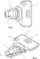
- the object of the present invention is an electronic lock 1 for doors of cargo vehicles, such as delivery vans, trucks, etc...
- the electronic lock 1 has a base 2 attachable to a door of a cargo vehicle, an electronic system 3 fixed to the base 2, which is remotely operable and is in charge of governing the closing and opening of the electronic lock 1.
- the electronic system 3 has a motor 7.
- the electronic lock 1 has a handle 4 on the base 2, a slider 5 that engages the door to the frame thereof and that is actuated in a conventional way by means of the handle 4 for opening the door by means of the linear displacement of said slider 5, and locking means 6 arranged on the base 2 that are connected to the electronic system 3 and to the slider 5, to lock or allow the linear displacement of said slider 5, and thereby lock or allow the opening of the door with the actuation of the handle 5.
- the locking means 6 are in turn formed by an actuating lever 8 that is connected to the motor 7 of the electronic system 3 and is actuated by it, and by an intermediate link 9 connected to the slider and to the actuating lever, which is actuated by said actuating lever 8 by rotating it.
- the intermediate link 9 has a locking stop 10 fundamental for the functioning of the electronic lock 1.
- the locking means 6 have a supplementary locking element 11 that can rotate actuated by the intermediate link 9 between different positions. By means of these elements the electronic lock 1 is actuated between different positions that are detailed below:
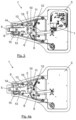
- Figure 4a shows the unlocking position.
- the locking stop 10 of the intermediate link 9 is in contact against the complementary locking element 11, which prevents the movement of the intermediate link 9, thus blocking the linear movement of the slider 5 in the opening direction, and thereby blocking the opening of the door even if the user actuates the handle 4.
- This is considered the default position of the electronic lock 1.
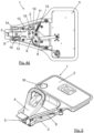
- Figure 4b shows the unlocking position.
- the locking stop 10 of the intermediate link 9 is separated from the complementary locking element 11, which allows the linear displacement of the slider 5 in the opening direction, which will allow the door to be opened once the user actuates the handle 4.
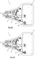
- Figure 4c shows the opening position. In the opening position, the functioning of the slider 5 by the handle 4 by means of the complete movement of the handle 4 has caused the opening of the door and the displacement of the intermediate link 9, and with this the rotation of the complementary locking element 11.
- figures 4a-4d show the different positions of the sequential functioning of the lock, which is described in detail below:
- the locking position shown in figure 4a in which the door is closed and the linear displacement of the slider 5 is locked (the contact of the locking stop 10 against the complementary locking element 11 prevents the linear displacement of the slider 5, as seen in figure 4a )
- the electronic system 3 remotely, for example, by means of RF or RFID, which starts the motor 7 of the electronic system 3.
- the motor 7 actuates the actuating lever 8, which, as seen in the figures, is connected to the motor 7 at one of its ends, and to the intermediate link 9 at its other end.
- this second end of the actuating lever 8 can rotate, and has a "trigger", which in its rotation connects with the end of the intermediate link 9 dragging it in said rotation.
- This rotation of the end of the intermediate link 9 separates the locking stop 10 from the complementary locking element 11, passing the electronic lock 1 to the unlocking position.
- the complementary locking element 11 can have elastic means 12 such as springs or platforms, to rotate the complementary locking element 11 from the position it had in the opening position to that of the locking position, and thus move from the opening position to the locking position of the electronic lock 1. In this way the locking element will rotate towards its previous position in the locking of the electronic lock 1 aided by the elastic means 12 during the closing of the electronic system.
- This passage from the opening position to the locking position with the return to the original position of the complementary locking element by means of the elastic means is represented in Figures 4c and 4d .
- the electronic lock 1 has a door sensor 14 arranged on the base 2, in proximity to the frame, for detecting whether the door is open or closed and sending said information to the electronic system 3.
- the electronic system 3 will detect that it has been closed and can activate the lock directly without the user having to actuate said electronic system 3 by remote means such as RF or RFID.
- the electronic system 3 can be programmed so that in case the electronic lock 1 is unlocked but the door is not opened, the system is automatically locked again after a few seconds. This is carried out if the door sensor 14 does not detect changes, which implies that the electronic lock 1 has been unlocked, but the door has not been opened.
- the electronic lock 1 preferably has locking/unlocking sensors 15 to detect protrusions 13 of the intermediate link 9 duly positioned on it, and thus be able to determine if the electronic lock 1 is in a locking position or in an unlocking position and send said information to the electronic system 3, which will end the movements once the determined position is reached.
- these locking/unlocking sensors 15 are arranged on the base 2, in the vicinity of the intermediate link 9, and depending on the position of said intermediate link 9, the projections 13 will approach one sensor 15 or another, determining the position of the electronic lock 1.
- the electronic lock 1 of the present invention has emergency opening means connected to the locking means 6, to be able to actuate the electronic lock 1 to the unlocking position manually in case of failure of the electronic system 3, and to be able to open the door of the cargo vehicle despite any failure of the electronic system 3 or lack of power, battery, etc.
- these emergency opening means are formed by a deadbolt 16 arranged on the door and a cable 17 connected to said deadbolt and to the intermediate link 9, to, by actuating the lock 16, with a key for example, be able to move the intermediate link 9 and thus separate the locking stop 10 from the complementary locking element 11 and allow the linear movement of the slider 5, and with it the opening of the door.
Landscapes
- Lock And Its Accessories (AREA)
Claims (6)
- Serrure électronique pour portes de véhicule de chargement, comprenant :- une base (2) pouvant être attachée à une porte d'un véhicule de chargement,- un système électronique (3) fixé à la base (2), actionnable à distance, configuré pour la fermeture et l'ouverture de la serrure électronique (1), comprenant un moteur (7),- une poignée (4) disposée dans la base (2),- un coulisseau (5) actionné par la poignée (4), configuré pour ouvrir la porte par le biais du mouvement linéaire dudit coulisseau (5), et- des moyens de verrouillage (6) disposés sur la base (2) et reliés au système électronique (3) et au coulisseau (5), configurés pour verrouiller et permettre le déplacement linéaire du coulisseau (5),dans laquelle les moyens de verrouillage (6) comprennent à leur tour- un levier d'actionnement (8) relié au moteur (7) et actionné par le moteur,- une liaison intermédiaire (9) reliée au coulisseau (5) et au levier d'actionnement (8) et actionnée par ledit levier d'actionnement (8) en rotation, la liaison intermédiaire (9) présentant une butée de verrouillage (10), et- un élément de verrouillage supplémentaire (11) configuré pour tourner actionné par la liaison intermédiaire (9),la serrure électronique (1) est configurée pour être actionnée entre- une position de verrouillage dans laquelle la butée de verrouillage (10) de la liaison intermédiaire (9) vient en contact avec l'élément de verrouillage supplémentaire (11) verrouillant le mouvement linéaire du coulisseau (5),- une position de déverrouillage dans laquelle la butée de verrouillage (10) de la liaison intermédiaire (9) est séparée de l'élément de verrouillage supplémentaire (11) permettant le mouvement linéaire du coulisseau (5), et- une position d'ouverture dans laquelle l'actionnement du coulisseau (5) par la poignée (4) a provoqué l'ouverture de la porte et le mouvement de la liaison intermédiaire (9) et, avec cela, la rotation de l'élément de verrouillage supplémentaire (11).
- Serrure électronique pour portes de véhicule de chargement selon la revendication 1, dans laquelle l'élément de verrouillage supplémentaire (11) comprend des moyens élastiques (12) configurés pour faire tourner l'élément de verrouillage supplémentaire (11) et se déplacer de la position d'ouverture vers la position de verrouillage de la serrure électronique (1).
- Serrure électronique pour portes de véhicules de chargement, selon l'une quelconque des revendications précédentes, comprenant un capteur de porte (14) configuré pour détecter si la porte est ouverte ou fermée et envoyer ladite information au système électronique (3).
- Serrure électronique pour portes de véhicules de chargement, selon l'une quelconque des revendications précédentes, comprenant des capteurs de verrouillage/déverrouillage (15) configurés pour détecter des saillies (13) de la liaison intermédiaire (9) et déterminer si la serrure électronique (1) se trouve dans la position de verrouillage ou dans la position de déverrouillage et envoyer ladite information au système électronique (3).
- Serrure électronique pour portes de véhicules de chargement, selon l'une quelconque des revendications précédentes, comprenant des moyens d'ouverture d'urgence reliés aux moyens de verrouillage (6) configurés pour actionner la serrure électronique (1) vers la position de déverrouillage manuellement en cas de défaillance du système électronique (3).
- Serrure électronique pour portes de véhicule de chargement selon la revendication 5, dans laquelle les moyens d'ouverture d'urgence comprennent- une serrure (16) disposé sur la porte et- un câble (17) relié à ladite serrure (16) et à la liaison intermédiaire (9), configuré pour déplacer ladite liaison intermédiaire (9) et séparer sa butée de verrouillage (10) à partir de l'élément de verrouillage supplémentaire (11) permettant le mouvement linéaire du coulisseau (5).
Applications Claiming Priority (1)
| Application Number | Priority Date | Filing Date | Title |
|---|---|---|---|
| ES202231421U ES1296816Y (es) | 2022-08-30 | 2022-08-30 | Cierre electrónico para puertas de vehículos de carga |
Publications (2)
| Publication Number | Publication Date |
|---|---|
| EP4332332A1 EP4332332A1 (fr) | 2024-03-06 |
| EP4332332B1 true EP4332332B1 (fr) | 2025-01-29 |
Family
ID=85078405
Family Applications (1)
| Application Number | Title | Priority Date | Filing Date |
|---|---|---|---|
| EP23382861.5A Active EP4332332B1 (fr) | 2022-08-30 | 2023-08-22 | Serrure électronique pour portes de véhicule de chargement |
Country Status (2)
| Country | Link |
|---|---|
| EP (1) | EP4332332B1 (fr) |
| ES (2) | ES1296816Y (fr) |
Families Citing this family (1)
| Publication number | Priority date | Publication date | Assignee | Title |
|---|---|---|---|---|
| ES3058193A1 (es) * | 2024-09-09 | 2026-03-09 | Mecanizados Rodriguez Fernandez S L | Sistema de cierre para puertas de cajas de vehículos de carga |
Family Cites Families (2)
| Publication number | Priority date | Publication date | Assignee | Title |
|---|---|---|---|---|
| DE102016111252A1 (de) * | 2016-06-20 | 2017-12-21 | Kiekert Ag | Verriegelungseinrichtung |
| ES1165183Y (es) * | 2016-09-08 | 2016-12-14 | Mecanizados Rodriguez Fernandez S L | Mecanismo de cierre para puertas de vehiculos de carga |
-
2022
- 2022-08-30 ES ES202231421U patent/ES1296816Y/es active Active
-
2023
- 2023-08-22 ES ES23382861T patent/ES3024462T3/es active Active
- 2023-08-22 EP EP23382861.5A patent/EP4332332B1/fr active Active
Also Published As
| Publication number | Publication date |
|---|---|
| ES1296816Y (es) | 2023-04-21 |
| EP4332332A1 (fr) | 2024-03-06 |
| ES1296816U (es) | 2023-02-01 |
| ES3024462T3 (en) | 2025-06-04 |
Similar Documents
| Publication | Publication Date | Title |
|---|---|---|
| US4342209A (en) | Central vehicle door-lock system | |
| CN108999501B (zh) | 具有动力释放机构和内侧把手释放机构的闭合闩锁组件 | |
| US11421454B2 (en) | Closure latch assembly with latch mechanism and outside release mechanism having reset device | |
| US10619385B2 (en) | Closure latch for a rear vehicle door having an emergency child lock release mechanism | |
| US5802894A (en) | Central locking system for an automotive vehicle with structurally identical door locks | |
| US10683682B2 (en) | Closure latch for vehicle door having double pull release mechanism driven by child lock actuator | |
| US5636536A (en) | Remotely operable security deadbolt lock device with anti-theft manually operable release | |
| US5715713A (en) | Door latch locking actuator assembly | |
| CN106246013B (zh) | 闩锁组件、机械锁芯释放机构及打开关闭闩锁的方法 | |
| US10513873B2 (en) | Closure latch for vehicle door | |
| EP1786999B1 (fr) | Dispositif a double verrouillage et deverouillage electrique | |
| US4440006A (en) | Antitheft central lock system for a motor vehicle | |
| CA1106024A (fr) | Systeme de securite sur vehicule | |
| US20100235057A1 (en) | Universal global latch system | |
| US20100244466A1 (en) | Closure Latch for Vehicle Door | |
| US8766769B2 (en) | Latch operating system and instruction method | |
| US20080217956A1 (en) | Motor Vehicle and Door Lock for a Door of a Motor Vehicle | |
| US6824177B1 (en) | Locking system for the door of a motor vehicle | |
| US20060049642A1 (en) | Lock for an opening on a motor vehicle, with a memory for unlocking locking | |
| JP2707036B2 (ja) | 自動車用ドアロックの操作装置 | |
| US5154457A (en) | Vehicular door lock device | |
| EP4332332B1 (fr) | Serrure électronique pour portes de véhicule de chargement | |
| EP0634547A2 (fr) | Système de verrouillage de porte pour véhicules | |
| US8044767B2 (en) | Smart entry system for vehicle | |
| KR100559568B1 (ko) | 자동차의 잼 방지형 도어 래치 |
Legal Events
| Date | Code | Title | Description |
|---|---|---|---|
| PUAI | Public reference made under article 153(3) epc to a published international application that has entered the european phase |
Free format text: ORIGINAL CODE: 0009012 |
|
| STAA | Information on the status of an ep patent application or granted ep patent |
Free format text: STATUS: THE APPLICATION HAS BEEN PUBLISHED |
|
| AK | Designated contracting states |
Kind code of ref document: A1 Designated state(s): AL AT BE BG CH CY CZ DE DK EE ES FI FR GB GR HR HU IE IS IT LI LT LU LV MC ME MK MT NL NO PL PT RO RS SE SI SK SM TR |
|
| STAA | Information on the status of an ep patent application or granted ep patent |
Free format text: STATUS: REQUEST FOR EXAMINATION WAS MADE |
|
| 17P | Request for examination filed |
Effective date: 20240313 |
|
| RBV | Designated contracting states (corrected) |
Designated state(s): AL AT BE BG CH CY CZ DE DK EE ES FI FR GB GR HR HU IE IS IT LI LT LU LV MC ME MK MT NL NO PL PT RO RS SE SI SK SM TR |
|
| RIN1 | Information on inventor provided before grant (corrected) |
Inventor name: PEREZ LAGO, MIGUEL |
|
| GRAP | Despatch of communication of intention to grant a patent |
Free format text: ORIGINAL CODE: EPIDOSNIGR1 |
|
| STAA | Information on the status of an ep patent application or granted ep patent |
Free format text: STATUS: GRANT OF PATENT IS INTENDED |
|
| INTG | Intention to grant announced |
Effective date: 20240613 |
|
| GRAJ | Information related to disapproval of communication of intention to grant by the applicant or resumption of examination proceedings by the epo deleted |
Free format text: ORIGINAL CODE: EPIDOSDIGR1 |
|
| STAA | Information on the status of an ep patent application or granted ep patent |
Free format text: STATUS: REQUEST FOR EXAMINATION WAS MADE |
|
| GRAP | Despatch of communication of intention to grant a patent |
Free format text: ORIGINAL CODE: EPIDOSNIGR1 |
|
| STAA | Information on the status of an ep patent application or granted ep patent |
Free format text: STATUS: GRANT OF PATENT IS INTENDED |
|
| INTC | Intention to grant announced (deleted) | ||
| INTG | Intention to grant announced |
Effective date: 20241009 |
|
| GRAS | Grant fee paid |
Free format text: ORIGINAL CODE: EPIDOSNIGR3 |
|
| GRAA | (expected) grant |
Free format text: ORIGINAL CODE: 0009210 |
|
| STAA | Information on the status of an ep patent application or granted ep patent |
Free format text: STATUS: THE PATENT HAS BEEN GRANTED |
|
| AK | Designated contracting states |
Kind code of ref document: B1 Designated state(s): AL AT BE BG CH CY CZ DE DK EE ES FI FR GB GR HR HU IE IS IT LI LT LU LV MC ME MK MT NL NO PL PT RO RS SE SI SK SM TR |
|
| REG | Reference to a national code |
Ref country code: GB Ref legal event code: FG4D |
|
| REG | Reference to a national code |
Ref country code: CH Ref legal event code: EP |
|
| REG | Reference to a national code |
Ref country code: DE Ref legal event code: R096 Ref document number: 602023001923 Country of ref document: DE |
|
| REG | Reference to a national code |
Ref country code: IE Ref legal event code: FG4D |
|
| REG | Reference to a national code |
Ref country code: NL Ref legal event code: MP Effective date: 20250129 Ref country code: ES Ref legal event code: FG2A Ref document number: 3024462 Country of ref document: ES Kind code of ref document: T3 Effective date: 20250604 |
|
| PG25 | Lapsed in a contracting state [announced via postgrant information from national office to epo] |
Ref country code: NL Free format text: LAPSE BECAUSE OF FAILURE TO SUBMIT A TRANSLATION OF THE DESCRIPTION OR TO PAY THE FEE WITHIN THE PRESCRIBED TIME-LIMIT Effective date: 20250129 |
|
| PG25 | Lapsed in a contracting state [announced via postgrant information from national office to epo] |
Ref country code: RS Free format text: LAPSE BECAUSE OF FAILURE TO SUBMIT A TRANSLATION OF THE DESCRIPTION OR TO PAY THE FEE WITHIN THE PRESCRIBED TIME-LIMIT Effective date: 20250429 |
|
| PG25 | Lapsed in a contracting state [announced via postgrant information from national office to epo] |
Ref country code: FI Free format text: LAPSE BECAUSE OF FAILURE TO SUBMIT A TRANSLATION OF THE DESCRIPTION OR TO PAY THE FEE WITHIN THE PRESCRIBED TIME-LIMIT Effective date: 20250129 |
|
| PG25 | Lapsed in a contracting state [announced via postgrant information from national office to epo] |
Ref country code: PL Free format text: LAPSE BECAUSE OF FAILURE TO SUBMIT A TRANSLATION OF THE DESCRIPTION OR TO PAY THE FEE WITHIN THE PRESCRIBED TIME-LIMIT Effective date: 20250129 |
|
| REG | Reference to a national code |
Ref country code: LT Ref legal event code: MG9D |
|
| PG25 | Lapsed in a contracting state [announced via postgrant information from national office to epo] |
Ref country code: IS Free format text: LAPSE BECAUSE OF FAILURE TO SUBMIT A TRANSLATION OF THE DESCRIPTION OR TO PAY THE FEE WITHIN THE PRESCRIBED TIME-LIMIT Effective date: 20250529 Ref country code: NO Free format text: LAPSE BECAUSE OF FAILURE TO SUBMIT A TRANSLATION OF THE DESCRIPTION OR TO PAY THE FEE WITHIN THE PRESCRIBED TIME-LIMIT Effective date: 20250429 |
|
| REG | Reference to a national code |
Ref country code: AT Ref legal event code: MK05 Ref document number: 1763583 Country of ref document: AT Kind code of ref document: T Effective date: 20250129 |
|
| PG25 | Lapsed in a contracting state [announced via postgrant information from national office to epo] |
Ref country code: HR Free format text: LAPSE BECAUSE OF FAILURE TO SUBMIT A TRANSLATION OF THE DESCRIPTION OR TO PAY THE FEE WITHIN THE PRESCRIBED TIME-LIMIT Effective date: 20250129 |
|
| PG25 | Lapsed in a contracting state [announced via postgrant information from national office to epo] |
Ref country code: LV Free format text: LAPSE BECAUSE OF FAILURE TO SUBMIT A TRANSLATION OF THE DESCRIPTION OR TO PAY THE FEE WITHIN THE PRESCRIBED TIME-LIMIT Effective date: 20250129 Ref country code: PT Free format text: LAPSE BECAUSE OF FAILURE TO SUBMIT A TRANSLATION OF THE DESCRIPTION OR TO PAY THE FEE WITHIN THE PRESCRIBED TIME-LIMIT Effective date: 20250529 |
|
| PG25 | Lapsed in a contracting state [announced via postgrant information from national office to epo] |
Ref country code: BG Free format text: LAPSE BECAUSE OF FAILURE TO SUBMIT A TRANSLATION OF THE DESCRIPTION OR TO PAY THE FEE WITHIN THE PRESCRIBED TIME-LIMIT Effective date: 20250129 Ref country code: GR Free format text: LAPSE BECAUSE OF FAILURE TO SUBMIT A TRANSLATION OF THE DESCRIPTION OR TO PAY THE FEE WITHIN THE PRESCRIBED TIME-LIMIT Effective date: 20250430 |
|
| PG25 | Lapsed in a contracting state [announced via postgrant information from national office to epo] |
Ref country code: AT Free format text: LAPSE BECAUSE OF FAILURE TO SUBMIT A TRANSLATION OF THE DESCRIPTION OR TO PAY THE FEE WITHIN THE PRESCRIBED TIME-LIMIT Effective date: 20250129 |
|
| PG25 | Lapsed in a contracting state [announced via postgrant information from national office to epo] |
Ref country code: SE Free format text: LAPSE BECAUSE OF FAILURE TO SUBMIT A TRANSLATION OF THE DESCRIPTION OR TO PAY THE FEE WITHIN THE PRESCRIBED TIME-LIMIT Effective date: 20250129 |
|
| PG25 | Lapsed in a contracting state [announced via postgrant information from national office to epo] |
Ref country code: SM Free format text: LAPSE BECAUSE OF FAILURE TO SUBMIT A TRANSLATION OF THE DESCRIPTION OR TO PAY THE FEE WITHIN THE PRESCRIBED TIME-LIMIT Effective date: 20250129 |
|
| PG25 | Lapsed in a contracting state [announced via postgrant information from national office to epo] |
Ref country code: DK Free format text: LAPSE BECAUSE OF FAILURE TO SUBMIT A TRANSLATION OF THE DESCRIPTION OR TO PAY THE FEE WITHIN THE PRESCRIBED TIME-LIMIT Effective date: 20250129 |
|
| PGFP | Annual fee paid to national office [announced via postgrant information from national office to epo] |
Ref country code: DE Payment date: 20250702 Year of fee payment: 3 |
|
| PG25 | Lapsed in a contracting state [announced via postgrant information from national office to epo] |
Ref country code: IT Free format text: LAPSE BECAUSE OF FAILURE TO SUBMIT A TRANSLATION OF THE DESCRIPTION OR TO PAY THE FEE WITHIN THE PRESCRIBED TIME-LIMIT Effective date: 20250129 |
|
| PGFP | Annual fee paid to national office [announced via postgrant information from national office to epo] |
Ref country code: FR Payment date: 20250825 Year of fee payment: 3 |
|
| PG25 | Lapsed in a contracting state [announced via postgrant information from national office to epo] |
Ref country code: EE Free format text: LAPSE BECAUSE OF FAILURE TO SUBMIT A TRANSLATION OF THE DESCRIPTION OR TO PAY THE FEE WITHIN THE PRESCRIBED TIME-LIMIT Effective date: 20250129 Ref country code: CZ Free format text: LAPSE BECAUSE OF FAILURE TO SUBMIT A TRANSLATION OF THE DESCRIPTION OR TO PAY THE FEE WITHIN THE PRESCRIBED TIME-LIMIT Effective date: 20250129 |
|
| PG25 | Lapsed in a contracting state [announced via postgrant information from national office to epo] |
Ref country code: RO Free format text: LAPSE BECAUSE OF FAILURE TO SUBMIT A TRANSLATION OF THE DESCRIPTION OR TO PAY THE FEE WITHIN THE PRESCRIBED TIME-LIMIT Effective date: 20250129 |
|
| PG25 | Lapsed in a contracting state [announced via postgrant information from national office to epo] |
Ref country code: SK Free format text: LAPSE BECAUSE OF FAILURE TO SUBMIT A TRANSLATION OF THE DESCRIPTION OR TO PAY THE FEE WITHIN THE PRESCRIBED TIME-LIMIT Effective date: 20250129 |
|
| REG | Reference to a national code |
Ref country code: DE Ref legal event code: R097 Ref document number: 602023001923 Country of ref document: DE |
|
| PLBE | No opposition filed within time limit |
Free format text: ORIGINAL CODE: 0009261 |
|
| STAA | Information on the status of an ep patent application or granted ep patent |
Free format text: STATUS: NO OPPOSITION FILED WITHIN TIME LIMIT |
|
| 26N | No opposition filed |
Effective date: 20251030 |
|
| PGFP | Annual fee paid to national office [announced via postgrant information from national office to epo] |
Ref country code: ES Payment date: 20251113 Year of fee payment: 3 |
|
| PG25 | Lapsed in a contracting state [announced via postgrant information from national office to epo] |
Ref country code: MC Free format text: LAPSE BECAUSE OF FAILURE TO SUBMIT A TRANSLATION OF THE DESCRIPTION OR TO PAY THE FEE WITHIN THE PRESCRIBED TIME-LIMIT Effective date: 20250129 |
|
| PG25 | Lapsed in a contracting state [announced via postgrant information from national office to epo] |
Ref country code: LU Free format text: LAPSE BECAUSE OF NON-PAYMENT OF DUE FEES Effective date: 20250822 |