EP4332352A1 - Antriebseinheit für ein flugzeug - Google Patents
Antriebseinheit für ein flugzeug Download PDFInfo
- Publication number
- EP4332352A1 EP4332352A1 EP23193700.4A EP23193700A EP4332352A1 EP 4332352 A1 EP4332352 A1 EP 4332352A1 EP 23193700 A EP23193700 A EP 23193700A EP 4332352 A1 EP4332352 A1 EP 4332352A1
- Authority
- EP
- European Patent Office
- Prior art keywords
- casing
- propulsion assembly
- cylinder
- turbine
- fixed
- Prior art date
- Legal status (The legal status is an assumption and is not a legal conclusion. Google has not performed a legal analysis and makes no representation as to the accuracy of the status listed.)
- Pending
Links
Images


Classifications
-
- F—MECHANICAL ENGINEERING; LIGHTING; HEATING; WEAPONS; BLASTING
- F02—COMBUSTION ENGINES; HOT-GAS OR COMBUSTION-PRODUCT ENGINE PLANTS
- F02C—GAS-TURBINE PLANTS; AIR INTAKES FOR JET-PROPULSION PLANTS; CONTROLLING FUEL SUPPLY IN AIR-BREATHING JET-PROPULSION PLANTS
- F02C7/00—Features, components parts, details or accessories, not provided for in, or of interest apart form groups F02C1/00 - F02C6/00; Air intakes for jet-propulsion plants
- F02C7/22—Fuel supply systems
- F02C7/222—Fuel flow conduits, e.g. manifolds
-
- B—PERFORMING OPERATIONS; TRANSPORTING
- B64—AIRCRAFT; AVIATION; COSMONAUTICS
- B64D—EQUIPMENT FOR FITTING IN OR TO AIRCRAFT; FLIGHT SUITS; PARACHUTES; ARRANGEMENT OR MOUNTING OF POWER PLANTS OR PROPULSION TRANSMISSIONS IN AIRCRAFT
- B64D27/00—Arrangement or mounting of power plants in aircraft; Aircraft characterised by the type or position of power plants
-
- B—PERFORMING OPERATIONS; TRANSPORTING
- B64—AIRCRAFT; AVIATION; COSMONAUTICS
- B64D—EQUIPMENT FOR FITTING IN OR TO AIRCRAFT; FLIGHT SUITS; PARACHUTES; ARRANGEMENT OR MOUNTING OF POWER PLANTS OR PROPULSION TRANSMISSIONS IN AIRCRAFT
- B64D45/00—Aircraft indicators or protectors not otherwise provided for
-
- F—MECHANICAL ENGINEERING; LIGHTING; HEATING; WEAPONS; BLASTING
- F01—MACHINES OR ENGINES IN GENERAL; ENGINE PLANTS IN GENERAL; STEAM ENGINES
- F01D—NON-POSITIVE DISPLACEMENT MACHINES OR ENGINES, e.g. STEAM TURBINES
- F01D21/00—Shutting-down of machines or engines, e.g. in emergency; Regulating, controlling, or safety means not otherwise provided for
- F01D21/04—Shutting-down of machines or engines, e.g. in emergency; Regulating, controlling, or safety means not otherwise provided for responsive to undesired position of rotor relative to stator or to breaking-off of a part of the rotor, e.g. indicating such position
- F01D21/045—Shutting-down of machines or engines, e.g. in emergency; Regulating, controlling, or safety means not otherwise provided for responsive to undesired position of rotor relative to stator or to breaking-off of a part of the rotor, e.g. indicating such position special arrangements in stators or in rotors dealing with breaking-off of part of rotor
-
- F—MECHANICAL ENGINEERING; LIGHTING; HEATING; WEAPONS; BLASTING
- F01—MACHINES OR ENGINES IN GENERAL; ENGINE PLANTS IN GENERAL; STEAM ENGINES
- F01D—NON-POSITIVE DISPLACEMENT MACHINES OR ENGINES, e.g. STEAM TURBINES
- F01D9/00—Stators
- F01D9/02—Nozzles; Nozzle boxes; Stator blades; Guide conduits, e.g. individual nozzles
- F01D9/026—Scrolls for radial machines or engines
-
- F—MECHANICAL ENGINEERING; LIGHTING; HEATING; WEAPONS; BLASTING
- F02—COMBUSTION ENGINES; HOT-GAS OR COMBUSTION-PRODUCT ENGINE PLANTS
- F02C—GAS-TURBINE PLANTS; AIR INTAKES FOR JET-PROPULSION PLANTS; CONTROLLING FUEL SUPPLY IN AIR-BREATHING JET-PROPULSION PLANTS
- F02C3/00—Gas-turbine plants characterised by the use of combustion products as the working fluid
- F02C3/20—Gas-turbine plants characterised by the use of combustion products as the working fluid using a special fuel, oxidant, or dilution fluid to generate the combustion products
- F02C3/22—Gas-turbine plants characterised by the use of combustion products as the working fluid using a special fuel, oxidant, or dilution fluid to generate the combustion products the fuel or oxidant being gaseous at standard temperature and pressure
-
- F—MECHANICAL ENGINEERING; LIGHTING; HEATING; WEAPONS; BLASTING
- F02—COMBUSTION ENGINES; HOT-GAS OR COMBUSTION-PRODUCT ENGINE PLANTS
- F02C—GAS-TURBINE PLANTS; AIR INTAKES FOR JET-PROPULSION PLANTS; CONTROLLING FUEL SUPPLY IN AIR-BREATHING JET-PROPULSION PLANTS
- F02C7/00—Features, components parts, details or accessories, not provided for in, or of interest apart form groups F02C1/00 - F02C6/00; Air intakes for jet-propulsion plants
- F02C7/22—Fuel supply systems
-
- B—PERFORMING OPERATIONS; TRANSPORTING
- B64—AIRCRAFT; AVIATION; COSMONAUTICS
- B64D—EQUIPMENT FOR FITTING IN OR TO AIRCRAFT; FLIGHT SUITS; PARACHUTES; ARRANGEMENT OR MOUNTING OF POWER PLANTS OR PROPULSION TRANSMISSIONS IN AIRCRAFT
- B64D37/00—Arrangements in connection with fuel supply for power plant
- B64D37/30—Fuel systems for specific fuels
-
- B—PERFORMING OPERATIONS; TRANSPORTING
- B64—AIRCRAFT; AVIATION; COSMONAUTICS
- B64D—EQUIPMENT FOR FITTING IN OR TO AIRCRAFT; FLIGHT SUITS; PARACHUTES; ARRANGEMENT OR MOUNTING OF POWER PLANTS OR PROPULSION TRANSMISSIONS IN AIRCRAFT
- B64D37/00—Arrangements in connection with fuel supply for power plant
- B64D37/32—Safety measures not otherwise provided for, e.g. preventing explosive conditions
-
- F—MECHANICAL ENGINEERING; LIGHTING; HEATING; WEAPONS; BLASTING
- F05—INDEXING SCHEMES RELATING TO ENGINES OR PUMPS IN VARIOUS SUBCLASSES OF CLASSES F01-F04
- F05D—INDEXING SCHEME FOR ASPECTS RELATING TO NON-POSITIVE-DISPLACEMENT MACHINES OR ENGINES, GAS-TURBINES OR JET-PROPULSION PLANTS
- F05D2240/00—Components
- F05D2240/10—Stators
- F05D2240/14—Casings or housings protecting or supporting assemblies within
-
- F—MECHANICAL ENGINEERING; LIGHTING; HEATING; WEAPONS; BLASTING
- F05—INDEXING SCHEMES RELATING TO ENGINES OR PUMPS IN VARIOUS SUBCLASSES OF CLASSES F01-F04
- F05D—INDEXING SCHEME FOR ASPECTS RELATING TO NON-POSITIVE-DISPLACEMENT MACHINES OR ENGINES, GAS-TURBINES OR JET-PROPULSION PLANTS
- F05D2240/00—Components
- F05D2240/10—Stators
- F05D2240/15—Heat shield
Definitions
- the present invention relates to a propulsion assembly for an aircraft, said propulsion assembly comprising a chassis fixed to a structure of a wing of the aircraft, a single-flow motor system such as a turboprop, fixed to the chassis, a pipeline of hydrogen which supplies the combustion chamber of the motorization system with said hydrogen and a protective cylinder fixed around the chassis between the dihydrogen pipe and the turbine of the motorization system.
- the invention also relates to an aircraft comprising at least one such propulsion assembly.
- an aircraft conventionally comprises at least one propulsion assembly comprising a single-flow motor system such as a turboprop.
- a motor system comprises a core which is enclosed in a casing and which comprises, among other things, from upstream to downstream, a compressor, a combustion chamber and a turbine.
- the motor system also includes a fan or a propeller driven in rotation by the core.
- the compressor and turbine each have blades that are attached to a rotating shaft.
- the propulsion assembly also comprises a chassis which is fixed to a structure of the wing of the aircraft and thus constitutes a mounting mast under the wing.
- dihydrogen as fuel in the combustion chamber.
- This dihydrogen is brought from a tank to the combustion chamber by a dihydrogen pipe which extends at least partly in the propulsion assembly. Due to the structure of the propulsion assembly and its position under the wing and on the front of the wing, the hydrogen pipe crosses the chassis coming from the wing and thus runs from the rear towards the ' forward to the combustion chamber.
- An object of the present invention is to propose a propulsion assembly which comprises protection means making it possible to protect a dihydrogen pipeline passing in the vicinity of the blades of the turbine of the single-flow engine system.
- a front end of the protection cylinder is positioned, perpendicular to the longitudinal axis, at least at the level of the blades of the turbine which are most forward, and the rear end of the protection cylinder is positioned, perpendicular to the longitudinal axis, at least at the level of the turbine blades which are furthest back.
- the protective cylinder protrudes in front of the turbine blades which are furthest forward and behind the turbine blades which are furthest back.
- the fixing means comprise a front fixing system arranged at a front part of the protective cylinder and two lateral fixing systems arranged on either side of a vertical median plane of the propulsion assembly
- the front mounting system comprises a front connecting rod fixed in an articulated manner by a first point of connection to the casing at the level of the median plane and by a second point of connection to the protection cylinder at the level of the median plane
- each lateral fixing system comprises a lateral connecting rod fixed in an articulated manner by a first connection point to the protection cylinder and by two second connection points to the casing.
- the fixing means comprise a front fixing system arranged at a front part of the protective cylinder and two lateral fixing systems arranged on either side of a vertical median plane of the propulsion assembly
- the front fixing system comprises a front connecting rod fixed in an articulated manner by a first point of connection to the chassis at the level of the median plane and by a second point of connection to the protective cylinder at the level of the median plane
- each system lateral fixing comprises a lateral connecting rod fixed in an articulated manner by a first point of connection to the chassis and by two second points of connection to the protection cylinder.
- the fixing means comprise an outer flange secured to the casing and an inner flange secured to the protection cylinder and arranged at a rear part of the protection cylinder, the inner flange rests on one side front of the outer flange and the fixing means comprise fixing elements which fix the two flanges against each other.
- the protective cylinder is made up of at least two hollow cylinder portions fixed to each other by securing systems.
- the protective cylinder consists of an upper half-cylinder and several lower half-cylinders fixed to the upper half-cylinder by securing systems and two neighboring lower half-cylinders are spaced from each other parallelly. to the longitudinal axis.
- the invention also proposes an aircraft comprising a wing, a dihydrogen tank and at least one propulsion assembly according to one of the preceding variants where the chassis is fixed to the wing and where the supply pipe is fluidly connected to the hydrogen tank. dihydrogen.
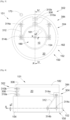
- FIG. 1 shows an aircraft 100 which has a fuselage 102 on either side of which is fixed a wing 104. Under each wing 104 is fixed at least one propulsion assembly 151 which comprises a nacelle 149 made up of covers 147 forming an aerodynamic exterior surface.
- Fig. 2 shows the propulsion assembly 151 which also includes a motorization system 150 which is represented schematically.
- the propulsion assembly 151 comprises a chassis 180 which ensures the attachment of the propulsion assembly 151 to a structure of the wing 104 and constitutes a mounting mast.
- the chassis 180 takes the form of a cage consisting, among other things, of beams attached to each other.
- the chassis 180 is fixed to the wing structure by fixing means known to those skilled in the art.
- the engine system 150 is a turboprop which comprises a core 152 which is enclosed in a casing 154.
- the casing 154 is housed inside the chassis 180 forming a cage and it is fixed there by any appropriate means known to those skilled in the art.
- the primary air flow 10 enters the core 152 to supply the combustion chamber 158 with oxygen.
- the casing 154 is thus open at the front to allow the introduction of the primary flow 10 into the core 152 and open at the rear to allow the exhaust of the gases resulting from combustion through a nozzle.
- the core 152 comprises, from upstream to downstream, a compressor 156, a combustion chamber 158 and a turbine 160.
- the compressor 156 and the turbine 160 are provided with blades 161 rotating around the longitudinal axis X.
- the primary flow 10 thus passes successively through the compressor 156 where it is compressed before being injected into the combustion chamber 158 where it is mixed with the fuel.
- the gases resulting from the combustion then pass through the turbine 160 and cause it to rotate.
- the turbine 160 then in turn drives the compressor 156 in rotation and the gases are then ejected at the rear.
- the motor system 150 comprises a propeller 162 which is at the front and driven in rotation by the turbine 160.
- the motor system 150 comprises also a gearbox 142 mounted between the turbine 160 and the propeller 162 which rotates around an axis of rotation 50 parallel to the longitudinal axis generally, the object of the invention is applied to a motorization system 150 with a primary flow 10 inside the core 152.
- the propulsion assembly 151 also includes a supply pipe 170 which makes it possible to convey dihydrogen as fuel to the combustion chamber 158 by being fluidly connected to a dihydrogen tank 172 of the aircraft 100.
- feed 170 thus winds from the rear of the nacelle 149 outside the casing 154 thus passing opposite and off the turbine 160 before plunging into the combustion chamber 158 through the casing 154.
- the propulsion assembly 151 includes a protective cylinder 182 which is fixed to the chassis 180 by fixing means 184 and it is arranged around the casing 154 and between the supply pipe 170 and the turbine 160.
- the axis of the protection cylinder 182 is generally coaxial with the longitudinal axis x.
- the protection cylinder 182 is fixed to the casing 154 by fixing means.
- the front end of the protection cylinder 182 is positioned, perpendicular to the longitudinal axis , perpendicular to the longitudinal axis
- a blade 161 of the turbine 160 can move radially relative to the longitudinal axis X, but there may be some dispersion and it can move forward or backward.
- the protective cylinder 182 protrudes in front of the blades 161 of the turbine 160 which are the most forward and behind the blades 161 of the turbine 160 which are the most rear.
- the supply pipe 170 extends preferentially in the upper part of said chassis 180 and therefore above the casing 154.
- the protective cylinder 182 is made for example of a titanium alloy with a high specific resistance such as the alloy known under the name Ti-6Al-4V and for example has a thickness of around 30 mm.
- Fig. 3 and the Fig. 4 show a first variant of the invention where the protective cylinder 182 is fixed to the casing 154 by fixing means 384.
- the fixing means 384 comprise a front fixing system 302 and two side fixing systems 304.
- the front fixing system 302 is arranged at a front part 306 of the protective cylinder 182 and the side fixing systems 304 are arranged on either side of the vertical median plane P (XZ) of the propulsion assembly 151 and at the rear of the front part 306.
- the front fixing system 302 comprises a front connecting rod 308 hingedly fixed by a first connection point 310a to the casing 154 at the median plane P and by a second connection point 310b to the protection cylinder 182 at the median plane P
- the first connection point 310a is below the second connection point 310b.
- the front connecting rod 308 is inscribed in a plane perpendicular to the longitudinal axis X.
- Each lateral fixing system 304 comprises a lateral connecting rod 312 fixed in an articulated manner by a first connection point 314a to the protective cylinder 182 and by two second connection points 314b-c to the casing 154 where the three connection points 314a-c of each lateral fixing system 304 are arranged in a plane parallel to the median plane P.
- the first connection point 314a is above the second connection points 314b-c.
- FIG. 5 and the Fig. 6 show a second variant of the invention where the protective cylinder 182 is fixed to the frame 180 by fixing means 584.
- the fixing means 584 comprise a front fixing system 502 and two side fixing systems 504.
- the front fixing system 502 is arranged at a front part 506 of the protective cylinder 182 and the side fixing systems 504 are arranged on either side of the vertical median plane P (XZ) of the propulsion assembly 151 and at the rear of the front part 506.
- the front fixing system 502 comprises a front connecting rod 508 hingedly fixed by a first connection point 510a to the chassis 180 at the median plane P and by a second connection point 510b to the protection cylinder 182 at the median plane P
- the first connection point 510a is above the second connection point 510b.
- the front connecting rod 508 is inscribed in a plane perpendicular to the longitudinal axis X.
- Each lateral fixing system 504 comprises a lateral connecting rod 512 fixed in an articulated manner by a first connection point 514a to the chassis 180 and by two second points of connection connection 514b-c to the protective cylinder 182 where the three connection points 514a-c of each lateral fixing system 504 are arranged in a plane parallel to the median plane P.
- the first connection point 514a is above the second connection points connection 514b-c.
- connection points 310a-b and 510a-b of the front fixing systems 302 and 502 are parallel to the longitudinal axis X and the axes of the connection points 314a-c and 514a-c lateral fixing systems 304 and 504 are parallel to the transverse axis Y.
- each connection point creates a ball joint connection, one embodiment of which is shown in section Fig. 10 .
- FIG. 10 shows a detail of each connection point 1100 between a first element 1102 and a second element 1104.
- the first element 1102 can be the frame 180, the casing 154 or the protective cylinder 182 and the second element 1104 is a connecting rod.
- the first element 1102 comprises a yoke with two branches 1106 between which is arranged a ball bearing 1108 secured to the second element 1104. Each branch is pierced with a bore in which an end sleeve 1110 is inserted. 1112 in the form of a hollow cylindrical barrel is, on the one hand slidably fitted into each of the end sleeves 1110, and on the other hand force-fitted into a bore made in the ball bearing 1108 in order to allow a pivoting of the ball bearing 1108 relative to the yoke around a connecting axis L.
- a screw 1114 is inserted into the hinge pin 1112 and a first flat locking washer 1116 is fitted onto the shank of the screw 1114 and inserted between the head of the screw 1114 and a sleeve end sleeve 1110, and on the other side of the yoke, a second flat locking washer 1118 is fitted onto the shank of the screw 1114 and inserted between the other end sleeve 1110 and a threaded end of the screw where a tightening nut 1120 is tightened to the desired torque on the threaded end of the screw 1114 to come against the second flat locking washer 1118 and maintain the washers 1116 and 1118 pressed against the end sleeves 1110.
- the assembly of the two elements to one another is finalized by the axial immobilization, along the connecting axis L, of the end sleeves 1110 and the ball bearing 1108.
- This immobilization is obtained because compaction between the tightening nut 1120 in contact with the second lock washer 1118 and the head of the screw 1114 in contact with the first lock washer 1116.
- FIG. 7 shows a third variant of the invention where the protective cylinder 182 is fixed to the frame 180 by fixing means 784.
- the fixing means 784 comprise an outer flange 702 and an inner flange 704.
- the flanges 702 and 704 are arranged at a rear part 706 of the protection cylinder 182. But according to another embodiment of the invention not shown, they are arranged at a front part of the protection cylinder 182.
- a pair of flange 702,704 is arranged at a rear part 706 of the protection cylinder, and another pair of flange 702,704 is arranged at a front part of the protection cylinder. protection 182.
- the outer flange 702 is secured to the casing 154 and the inner flange 704 is secured to the protection cylinder 182.
- the protective cylinder 182 is around the casing 154 and the inner flange 704 rests on a front face of the outer flange 702.
- the fixing means 784 comprise fixing elements 708 which fix the two flanges 702 and 704 one by one. against the other.
- the fixing elements 708 are for example bolts.
- the protective cylinder 182 is made up of a single element but it can be made up of several elements fixed to each other.
- the protective cylinder 182 is made up of at least two hollow cylinder portions 802a-b fixed to each other by securing systems 804.
- the securing systems 804 are here longitudinal ribs fixed by bolts. This embodiment can be applied to all the variants described above.
- the fixing means 184 are not shown, but they can take the form of those described above.
- the protective cylinder 182 As shown in Fig. 9 , to lighten the protective cylinder 182, it is made up of an upper half-cylinder 902 and several lower half-cylinders 904a-c, here three in number, which are all coaxial.
- the upper half-cylinder 902 is full and complete over its entire length to serve as protection for the supply pipe 170 which is above.
- the lower half-cylinders 904a-c extend parallel to the longitudinal direction longitudinal ribs fixed by bolts and there are empty spaces between two consecutive lower half-cylinders 904a-c. Two neighboring lower half-cylinders 904a-c are spaced apart from each other parallel to the longitudinal axis X.
Landscapes
- Engineering & Computer Science (AREA)
- Chemical & Material Sciences (AREA)
- Combustion & Propulsion (AREA)
- Mechanical Engineering (AREA)
- General Engineering & Computer Science (AREA)
- Aviation & Aerospace Engineering (AREA)
- General Details Of Gearings (AREA)
- Turbine Rotor Nozzle Sealing (AREA)
- Mutual Connection Of Rods And Tubes (AREA)
- Structures Of Non-Positive Displacement Pumps (AREA)
Applications Claiming Priority (1)
| Application Number | Priority Date | Filing Date | Title |
|---|---|---|---|
| FR2208674A FR3139118A1 (fr) | 2022-08-30 | 2022-08-30 | Ensemble propulsif pour aéronef |
Publications (1)
| Publication Number | Publication Date |
|---|---|
| EP4332352A1 true EP4332352A1 (de) | 2024-03-06 |
Family
ID=83996138
Family Applications (1)
| Application Number | Title | Priority Date | Filing Date |
|---|---|---|---|
| EP23193700.4A Pending EP4332352A1 (de) | 2022-08-30 | 2023-08-28 | Antriebseinheit für ein flugzeug |
Country Status (4)
| Country | Link |
|---|---|
| US (1) | US12398677B2 (de) |
| EP (1) | EP4332352A1 (de) |
| CN (1) | CN117627786A (de) |
| FR (1) | FR3139118A1 (de) |
Citations (8)
| Publication number | Priority date | Publication date | Assignee | Title |
|---|---|---|---|---|
| DE2413507A1 (de) | 1974-03-20 | 1975-10-02 | Motoren Turbinen Union | Gasturbine fuer kryogenen kraftstoff |
| GB1453873A (en) | 1973-02-02 | 1976-10-27 | Norton Co | Protective guard mounted on a turbine engine for aircraft |
| US20050025615A1 (en) | 2003-07-30 | 2005-02-03 | The Boeing Company | High energy containment device and turbine with same |
| US20080073460A1 (en) * | 2006-05-06 | 2008-03-27 | Beardsley Peter K | Aeroengine mount |
| US20120082541A1 (en) * | 2010-09-30 | 2012-04-05 | Enzo Macchia | Gas turbine engine casing |
| US20170198604A1 (en) | 2016-01-12 | 2017-07-13 | Pratt & Whitney Canada Corp. | Cooled containment case using internal plenum |
| US20180283204A1 (en) * | 2017-03-31 | 2018-10-04 | The Boeing Company | Gas turbine engine fan blade containment systems |
| US20180320633A1 (en) * | 2017-02-22 | 2018-11-08 | General Electric Company | Aircraft and Direct Drive Engine Under Wing Installation |
Family Cites Families (2)
| Publication number | Priority date | Publication date | Assignee | Title |
|---|---|---|---|---|
| FR2964145B1 (fr) * | 2010-08-26 | 2018-06-15 | Safran Helicopter Engines | Procede d'accrochage de blindage sur carter de turbine et ensemble d'accrochage pour sa mise en oeuvre |
| US11946419B2 (en) * | 2022-02-23 | 2024-04-02 | General Electric Company | Methods and apparatus to produce hydrogen gas turbine propulsion |
-
2022
- 2022-08-30 FR FR2208674A patent/FR3139118A1/fr not_active Ceased
-
2023
- 2023-08-28 US US18/456,587 patent/US12398677B2/en active Active
- 2023-08-28 EP EP23193700.4A patent/EP4332352A1/de active Pending
- 2023-08-30 CN CN202311105649.5A patent/CN117627786A/zh active Pending
Patent Citations (8)
| Publication number | Priority date | Publication date | Assignee | Title |
|---|---|---|---|---|
| GB1453873A (en) | 1973-02-02 | 1976-10-27 | Norton Co | Protective guard mounted on a turbine engine for aircraft |
| DE2413507A1 (de) | 1974-03-20 | 1975-10-02 | Motoren Turbinen Union | Gasturbine fuer kryogenen kraftstoff |
| US20050025615A1 (en) | 2003-07-30 | 2005-02-03 | The Boeing Company | High energy containment device and turbine with same |
| US20080073460A1 (en) * | 2006-05-06 | 2008-03-27 | Beardsley Peter K | Aeroengine mount |
| US20120082541A1 (en) * | 2010-09-30 | 2012-04-05 | Enzo Macchia | Gas turbine engine casing |
| US20170198604A1 (en) | 2016-01-12 | 2017-07-13 | Pratt & Whitney Canada Corp. | Cooled containment case using internal plenum |
| US20180320633A1 (en) * | 2017-02-22 | 2018-11-08 | General Electric Company | Aircraft and Direct Drive Engine Under Wing Installation |
| US20180283204A1 (en) * | 2017-03-31 | 2018-10-04 | The Boeing Company | Gas turbine engine fan blade containment systems |
Also Published As
| Publication number | Publication date |
|---|---|
| US20240067355A1 (en) | 2024-02-29 |
| US12398677B2 (en) | 2025-08-26 |
| CN117627786A (zh) | 2024-03-01 |
| FR3139118A1 (fr) | 2024-03-01 |
Similar Documents
| Publication | Publication Date | Title |
|---|---|---|
| EP2244943B1 (de) | Flugzeugtriebwerkanordnung mit einer ringförmigen lastentransferstruktur um das zentralgehäuse eines turboluftstrahltriebwerks | |
| EP3377732B1 (de) | Vorderer teil einer turbomaschine | |
| EP1883578A2 (de) | Triebwerkpylonaufhängung für ein flugzeug | |
| WO2006097484A1 (fr) | Attache moteur d'un systeme de montage interpose entre un mat d'accrochage et un moteur d'aeronef | |
| CA2743009C (fr) | Entree d'air d'un moteur d'avion a helices propulsives non carenees | |
| FR2925016A1 (fr) | Suspension d'un turboreacteur a un aeronef | |
| EP4355983B1 (de) | Nicht ummantelte leitschaufelanordnung einer turbomaschine, modul einer turbomaschine und turbomaschine eines flugzeugs | |
| CA2811147A1 (fr) | Dispositif de liaison d'un cadre avant d'inverseur de poussee a un carter de soufflante, et nacelle incorporant un tel dispositif | |
| FR2963320A1 (fr) | Attache moteur avant amelioree pour moteur d'aeronef | |
| EP4331993B1 (de) | Antriebseinheit für ein flugzeug | |
| FR3043648A1 (fr) | Voilure propulsive d'un aeronef | |
| EP4332352A1 (de) | Antriebseinheit für ein flugzeug | |
| FR3079212A1 (fr) | Ensemble de motorisation pour un aeronef | |
| FR2961257A1 (fr) | Procede de montage d'une vanne de decharge dans un turboreacteur d'aeronef, vanne de decharge, et turboreacteur comprenant une telle vanne | |
| FR2933127A1 (fr) | Dispositif de prelevement d'air de refroidissement dans une turbomachine | |
| FR2937679A1 (fr) | Dispositif de prelevement d'air de refroidissement dans une turbomachine | |
| EP3728039B1 (de) | Aufhängevorrichtung | |
| EP0582522B1 (de) | Triebwerkaufhängung an Luftfahrzeugstruktur | |
| EP4363313B1 (de) | Propeller für eine turbomaschine eines luftfahrzeuges mit einer verstellbaren schaufel und einer gegengewichtsvorrichtung mit zahnradgetriebe | |
| FR2909973A1 (fr) | Mat d'accrochage de turboreacteur pour aeronef a structure arriere de largeur transversale reduite | |
| EP4345010B1 (de) | Antriebseinheit für ein flugzeug | |
| FR2952704A1 (fr) | Guidage rotulant d'une bougie d'allumage dans une chambre de combustion d'une turbomachine | |
| EP4001120B1 (de) | Baugruppe für ein luftfahrzeug mit einem mast und einer gondel, die eine haube umfasst, die mit spann- und zentriersystemen ausgestattet ist | |
| EP4345009B1 (de) | Antriebseinheit für ein flugzeug | |
| EP4458682B1 (de) | Flugzeug mit mindestens einer flüssigkeitsversorgungsschaltung mit mindestens einem selbstschliessenden verschluss |
Legal Events
| Date | Code | Title | Description |
|---|---|---|---|
| PUAI | Public reference made under article 153(3) epc to a published international application that has entered the european phase |
Free format text: ORIGINAL CODE: 0009012 |
|
| STAA | Information on the status of an ep patent application or granted ep patent |
Free format text: STATUS: THE APPLICATION HAS BEEN PUBLISHED |
|
| AK | Designated contracting states |
Kind code of ref document: A1 Designated state(s): AL AT BE BG CH CY CZ DE DK EE ES FI FR GB GR HR HU IE IS IT LI LT LU LV MC ME MK MT NL NO PL PT RO RS SE SI SK SM TR |
|
| STAA | Information on the status of an ep patent application or granted ep patent |
Free format text: STATUS: REQUEST FOR EXAMINATION WAS MADE |
|
| 17P | Request for examination filed |
Effective date: 20240903 |
|
| RBV | Designated contracting states (corrected) |
Designated state(s): AL AT BE BG CH CY CZ DE DK EE ES FI FR GB GR HR HU IE IS IT LI LT LU LV MC ME MK MT NL NO PL PT RO RS SE SI SK SM TR |
|
| STAA | Information on the status of an ep patent application or granted ep patent |
Free format text: STATUS: EXAMINATION IS IN PROGRESS |
|
| 17Q | First examination report despatched |
Effective date: 20250514 |
|
| GRAP | Despatch of communication of intention to grant a patent |
Free format text: ORIGINAL CODE: EPIDOSNIGR1 |
|
| STAA | Information on the status of an ep patent application or granted ep patent |
Free format text: STATUS: GRANT OF PATENT IS INTENDED |
|
| RIC1 | Information provided on ipc code assigned before grant |
Ipc: F01D 21/04 20060101AFI20260121BHEP Ipc: B64D 27/00 20060101ALI20260121BHEP Ipc: B64D 45/00 20060101ALI20260121BHEP Ipc: B64D 37/32 20060101ALI20260121BHEP Ipc: F02C 3/22 20060101ALN20260121BHEP Ipc: B64D 37/30 20060101ALN20260121BHEP |
|
| INTG | Intention to grant announced |
Effective date: 20260130 |
|
| RIC1 | Information provided on ipc code assigned before grant |
Ipc: F01D 21/04 20060101AFI20260123BHEP Ipc: B64D 27/00 20060101ALI20260123BHEP Ipc: B64D 45/00 20060101ALI20260123BHEP Ipc: B64D 37/32 20060101ALI20260123BHEP Ipc: F02C 3/22 20060101ALN20260123BHEP Ipc: B64D 37/30 20060101ALN20260123BHEP |