EP4332361A1 - Modification de force proportionnelle de tiroir passif pour la commande d'un circuit simplex d'injecteurs de carburant - Google Patents
Modification de force proportionnelle de tiroir passif pour la commande d'un circuit simplex d'injecteurs de carburant Download PDFInfo
- Publication number
- EP4332361A1 EP4332361A1 EP23193571.9A EP23193571A EP4332361A1 EP 4332361 A1 EP4332361 A1 EP 4332361A1 EP 23193571 A EP23193571 A EP 23193571A EP 4332361 A1 EP4332361 A1 EP 4332361A1
- Authority
- EP
- European Patent Office
- Prior art keywords
- valve
- injector
- recited
- inlet
- fluid communication
- Prior art date
- Legal status (The legal status is an assumption and is not a legal conclusion. Google has not performed a legal analysis and makes no representation as to the accuracy of the status listed.)
- Granted
Links
Images


Classifications
-
- F—MECHANICAL ENGINEERING; LIGHTING; HEATING; WEAPONS; BLASTING
- F02—COMBUSTION ENGINES; HOT-GAS OR COMBUSTION-PRODUCT ENGINE PLANTS
- F02C—GAS-TURBINE PLANTS; AIR INTAKES FOR JET-PROPULSION PLANTS; CONTROLLING FUEL SUPPLY IN AIR-BREATHING JET-PROPULSION PLANTS
- F02C7/00—Features, components parts, details or accessories, not provided for in, or of interest apart form groups F02C1/00 - F02C6/00; Air intakes for jet-propulsion plants
- F02C7/22—Fuel supply systems
- F02C7/232—Fuel valves; Draining valves or systems
-
- F—MECHANICAL ENGINEERING; LIGHTING; HEATING; WEAPONS; BLASTING
- F02—COMBUSTION ENGINES; HOT-GAS OR COMBUSTION-PRODUCT ENGINE PLANTS
- F02C—GAS-TURBINE PLANTS; AIR INTAKES FOR JET-PROPULSION PLANTS; CONTROLLING FUEL SUPPLY IN AIR-BREATHING JET-PROPULSION PLANTS
- F02C7/00—Features, components parts, details or accessories, not provided for in, or of interest apart form groups F02C1/00 - F02C6/00; Air intakes for jet-propulsion plants
- F02C7/22—Fuel supply systems
- F02C7/228—Dividing fuel between various burners
-
- F—MECHANICAL ENGINEERING; LIGHTING; HEATING; WEAPONS; BLASTING
- F02—COMBUSTION ENGINES; HOT-GAS OR COMBUSTION-PRODUCT ENGINE PLANTS
- F02C—GAS-TURBINE PLANTS; AIR INTAKES FOR JET-PROPULSION PLANTS; CONTROLLING FUEL SUPPLY IN AIR-BREATHING JET-PROPULSION PLANTS
- F02C7/00—Features, components parts, details or accessories, not provided for in, or of interest apart form groups F02C1/00 - F02C6/00; Air intakes for jet-propulsion plants
- F02C7/22—Fuel supply systems
- F02C7/222—Fuel flow conduits, e.g. manifolds
-
- F—MECHANICAL ENGINEERING; LIGHTING; HEATING; WEAPONS; BLASTING
- F02—COMBUSTION ENGINES; HOT-GAS OR COMBUSTION-PRODUCT ENGINE PLANTS
- F02C—GAS-TURBINE PLANTS; AIR INTAKES FOR JET-PROPULSION PLANTS; CONTROLLING FUEL SUPPLY IN AIR-BREATHING JET-PROPULSION PLANTS
- F02C9/00—Controlling gas-turbine plants; Controlling fuel supply in air- breathing jet-propulsion plants
- F02C9/26—Control of fuel supply
- F02C9/263—Control of fuel supply by means of fuel metering valves
-
- F—MECHANICAL ENGINEERING; LIGHTING; HEATING; WEAPONS; BLASTING
- F23—COMBUSTION APPARATUS; COMBUSTION PROCESSES
- F23R—GENERATING COMBUSTION PRODUCTS OF HIGH PRESSURE OR HIGH VELOCITY, e.g. GAS-TURBINE COMBUSTION CHAMBERS
- F23R3/00—Continuous combustion chambers using liquid or gaseous fuel
- F23R3/28—Continuous combustion chambers using liquid or gaseous fuel characterised by the fuel supply
- F23R3/34—Feeding into different combustion zones
- F23R3/346—Feeding into different combustion zones for staged combustion
-
- F—MECHANICAL ENGINEERING; LIGHTING; HEATING; WEAPONS; BLASTING
- F05—INDEXING SCHEMES RELATING TO ENGINES OR PUMPS IN VARIOUS SUBCLASSES OF CLASSES F01-F04
- F05D—INDEXING SCHEME FOR ASPECTS RELATING TO NON-POSITIVE-DISPLACEMENT MACHINES OR ENGINES, GAS-TURBINES OR JET-PROPULSION PLANTS
- F05D2260/00—Function
- F05D2260/60—Fluid transfer
- F05D2260/606—Bypassing the fluid
-
- F—MECHANICAL ENGINEERING; LIGHTING; HEATING; WEAPONS; BLASTING
- F05—INDEXING SCHEMES RELATING TO ENGINES OR PUMPS IN VARIOUS SUBCLASSES OF CLASSES F01-F04
- F05D—INDEXING SCHEME FOR ASPECTS RELATING TO NON-POSITIVE-DISPLACEMENT MACHINES OR ENGINES, GAS-TURBINES OR JET-PROPULSION PLANTS
- F05D2260/00—Function
- F05D2260/96—Preventing, counteracting or reducing vibration or noise
- F05D2260/964—Preventing, counteracting or reducing vibration or noise counteracting thermoacoustic noise
-
- F—MECHANICAL ENGINEERING; LIGHTING; HEATING; WEAPONS; BLASTING
- F05—INDEXING SCHEMES RELATING TO ENGINES OR PUMPS IN VARIOUS SUBCLASSES OF CLASSES F01-F04
- F05D—INDEXING SCHEME FOR ASPECTS RELATING TO NON-POSITIVE-DISPLACEMENT MACHINES OR ENGINES, GAS-TURBINES OR JET-PROPULSION PLANTS
- F05D2270/00—Control
- F05D2270/01—Purpose of the control system
- F05D2270/14—Purpose of the control system to control thermoacoustic behaviour in the combustion chambers
-
- F—MECHANICAL ENGINEERING; LIGHTING; HEATING; WEAPONS; BLASTING
- F05—INDEXING SCHEMES RELATING TO ENGINES OR PUMPS IN VARIOUS SUBCLASSES OF CLASSES F01-F04
- F05D—INDEXING SCHEME FOR ASPECTS RELATING TO NON-POSITIVE-DISPLACEMENT MACHINES OR ENGINES, GAS-TURBINES OR JET-PROPULSION PLANTS
- F05D2270/00—Control
- F05D2270/30—Control parameters, e.g. input parameters
- F05D2270/31—Fuel schedule for stage combustors
-
- F—MECHANICAL ENGINEERING; LIGHTING; HEATING; WEAPONS; BLASTING
- F05—INDEXING SCHEMES RELATING TO ENGINES OR PUMPS IN VARIOUS SUBCLASSES OF CLASSES F01-F04
- F05D—INDEXING SCHEME FOR ASPECTS RELATING TO NON-POSITIVE-DISPLACEMENT MACHINES OR ENGINES, GAS-TURBINES OR JET-PROPULSION PLANTS
- F05D2270/00—Control
- F05D2270/40—Type of control system
- F05D2270/42—Type of control system passive or reactive, e.g. using large wind vanes
Definitions
- the present disclosure relates to injectors and nozzles, and more particularly to fuel injection such as in gas turbine engines.
- adjustments to fuel scheduling may be directed, in an attempt to decouple the heat release and noise; however, these attempts require additional flow dividing hardware and fuel manifolds adding significant cost, weight, and power requirements.
- a system includes an injector including a scheduling valve assembly and a nozzle in fluid communication with the valve assembly.
- the scheduling valve assembly is configured for regulation of flow from an inlet of the injector to the nozzle.
- the injector includes one fluid circuit between the inlet of the injector and a respective outlet of the nozzle.
- a solenoid valve is connected in fluid communication with the scheduling valve assembly. The solenoid valve is configured to adjust position of a hydromechanical valve spool of the valve assembly.
- the separate valve can be a discrete open/closed valve. It is also contemplated that the separate valve can be a proportional valve with intermediate conditions between fully open and fully closed.
- the proportional valve can include a proportional solenoid, stepper motor, or a torque motor based servo valve with flapper and nozzle.
- the valve spool can be biased to a closed position by one or more biasing members of the scheduling valve assembly.
- the valve spool can be configured to regulate flow from the inlet of the injector to the fluid circuit.
- the valve spool can include a scheduling surface configured to vary flow area through the fluid circuit based on position of the valve spool within the scheduling valve assembly.
- the solenoid valve can have an inlet, an outlet, and a solenoid valve member configured to control flow through the solenoid valve from the inlet to the outlet based on electrical power applied to an armature of the solenoid valve.
- the inlet of the solenoid valve can be connected in fluid communication with the inlet of the injector.
- the outlet of the solenoid valve can be connected in fluid communication with the fluid circuit.
- the outlet of the solenoid valve can connect to the fluid circuit at a position in the fluid circuit that is downstream of the valve assembly.
- the valve spool can include a piston with an orifice therethrough, wherein the piston and orifice are configured to regulate pressure differential across the valve assembly.
- the orifice can be in fluid communication in series between the inlet of the injector and the inlet of the solenoid valve.
- the solenoid valve can be a three-way valve including a first port in fluid communication with the fluid circuit downstream of the inlet of the injector.
- a second port can be in fluid communication with the inlet of the injector.
- a third port can be in fluid communication with the valve spool for selectively adjusting position of the valve spool in the valve assembly based on pressure from the inlet of the injector or pressure from the fluid circuit.
- the first port of the solenoid valve can be connected in fluid communication with a portion of the fluid circuit downstream of the valve spool.
- the third port can be connected in fluid communication with a back piston of the valve spool.
- the injector can be a first injector in a plurality of injectors each connected in fluid communication with a single manifold for supplying fuel to each injector in the plurality of injectors including the fluid circuit of the first injector.
- a first sub-set of the plurality of injectors can be passive, duplex nozzles each having a primary circuit for use independent of the fluid circuit of the first injector, and a secondary circuit configured to issue fuel together with the fluid circuit of the first injector.
- the first injector can be a first injector in a second sub-set of the plurality of injectors. Each injector in the second sub-set can be as described above including a respective separate valve as described above connected thereto.
- a controller can be electrically connected to the solenoid valves for individual control thereof.
- a controller can be electrically connected to the solenoid valves for ganged control thereof.
- the first sub-set of injectors can be grouped circumferentially offset from the second sub-set of injectors.
- the separate valve can be a binary valve, a modulating valve, a motorized valve, or any other suitable type of valve, e.g. separate from the scheduling valve.
- the respective separate valve can be a proportional valve with intermediate conditions between fully open and fully closed.
- Each of the injectors in the plurality of fuel injectors can include a mass flow sensor operatively connected to the controller to provide mass flow feedback to the controller. Loss of electrical power to the separate valve can cause the valve spool to return to a position determined by mechanical components and regulates fuel flow as per a scheduling surface.
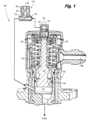
- Fig. 1 a partial view of an embodiment of a system in accordance with the disclosure is shown in Fig. 1 and is designated generally by reference character 100.
- Other embodiments of systems in accordance with the disclosure, or aspects thereof, are provided in Figs. 2-6 , as will be described.
- the systems and methods described herein can be used to provide adjustment of otherwise passive valves, e.g. to provide active patternation in fuel injection for gas turbine engines.
- the system 100 includes an injector 102 having a scheduling valve assembly 104 and a nozzle 106 (labeled in Fig. 2 ) in fluid communication with the valve assembly 104.
- the scheduling valve assembly 104 is configured for regulation of flow from an inlet 108 of the injector 102 to the nozzle 106 (labeled in Fig. 2 ).
- the injector 102 includes a fluid circuit 112 between the inlet 108 of the injector and the outlet of the nozzle 106 for issuing flow output from the nozzle 106 (labeled in Fig. 2 ).
- a solenoid valve 114 is connected in fluid communication with the scheduling valve assembly 104.
- the solenoid valve 114 is configured to adjust position of a hydromechanical valve spool 116 of the valve assembly 104.
- the valve spool 116 is biased to a closed position, i.e. it is biased upward as oriented in Fig. 1 , by one or more biasing members 118 of the scheduling valve assembly 104.
- the valve spool 116 is configured to regulate flow from the inlet 108 of the injector 102 to the fluid circuit 112.
- the valve spool 116 includes a scheduling surface 120 configured to vary flow area through the secondary circuit 112 based on position of the valve spool 116 within the scheduling valve assembly 104, i.e. as the valve spool 116 moves back and forth in the vertical direction as oriented in Fig. 1 .
- a scheduling valve with a scheduling surface is described in U.S. Patent No. 5,732,730 which is incorporated by reference herein in its entirety.
- the solenoid valve 114 has an inlet 122, an outlet 124, and a solenoid valve member 126 configured to control flow through the solenoid valve 114 from the inlet 122 to the outlet 124 based on electrical power applied to an electromagnetic coil 128 to apply a force on an armature 130 of the solenoid valve 114 that drives the valve member 126.
- the inlet 122 of the solenoid valve 114 is connected in fluid communication with the inlet 108 of the injector 102.
- the outlet 124 of the solenoid valve 114 is connected in fluid communication with the fluid circuit 112 at a position in the fluid circuit 112 that is downstream of the valve assembly 104.
- the valve spool 116 includes a piston 132 in a piston chamber 134.
- An orifice 136 is defined through the piston 132 in the axial direction of movement of the piston 132.
- the piston 132 and orifice 136 are configured to regulate pressure differential across the valve assembly 104, e.g. the piston 132 and orifice 136 are sized to minimize the flow allowed to bypass the spool 116 and gain a change in sensed diameter of the spool 116 while achieving the desired change in fuel flow.
- the orifice 136 is in fluid communication in series between the inlet 108 of the injector 102 and the inlet 122 of the solenoid valve 114.
- the piston 132 is connected to the valve spool 116, e.g. as part of the valve spool 116.
- FIG. 2 the injector 102 is shown schematically. Fuel supplied from a manifold at P in can be regulated with a metering valve 138. One or more check valves 139 can be included upstream or downstream of the metering valve 138 to prevent leaking through the injector 102 when there is supposed to be no flow through the injector 102. The check valve 139 can be dedicated to the injector 102, or can be shared by several injectors 102.
- Fig. 2 shows the fluid circuit 112, and how the valve assembly 104 and solenoid valve 114 connect to the fluid circuit 112. The solenoid valve 114 controls a bypass of the portion of the fluid circuit 112, namely the portion that passes through valve assembly 104.
- the flow from the solenoid valve 114 into the fluid circuit 112 bypassing the valve assembly 104 can be used to adjust the position of the valve spool 116 (shown in Fig. 1 ) up or down as oriented in Fig. 1 .
- the solenoid valve 114 can be sized to be smaller than is needed for full control authority over the valve spool 116 (labeled in Fig. 1 ), since the flow through the solenoid valve only needs to make adjustments to the position of the valve spool 116 of Fig.
- FIG. 3 another embodiment of an injector 102 is shown, with a similar valve assembly 104 to that described above, but with a three way solenoid valve 114.
- the solenoid valve 114 is a three-way valve with a first port 140 in fluid communication with the fluid circuit 112.
- a second port 142 is in fluid communication with the inlet 108 of the injector 102.
- a third port 144 is in fluid communication with the valve spool 116 for selectively adjusting position of the valve spool 116 in the valve assembly 104 based on either pressure from the inlet 108 of the injector 102 or pressure from the fluid circuit 112 downstream of the valve assembly 104.
- the third port 144 is connected in fluid communication with a back piston 146 of the valve spool 116.
- Changing pressure in the piston chamber 148 of the back piston 146 by toggling between connecting the third port 144 to either the first port 140 or the second port 142 (which are at different respective pressures: P sec , the pressure of the fluid circuit 112 downstream of the valve assembly 104 and P in , the inlet pressure of the injector 102, respectively) allows the three-way solenoid valve 114 in Fig. 3 to adjust the position of the valve spool 116 in the valve assembly 116 similar to the solenoid valve 114 described above with reference to Fig. 1 , including passive operation in the event of electrical power outage.
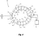
- the system 100 includes a plurality of simplex injectors 102, each with a solenoid valve 114 and a single fluid circuit as shown in either Figs. 1 or 2 .
- Each of the injectors 102 is connected in fluid communication with a single manifold 150 for supplying fuel to each injector 102 in the plurality of injectors 102.
- Another sub-set of injectors 152 are passive, duplex nozzles with primary circuits 113 for low turndown, as well as secondary circuits 110 configured to issue fuel together with the fluid circuits 112 of the simplex injector 102.
- a controller 154 is electrically connected to the solenoid valves 114 for individual control thereof (in Fig.
- solenoid valve 114 only one solenoid valve 114 is shown connected to the controller 154 for sake of clarity in the drawing). It is also contemplated that the controller 154 can instead be electrically connected to the solenoid valves 114 for ganged control thereof, i.e. where all the valves 114 receive the same command from the controller 154.
- the first sub-set of injectors 102 is grouped circumferentially offset from the second sub-set of injectors 152. In Fig. 4 , there are two groups of three solenoid controlled simplex injectors 102, separated circumferentially from one another by two sets of six passive duplex, injectors 152.
- control of the injectors 102 as described herein allows for finely tuned control of the flame in a combustor that is fed by the injectors 102, 152, and that the three solenoid controlled and six passive duplex injectors described here are an example and this disclosure applies to any other suitable combination of passive / active injectors.
- the control can be based on sensor feedback from one or more sensors 156 in the system 100.
- the solenoid valve can instead be a binary valve, a modulating valve, a motorized valve, or any other suitable type of valve, e.g. separate from the scheduling valve, such as a torque motor based servo valve with flapper and nozzle.
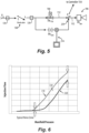
- the solenoid valve 114 described above with reference to Figs. 1-3 is a discrete open/closed valve even if a modulating type valve is used, however, with reference now to Fig. 5 , it is also contemplated that it can instead be a proportional valve 214, with intermediate conditions between fully open and fully closed.
- the proportional valve 214 includes a proportional solenoid, a torque motor based servo valve, or a stepper motor. If a stepper motor is used, multiple discrete steps can be used between fully open and fully closed.
- the check/metering valve or valves 138, 139 is/are upstream of the branch between the lines to the valve assembly 104 and to the proportional valve 214.
- the scheduling valve assembly 104 is in the fluid circuit 112 for control of flow through the fluid circuit 112. Proportionally controlling the separate valve 214 between fully opened and fully closed states allows for intermediate flow states for fine tuning as needed to combustion conditions.
- Fig. 6 shows a graph of injector flow rate versus manifold pressure for total flow through the injector through the inlet 108.
- the first line 310 shows the flow response over a range of manifold pressures with the separate valve 214 fully open, and the second line 320 shows the same but for the separate valve 214 fully closed.
- Proportional control between fully closed and fully opened allows fine tuning of the flow at a given manifold pressure to the area 330 between the two lines 310 and 320.
- each of the injectors 102 can include a mass flow sensor 259 embedded in contact with fuel passing through the injector 102/152 operatively connected to the controller 154 to provide mass flow feedback to the controller 154.
- the sensor signals can be used to control actuators of the electrically-controlled valves 214 to gain more / less uniformity as desired during operation.
- the sensor 259 can include several devices in isolation or combination, such as a hot wire anemometer, a pitot tube, an ultrasonic transducer, an NIST (National Institute of Standards and Technology) type calibration orifice, a thermocouple, a pressure transducer, a turbine wheel, a Coriolis meter, a chemiluminescence sensor for sensing a signal from flame, or any other suitable type of sensor.
- the sensor 259 is used to control flow in the circuit 112, so can be located anywhere in the circuit 112 upstream or downstream of the sub-circuit for the valve 214.
- valves can be set to reduce flow, others can be opened to increase flow to compensate.
- Incorporation of the one or more sensors 156 e.g. mass-flow sensors, pressure sensor(s), and/or position sensors, can allow for health monitoring and active flow control.
- the valves can be gradually actuated to minimize potential pressure spikes within the fuel system 100.
- failure of the electrically-controlled valve 114/214 results in limited flow to the simplex circuit, not total loss of the simplex circuit.
- Systems and methods as disclosed herein can allow for independent control of the simplex circuit to mitigate acoustics, emissions or flame out. Multiple valves can work together as a system, e.g.
- valves if one valve is set to reduce flow, others can be opened to increase flow to compensate as the system adapts to stabilize conditions in the combustor.
- Incorporation of mass-flow sensor, pressure sensor(s), and/or position sensor allows for health monitoring, and for active flow control. Proportional control allows for valves to be gradually actuated to minimize potential pressure spikes within the fuel system. Tailoring flow proportionally between full state switch can improve operability of the engine, including ignition, pull away, and noise mitigations.
Landscapes
- Engineering & Computer Science (AREA)
- Chemical & Material Sciences (AREA)
- Combustion & Propulsion (AREA)
- General Engineering & Computer Science (AREA)
- Mechanical Engineering (AREA)
- Magnetically Actuated Valves (AREA)
- Fuel-Injection Apparatus (AREA)
Applications Claiming Priority (2)
| Application Number | Priority Date | Filing Date | Title |
|---|---|---|---|
| US17/896,491 US20240068412A1 (en) | 2022-08-26 | 2022-08-26 | Force modification of passive spool for control of simplex circuit of fuel nozzles |
| US18/224,816 US20240068409A1 (en) | 2022-08-26 | 2023-07-21 | Proportional force modification of passive spool for control of simplex circuit of fuel nozzles |
Publications (2)
| Publication Number | Publication Date |
|---|---|
| EP4332361A1 true EP4332361A1 (fr) | 2024-03-06 |
| EP4332361B1 EP4332361B1 (fr) | 2026-03-25 |
Family
ID=87845584
Family Applications (1)
| Application Number | Title | Priority Date | Filing Date |
|---|---|---|---|
| EP23193571.9A Active EP4332361B1 (fr) | 2022-08-26 | 2023-08-25 | Modification de force proportionnelle de tiroir passif pour la commande d'un circuit simplex d'injecteurs de carburant |
Country Status (2)
| Country | Link |
|---|---|
| US (1) | US20240068409A1 (fr) |
| EP (1) | EP4332361B1 (fr) |
Citations (5)
| Publication number | Priority date | Publication date | Assignee | Title |
|---|---|---|---|---|
| US5732730A (en) | 1995-09-11 | 1998-03-31 | Delavan Inc | Combined check valve and metering valve assembly |
| EP2497923A2 (fr) * | 2011-03-11 | 2012-09-12 | Rolls-Royce Goodrich Engine Control Systems Ltd. | Système de carburant |
| US20130061599A1 (en) * | 2011-09-09 | 2013-03-14 | General Electric Company | Fuel manifold cooling flow recirculation |
| EP2597285A2 (fr) * | 2011-11-22 | 2013-05-29 | United Technologies Corporation | Distribution de mélange carburant-air pour des chambres de combustion de moteur à turbine à gaz |
| EP3070408A1 (fr) * | 2015-03-20 | 2016-09-21 | Rolls-Royce Controls and Data Services Limited | Système d'activation de combustion |
Family Cites Families (1)
| Publication number | Priority date | Publication date | Assignee | Title |
|---|---|---|---|---|
| US10450961B2 (en) * | 2016-06-17 | 2019-10-22 | Hamilton Sundstrand Corporation | Windmill bypass with shutoff signal |
-
2023
- 2023-07-21 US US18/224,816 patent/US20240068409A1/en not_active Abandoned
- 2023-08-25 EP EP23193571.9A patent/EP4332361B1/fr active Active
Patent Citations (5)
| Publication number | Priority date | Publication date | Assignee | Title |
|---|---|---|---|---|
| US5732730A (en) | 1995-09-11 | 1998-03-31 | Delavan Inc | Combined check valve and metering valve assembly |
| EP2497923A2 (fr) * | 2011-03-11 | 2012-09-12 | Rolls-Royce Goodrich Engine Control Systems Ltd. | Système de carburant |
| US20130061599A1 (en) * | 2011-09-09 | 2013-03-14 | General Electric Company | Fuel manifold cooling flow recirculation |
| EP2597285A2 (fr) * | 2011-11-22 | 2013-05-29 | United Technologies Corporation | Distribution de mélange carburant-air pour des chambres de combustion de moteur à turbine à gaz |
| EP3070408A1 (fr) * | 2015-03-20 | 2016-09-21 | Rolls-Royce Controls and Data Services Limited | Système d'activation de combustion |
Also Published As
| Publication number | Publication date |
|---|---|
| US20240068409A1 (en) | 2024-02-29 |
| EP4332361B1 (fr) | 2026-03-25 |
Similar Documents
| Publication | Publication Date | Title |
|---|---|---|
| US20240068412A1 (en) | Force modification of passive spool for control of simplex circuit of fuel nozzles | |
| US12134985B2 (en) | Force modification of passive spool for control of secondary nozzle circuits | |
| EP2339147B1 (fr) | Système de commande d'alimentation en carburant d'un moteur d'aéronef | |
| US12060831B1 (en) | Banked force modification for fuel nozzles | |
| US5339636A (en) | Fuel splitter valve assembly for gas turbine | |
| EP4134530B1 (fr) | Entraînement à modulation de largeur d'impulsion pour collecteurs de carburant étagés | |
| US11970977B2 (en) | Variable restriction of a secondary circuit of a fuel injector | |
| US11970976B2 (en) | Variable restriction of fuel nozzle with an auxiliary circuit | |
| EP4328438A1 (fr) | Limitation variable d'un circuit de carburant d'une buse de carburant | |
| EP4417797A1 (fr) | Commande proportionnelle de circuit de refroidissement d'injecteur de carburant | |
| EP4332361B1 (fr) | Modification de force proportionnelle de tiroir passif pour la commande d'un circuit simplex d'injecteurs de carburant | |
| US12313004B2 (en) | Proportional force modification of passive spool for control of secondary nozzle circuits | |
| EP4328437A1 (fr) | Modification de force de bobines de soupape passives pour la commande de buses | |
| US11913382B1 (en) | Variable restriction of a fuel circuit of a fuel nozzle | |
| EP4495406A1 (fr) | Limitation variable d'un circuit de carburant d'une buse de carburant | |
| US12305581B2 (en) | Proportional restriction of a secondary circuit of a fuel injector | |
| US12270343B2 (en) | Proportional restriction of fuel nozzle with an auxiliary circuit | |
| US20240271790A1 (en) | Variable cooling of secondary circuit of fuel nozzles | |
| US12454950B2 (en) | Direct control for variable displacement pumps using a bypass valve and a minimum pressure shutoff valve | |
| US7647776B1 (en) | Fluid flow control system | |
| GB2414767A (en) | Fuel control system |
Legal Events
| Date | Code | Title | Description |
|---|---|---|---|
| PUAI | Public reference made under article 153(3) epc to a published international application that has entered the european phase |
Free format text: ORIGINAL CODE: 0009012 |
|
| STAA | Information on the status of an ep patent application or granted ep patent |
Free format text: STATUS: THE APPLICATION HAS BEEN PUBLISHED |
|
| AK | Designated contracting states |
Kind code of ref document: A1 Designated state(s): AL AT BE BG CH CY CZ DE DK EE ES FI FR GB GR HR HU IE IS IT LI LT LU LV MC ME MK MT NL NO PL PT RO RS SE SI SK SM TR |
|
| STAA | Information on the status of an ep patent application or granted ep patent |
Free format text: STATUS: REQUEST FOR EXAMINATION WAS MADE |
|
| 17P | Request for examination filed |
Effective date: 20240822 |
|
| RBV | Designated contracting states (corrected) |
Designated state(s): AL AT BE BG CH CY CZ DE DK EE ES FI FR GB GR HR HU IE IS IT LI LT LU LV MC ME MK MT NL NO PL PT RO RS SE SI SK SM TR |
|
| GRAP | Despatch of communication of intention to grant a patent |
Free format text: ORIGINAL CODE: EPIDOSNIGR1 |
|
| STAA | Information on the status of an ep patent application or granted ep patent |
Free format text: STATUS: GRANT OF PATENT IS INTENDED |
|
| INTG | Intention to grant announced |
Effective date: 20251120 |
|
| RIN1 | Information on inventor provided before grant (corrected) |
Inventor name: WILLIAMS, BRANDON P. Inventor name: RYON, JASON A. Inventor name: HAUSJAAHABINK, TODD Inventor name: DLOKHANDWALLA, MURTUZA Inventor name: REUTER, CHARLES E. Inventor name: KOKAS, JAY W. Inventor name: VERSAILLES, RICHARD E. Inventor name: FERRAROTTI, MICHAEL Inventor name: ROURKE, RUSSELL P., JR |
|
| GRAS | Grant fee paid |
Free format text: ORIGINAL CODE: EPIDOSNIGR3 |
|
| GRAA | (expected) grant |
Free format text: ORIGINAL CODE: 0009210 |
|
| STAA | Information on the status of an ep patent application or granted ep patent |
Free format text: STATUS: THE PATENT HAS BEEN GRANTED |
|
| RIN1 | Information on inventor provided before grant (corrected) |
Inventor name: WILLIAMS, BRANDON P. Inventor name: RYON, JASON A. Inventor name: HAUSJAAHABINK, TODD Inventor name: LOKHANDWALLA, MURTUZA Inventor name: REUTER, CHARLES E. Inventor name: KOKAS, JAY W. Inventor name: VERSAILLES, RICHARD E. Inventor name: FERRAROTTI, MICHAEL Inventor name: ROURKE, RUSSELL P., JR |
|
| AK | Designated contracting states |
Kind code of ref document: B1 Designated state(s): AL AT BE BG CH CY CZ DE DK EE ES FI FR GB GR HR HU IE IS IT LI LT LU LV MC ME MK MT NL NO PL PT RO RS SE SI SK SM TR |
|
| REG | Reference to a national code |
Ref country code: CH Ref legal event code: F10 Free format text: ST27 STATUS EVENT CODE: U-0-0-F10-F00 (AS PROVIDED BY THE NATIONAL OFFICE) Effective date: 20260325 Ref country code: GB Ref legal event code: FG4D |
|
| REG | Reference to a national code |
Ref country code: DE Ref legal event code: R096 Ref document number: 602023013979 Country of ref document: DE |
|
| REG | Reference to a national code |
Ref country code: IE Ref legal event code: FG4D |