EP4332362A1 - Mit einem hydraulikmotor angetriebene kraftstoffsysteme mit variabler geschwindigkeit - Google Patents
Mit einem hydraulikmotor angetriebene kraftstoffsysteme mit variabler geschwindigkeit Download PDFInfo
- Publication number
- EP4332362A1 EP4332362A1 EP23193738.4A EP23193738A EP4332362A1 EP 4332362 A1 EP4332362 A1 EP 4332362A1 EP 23193738 A EP23193738 A EP 23193738A EP 4332362 A1 EP4332362 A1 EP 4332362A1
- Authority
- EP
- European Patent Office
- Prior art keywords
- fluid
- fuel
- pressure
- line
- fuel line
- Prior art date
- Legal status (The legal status is an assumption and is not a legal conclusion. Google has not performed a legal analysis and makes no representation as to the accuracy of the status listed.)
- Pending
Links
- 239000000446 fuel Substances 0.000 title claims abstract description 168
- 239000012530 fluid Substances 0.000 claims abstract description 153
- 239000002828 fuel tank Substances 0.000 claims abstract description 16
- 230000001105 regulatory effect Effects 0.000 claims description 45
- 238000011144 upstream manufacturing Methods 0.000 claims description 9
- 238000000034 method Methods 0.000 claims description 7
- 230000001276 controlling effect Effects 0.000 claims description 5
- 230000007423 decrease Effects 0.000 description 4
- 238000005086 pumping Methods 0.000 description 3
- 230000003247 decreasing effect Effects 0.000 description 2
- 238000010586 diagram Methods 0.000 description 2
- 230000006870 function Effects 0.000 description 1
- 238000012986 modification Methods 0.000 description 1
- 230000004048 modification Effects 0.000 description 1
Images

Classifications
-
- F—MECHANICAL ENGINEERING; LIGHTING; HEATING; WEAPONS; BLASTING
- F04—POSITIVE - DISPLACEMENT MACHINES FOR LIQUIDS; PUMPS FOR LIQUIDS OR ELASTIC FLUIDS
- F04D—NON-POSITIVE-DISPLACEMENT PUMPS
- F04D13/00—Pumping installations or systems
- F04D13/02—Units comprising pumps and their driving means
- F04D13/04—Units comprising pumps and their driving means the pump being fluid driven
-
- F—MECHANICAL ENGINEERING; LIGHTING; HEATING; WEAPONS; BLASTING
- F02—COMBUSTION ENGINES; HOT-GAS OR COMBUSTION-PRODUCT ENGINE PLANTS
- F02C—GAS-TURBINE PLANTS; AIR INTAKES FOR JET-PROPULSION PLANTS; CONTROLLING FUEL SUPPLY IN AIR-BREATHING JET-PROPULSION PLANTS
- F02C9/00—Controlling gas-turbine plants; Controlling fuel supply in air- breathing jet-propulsion plants
- F02C9/26—Control of fuel supply
- F02C9/30—Control of fuel supply characterised by variable fuel pump output
-
- B—PERFORMING OPERATIONS; TRANSPORTING
- B64—AIRCRAFT; AVIATION; COSMONAUTICS
- B64D—EQUIPMENT FOR FITTING IN OR TO AIRCRAFT; FLIGHT SUITS; PARACHUTES; ARRANGEMENT OR MOUNTING OF POWER PLANTS OR PROPULSION TRANSMISSIONS IN AIRCRAFT
- B64D37/00—Arrangements in connection with fuel supply for power plant
- B64D37/005—Accessories not provided for in the groups B64D37/02 - B64D37/28
-
- F—MECHANICAL ENGINEERING; LIGHTING; HEATING; WEAPONS; BLASTING
- F02—COMBUSTION ENGINES; HOT-GAS OR COMBUSTION-PRODUCT ENGINE PLANTS
- F02C—GAS-TURBINE PLANTS; AIR INTAKES FOR JET-PROPULSION PLANTS; CONTROLLING FUEL SUPPLY IN AIR-BREATHING JET-PROPULSION PLANTS
- F02C7/00—Features, components parts, details or accessories, not provided for in, or of interest apart form groups F02C1/00 - F02C6/00; Air intakes for jet-propulsion plants
- F02C7/22—Fuel supply systems
- F02C7/236—Fuel delivery systems comprising two or more pumps
-
- F—MECHANICAL ENGINEERING; LIGHTING; HEATING; WEAPONS; BLASTING
- F04—POSITIVE - DISPLACEMENT MACHINES FOR LIQUIDS; PUMPS FOR LIQUIDS OR ELASTIC FLUIDS
- F04D—NON-POSITIVE-DISPLACEMENT PUMPS
- F04D15/00—Control, e.g. regulation, of pumps, pumping installations or systems
- F04D15/0005—Control, e.g. regulation, of pumps, pumping installations or systems by using valves
-
- F—MECHANICAL ENGINEERING; LIGHTING; HEATING; WEAPONS; BLASTING
- F05—INDEXING SCHEMES RELATING TO ENGINES OR PUMPS IN VARIOUS SUBCLASSES OF CLASSES F01-F04
- F05D—INDEXING SCHEME FOR ASPECTS RELATING TO NON-POSITIVE-DISPLACEMENT MACHINES OR ENGINES, GAS-TURBINES OR JET-PROPULSION PLANTS
- F05D2270/00—Control
- F05D2270/01—Purpose of the control system
- F05D2270/02—Purpose of the control system to control rotational speed (n)
-
- F—MECHANICAL ENGINEERING; LIGHTING; HEATING; WEAPONS; BLASTING
- F05—INDEXING SCHEMES RELATING TO ENGINES OR PUMPS IN VARIOUS SUBCLASSES OF CLASSES F01-F04
- F05D—INDEXING SCHEME FOR ASPECTS RELATING TO NON-POSITIVE-DISPLACEMENT MACHINES OR ENGINES, GAS-TURBINES OR JET-PROPULSION PLANTS
- F05D2270/00—Control
- F05D2270/30—Control parameters, e.g. input parameters
- F05D2270/301—Pressure
- F05D2270/3011—Inlet pressure
-
- F—MECHANICAL ENGINEERING; LIGHTING; HEATING; WEAPONS; BLASTING
- F05—INDEXING SCHEMES RELATING TO ENGINES OR PUMPS IN VARIOUS SUBCLASSES OF CLASSES F01-F04
- F05D—INDEXING SCHEME FOR ASPECTS RELATING TO NON-POSITIVE-DISPLACEMENT MACHINES OR ENGINES, GAS-TURBINES OR JET-PROPULSION PLANTS
- F05D2270/00—Control
- F05D2270/50—Control logic embodiments
- F05D2270/56—Control logic embodiments by hydraulic means, e.g. hydraulic valves within a hydraulic circuit
Definitions
- the present disclosure relates to fuel systems, and more particularly to variable speed hydraulic motor driven fuel systems.
- Hydraulic motor driven pumping systems driven by hydraulic fluid or fuel can be included in various locations in aircraft fuel systems. Such systems are typically fed a constant flow and pressure which results in a consistent speed at given flight conditions. Constant flow and pressure hydraulic pumping systems are often sized for the worst-case condition and then will provide excessive flow/pressure at all other conditions. This can result in an inefficient system, in certain instances.
- a system in accordance with at least one aspect of this disclosure, includes a fuel line defining a fuel inlet and a fuel outlet, configured to provide fuel from a fuel tank to an engine.
- a boost pump including a boost impeller, is disposed in the fuel line configured to drive fuel from the fuel inlet to the fuel outlet.
- the system includes a fluid line defining a fluid inlet and a fluid outlet, configured to provide fluid from a fluid source to a fluid destination.
- a fluid turbine is disposed in the fluid line configured to alter a pressure of the fuel line at the fuel outlet. The fluid turbine can be operatively connected to the boost pump via a drive shaft.
- a regulating valve is disposed in the fluid line upstream of the fluid turbine configured to control a pressure of the fluid line to control the speed of the fluid turbine.
- a controllable valve is fluidly connected to the fuel line and to the fluid line configured to control a flow of fluid to the regulating valve based at least in part on a pressure in the fuel line and/or a command from an airframe or engine controller.
- the regulating valve can be or include a bypass regulating valve configured to control a pressure in the fluid line by controlling an amount of bypass discharge.
- the bypass regulating valve In a first position, the bypass regulating valve can be configured to pass flow from the fluid source and the controllable valve to the fluid line and to bypass a portion of flow to a bypass outlet based at least in part on flow from the controllable valve. In a second position, the bypass regulating valve can be configured to prevent flow from passing from the fluid source to the fluid line.
- bypass regulating valve moves from the first position to the second position (e.g., opens) pressure in the fluid line will decrease, flow to the fluid turbine will decrease and the speed of the fluid turbine will decrease in turn, altering the speed of the fuel pump which decreases the pressure at the discharge of the boost pump.
- a pressure sensor can be disposed in the fuel line configured to sense and output a signal indicative of a pressure in the fuel line, and a controller can be operatively connected to receive the signal indicative of a pressure in the fuel line and control the controllable valve based at least in part on the signal indicative of the pressure in the fuel line.
- the system can include a controller configured to control the controllable valve to control flow to the fluid turbine to alter the pressure in the fuel line based at least in part on a required pressure setting for the fuel line for a given engine condition.
- the regulating valve can be or include a pressure compensation valve configured to control a pressure in the fluid line.
- the pressure compensation valve in a first position, can be configured to pass flow from the fluid source and the controllable valve to the fluid line and to bypass a portion of flow to a bypass outlet based at least in part on discharge pressure feedback from the boost pump. In a second position, the pressure compensation valve can be configured to prevent flow from passing from the fluid source to the fluid line.
- bypass regulating valve moves from the second positon to the first positon (e.g., closes) pressure in the fluid line will increase, flow to the fluid turbine will increase and the speed of the fluid turbine will increase in turn, altering the speed of a fuel pump which increases the pressure in the fuel line to increase the boost pressure.
- a pressure sensor disposed in the fuel line configured to sense and output a signal indicative of a pressure in the fuel line
- a controller can be operatively connected to receive the signal indicative of a pressure in the fuel line and control the pressure compensation valve based at least in part on the signal indicative of the pressure in the fuel line to alter the pressure in the fuel line based at least in part on a required pressure setting for the fuel line for a given engine condition.
- the fuel line can be a first fuel line
- the fuel inlet can be a first fuel inlet
- the fuel outlet can be a first fuel outlet.
- the boost pump can further include a second boost impeller disposed in a second fuel line between a second fuel inlet and a second fuel outlet.
- the fluid turbine can be disposed in the fluid line between the first fuel line and the second fuel line, and is configured to alter a pressure of the first fuel line and the second fuel line.
- controllable valve can include an electrohydraulic servo valve.
- the fluid can include hydraulic fluid and the fluid turbine can include a hydraulic pump.
- the fluid can include oil, such as gearbox oil.
- the fluid can include fuel and the fluid turbine can include a fueldraulic pump.
- the system can include the fuel tank and the engine and the boost pump can be disposed in the fuel tank, and can be upstream from any engine boost pump(s).
- a method includes altering, with a fluid motor, a discharge pressure of a boost pump in a fuel line upstream of an engine while the boost pump is operating. Altering can include providing fluid to the fluid motor via a regulating valve disposed in a fluid line to control a speed of a fluid turbine of the fluid motor.
- the regulating valve can include a bypass regulating valve, and in such embodiments, altering can include providing flow to the bypass regulating valve through a controllable valve based at least in part on pressure feedback from the fuel line and/or an engine command.
- the regulating valve can include a pressure compensating valve, and in such embodiments, altering can include providing flow to the pressure compensation valve through a controllable valve based at least in part on pressure feedback from the fuel line and/or an engine command.
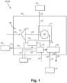
- FIG. 1 an illustrative view of an embodiment of a system in accordance with the disclosure is shown in Fig. 1 and is designated generally by reference character 100.
- FIG. 2 Other embodiments and/or aspects of this disclosure are shown in Fig. 2 .
- Certain embodiments described herein can be used to actively vary a fuel discharge pressure in a fuel system.
- a system 100 can include a fuel tank 102 (e.g., of an aircraft) fluidly connected to provide fuel to an engine 104 via a fuel line 106.
- a boost pump 108 can be disposed in the fuel tank 102 to boost the pressure in the fuel line 106 to provide higher pressure fuel to the engine 104.
- the boost pump 108 can be upstream from any engine boost pump(s).
- the fuel line 106 defines a fuel inlet 110 and a fuel outlet 112 (e.g., into the boost pump 108 and out of the fuel tank 102), to provide the fuel from the fuel tank 102 to the engine 104.
- the boost pump 108 can include a boost impeller 114 disposed in the fuel line 106 configured to drive fuel from the fuel inlet 110 to the fuel outlet 112, boosting the discharge pressure in the fuel line 106 at an outlet 116 of the boost pump 108.
- the system 100 includes a fluid line 118 defining a fluid inlet 120 and a fluid outlet 122, configured to provide fluid from a fluid source 124 to a fluid destination 126 (e.g., one or more downstream fuel system components or a gearbox).
- the fluid can include hydraulic fluid, oil (e.g., gearbox oil), or the fluid can include fuel if the system includes a fueldraulic system.
- the boost pump 108 can be included in an airframe and the fluid destination 126 an engine fuel system.
- the boost pump 108 can be included in the engine and the fluid destination 126 can include a fuel filter and/or one or more exchangers.
- a fluid motor 127 having a fluid turbine 128 can be disposed in the fluid line 118 and operatively connected to the boost pump via a drive shaft 119, the fluid turbine 128 configured to alter the rotational speed of the impeller 114 to create a pressure at the fuel outlet 112, to selectively raise the discharge pressure of the fuel in the fuel line 112 provided to the engine from the boost pump 108.
- a regulating valve 130 can be disposed in the fluid line 118 upstream of the fluid turbine 128 configured to control the amount of flow and pressure of the fluid line 118 to control the speed of the fluid turbine 128.
- a controllable valve 132 such as an electronically controllable or otherwise command able valve (e.g., an EHSV), can be fluidly connected to the fuel line 106 and/or to the fluid line 118 (e.g., via the regulating valve).
- the controllable valve 132 can be supplied with a supply pressure 134 and can control a flow of fluid to the regulating valve 130 based at least in part on a pressure in the fuel line and/or a command from an airframe or engine controller 136.
- the boost impeller 114 can take fuel from the fuel tank 102 to boost the pressure to deliver to the engine 104 and the boost impeller 114 can be driven by the fluid turbine 128 via the mechanical drive shaft 119 between the turbine 128 and the boost impeller 114.
- the fluid turbine 128 can be driven by a fluid flow (e.g., in fluid line 118), which is controlled by valve 130.
- a fluid flow e.g., in fluid line 118
- one or more shaft seals may be included on the drive shaft 119, and there is no fuel connection between the fuel line 106 and the controllable valve 132.
- fuel is discharged from the boost impeller 114 out to be sensed by a pressure transducer 142 (e.g. as described below) and feeds the controllable valve 132 as a supply pressure and then flows out to the engine 104.
- a pressure transducer 142 e.g. as described below
- the engine command can include a required pressure setting for a given engine condition.
- the regulating valve 130 can be or include a bypass regulating valve configured to control a pressure in the fluid line 118 by controlling an amount of bypass discharge 138.
- the regulating valve 130 can be or include a pressure compensation valve configured to control a pressure in the fluid line 118 by controlling an amount of bypass discharge 138 based on the required pressure setting for the given engine condition.
- the regulating valve 130 In a first position (e.g., an open position), the regulating valve 130 can be configured to pass flow from the fluid source 124 and the controllable valve 132 to the fluid line 118 and to bypass a portion of flow to a bypass outlet 140 based at least in part on flow from the controllable valve 132. In a second position (e.g., a bypass position), the regulating valve 130 can be configured to prevent flow from passing from the fluid source 124 to the fluid line 118 and instead pass all fluid to the bypass outlet 140 as bypass discharge 138, slowing the speed of the fluid turbine 128.
- a first position e.g., an open position
- the regulating valve 130 In a second position (e.g., a bypass position), the regulating valve 130 can be configured to prevent flow from passing from the fluid source 124 to the fluid line 118 and instead pass all fluid to the bypass outlet 140 as bypass discharge 138, slowing the speed of the fluid turbine 128.
- a pressure sensor 142 (e.g., a pressure transducer) can be disposed in the fuel line 106 downstream of the boost impeller 114, configured to sense and output a signal 144 indicative of a pressure in the fuel line 106.
- the controller 136 can be operatively connected to receive the signal indicative of a pressure in the fuel line 106 and can be configured to control the controllable valve 132 based at least in part on the signal indicative of the pressure in the fuel line 106 via control signal 146.
- the controller 136 can also be configured to control the controllable valve 132 to control flow to the fluid turbine 128 to alter the pressure in the fuel line 106 based at least in part on a required pressure setting for the fuel line for a given engine condition, either together with or independent of the pressure sensor reading 144.
- the controller 136 can include an existing engine or airframe controller additionally programmed to control the controllable valve (e.g., an existing FADEC), or the controller 136 can be an additional controller dedicated to controlling the controllable valve 132.
- a system 200 can be similar to that of system 100, for example system 200 can have similar components and features with respect to systems 100.
- system 200 can have similar components and features with respect to systems 100.
- the description of common elements that have been described above for system 100 are not repeated with respect to system 200 as shown in Fig. 2 .
- the fuel line 106 can be a first fuel line 106
- the fuel inlet 110 can be a first fuel inlet 110
- the fuel outlet 112 can be a first fuel outlet 112
- the boost pump 208 can further include a second boost impeller 214 disposed in a second fuel line 206 between a second fuel inlet 210 and a second fuel outlet 212.
- the fluid turbine 228 can be disposed in the fluid line 118 between the first fuel line 106 and the second fuel line 206.
- the fluid turbine 228 can be mechanically connected to each of the boost impellers 114, 214 via drive shaft(s) 119, 219 and can be is configured to alter a pressure of both the first fuel line 106 and the second fuel line 206 at the same time.
- the controllable valve 132, the regulating valve 130, and the pressure sensor 142 can be used in the same or similar manner as described above with respect to system 100 and may be additionally connected to the second fuel line 206 in a similar manner as with respect to the first fuel line 106. However, in certain embodiments, if a pressure compensation valve is used for the regulating valve 130, the pressure compensation valve is also fluidly connected to the second fuel line 206, while a bypass regulating valve would not be so connected to the second fuel line 206.
- a method 300 can include altering, with a fluid motor (e.g., fluid motor 127, 227), a discharge pressure of a boost pump (e.g., boost pump 108, 208) in a fuel line (e.g., fuel line 106) upstream of an engine while the boost pump is operating.
- Altering can include providing fluid to the fluid motor via a regulating valve (e.g., regulating valve 130) disposed in a fluid line (e.g., fluid line 118) to control a speed of a fluid turbine (e.g., turbine 128, 228) of the fluid motor.
- the regulating valve can include a bypass regulating valve, and in such embodiments, altering can include providing flow to the bypass regulating valve through a controllable valve (e.g., controllable valve 132) based at least in part on pressure feedback (e.g., feedback from sensor 142) from the fuel line and/or an engine command (e.g., command 146 from controller 136).
- a controllable valve e.g., controllable valve 132
- pressure feedback e.g., feedback from sensor 142
- an engine command e.g., command 146 from controller 136
- the regulating valve can include a pressure compensating valve, and in such embodiments, altering can include providing flow to the pressure compensation valve through a controllable valve (e.g., controllable valve 132) based at least in part on pressure feedback (e.g., feedback from sensor 142) from the fuel line and/or an engine command (e.g., command 146 from controller 136).
- a controllable valve e.g., controllable valve 132
- pressure feedback e.g., feedback from sensor 142
- an engine command e.g., command 146 from controller 136
- Embodiments include a variable fluid driven boost pump to selectively vary fuel discharge pressure from a fuel tank boost pump to improve efficiency and minimize losses during variable engine conditions.
- the system 100, 200 allows for selectively decreasing the boost pressure while the pump is operating by varying flow in the fluid line.
- the system 100, 200 can increase the boost pressure at the outlet of the fuel tank by varying flow in the fluid line.
- the fluid line and fluid turbine operate selectively, either as a function of an engine command, a required pressure setting, or the pressure in the fuel line, and therefore does not change the pressure in the fuel line for the entire duty cycle.
- Additional flow to the fluid line is provided only when needed and does not require the main fuel tank boost pumps to be sized for the highest pressure (e.g., take-off or max climb).
- the fluid turbine uses fuel draw from the engine to control pressure in the fuel line at the outlet of the fuel tank, rather than an electronic motor driven pump.
- Boost pumps or electric motor pumps may be sized for the worst case condition, and typically operate at a single speed.
- Embodiments can include a bypass regulating valve with control from an electrohydraulic servo valve that is controlled by an engine controller or other computing means on-aircraft to actively adjust fuel pressure upstream of the engine, while the pumps are operating to allow for a variable speed boost pump.
- Embodiments can include a pressure compensation valve that receives discharge pressure feedback from the boost pump and controls the flow to the fluid motor based upon a required pressure setting.
- the speed of the boost pumps described herein can be adjusted to meet the pressure needs of the system and therefore can have a higher overall efficiency than conventional boost pumps. Further, the systems as disclosed herein do not create more pressure than needed and thus do not draw more horsepower than needed, unlike single speed boost pumps which may generate more pressure and heat than is necessary for the system at a given operating condition.
- any numerical values disclosed herein can be exact values or can be values within a range. Further, any terms of approximation (e.g., “about”, “approximately”, “around”) used in this disclosure can mean the stated value within a range. For example, in certain embodiments, the range can be within (plus or minus) 20%, or within 10%, or within 5%, or within 2%, or within any other suitable percentage or number as appreciated by those having ordinary skill in the art (e.g., for known tolerance limits or error ranges).
- a reference to "A and/or B", when used in conjunction with open-ended language such as “comprising” can refer, in one embodiment, to A only (optionally including elements other than B); in another embodiment, to B only (optionally including elements other than A); in yet another embodiment, to both A and B (optionally including other elements); etc.
Landscapes
- Engineering & Computer Science (AREA)
- Mechanical Engineering (AREA)
- General Engineering & Computer Science (AREA)
- Chemical & Material Sciences (AREA)
- Combustion & Propulsion (AREA)
- Aviation & Aerospace Engineering (AREA)
- Structures Of Non-Positive Displacement Pumps (AREA)
Applications Claiming Priority (1)
| Application Number | Priority Date | Filing Date | Title |
|---|---|---|---|
| US17/898,412 US20240068478A1 (en) | 2022-08-29 | 2022-08-29 | Variable speed hydraulic motor driven fuel systems |
Publications (1)
| Publication Number | Publication Date |
|---|---|
| EP4332362A1 true EP4332362A1 (de) | 2024-03-06 |
Family
ID=87847943
Family Applications (1)
| Application Number | Title | Priority Date | Filing Date |
|---|---|---|---|
| EP23193738.4A Pending EP4332362A1 (de) | 2022-08-29 | 2023-08-28 | Mit einem hydraulikmotor angetriebene kraftstoffsysteme mit variabler geschwindigkeit |
Country Status (2)
| Country | Link |
|---|---|
| US (1) | US20240068478A1 (de) |
| EP (1) | EP4332362A1 (de) |
Citations (4)
| Publication number | Priority date | Publication date | Assignee | Title |
|---|---|---|---|---|
| GB735874A (en) * | 1952-05-20 | 1955-08-31 | Rolls Royce | Improvements relating to gas-turbine engine fuel systems |
| GB896184A (en) * | 1959-03-26 | 1962-05-09 | Lucas Industries Ltd | Aircraft fuel supply systems |
| US20150114477A1 (en) * | 2012-04-18 | 2015-04-30 | Eaton Limited | Aircraft fuel supply systems |
| US20210070464A1 (en) * | 2018-05-08 | 2021-03-11 | Eaton Intelligent Power Limited | Fuel boost pump assembly for an aircraft |
Family Cites Families (35)
| Publication number | Priority date | Publication date | Assignee | Title |
|---|---|---|---|---|
| US2409245A (en) * | 1944-08-12 | 1946-10-15 | Glenn L Martin Co | Fuel system |
| US2706888A (en) * | 1949-03-10 | 1955-04-26 | Rolls Royce | Pump arrangements for gas-turbine engine fuel systems |
| US2855751A (en) * | 1949-03-10 | 1958-10-14 | Rolls Royce | Pump arrangements for gas-turbine engine fuel systems |
| US2658331A (en) * | 1950-02-16 | 1953-11-10 | Bendix Aviat Corp | Ram-jet launching sequence fuel flow control valve |
| US3080823A (en) * | 1951-11-15 | 1963-03-12 | Nash Engineering Co | Booster pumps |
| US2932946A (en) * | 1952-05-20 | 1960-04-19 | Rolls Royce | Fuel system for gas turbine engine including hydraulically driven auxillary pump |
| US2863395A (en) * | 1953-08-25 | 1958-12-09 | Thompson Prod Inc | Two stage air turbine driven fuel pump |
| US2916875A (en) * | 1953-09-09 | 1959-12-15 | Rolls Royce | Gas turbine engine fuel systems |
| US2874766A (en) * | 1954-07-07 | 1959-02-24 | Dowty Fuel Syst Ltd | Liquid fuel supply systems for gas turbine engines |
| US2936714A (en) * | 1956-07-18 | 1960-05-17 | Crane Co | Turbine driven pump |
| US2956502A (en) * | 1957-10-23 | 1960-10-18 | Curtiss Wright Corp | Fuel pump |
| US3150600A (en) * | 1958-07-07 | 1964-09-29 | Flo Motive Corp | Fluid handling device |
| US3060998A (en) * | 1959-03-26 | 1962-10-30 | Lucas Industries Ltd | Aircraft fuel supply systems |
| US3132594A (en) * | 1961-07-12 | 1964-05-12 | Thompson Ramo Wooldridge Inc | Liquid hydrogen turbopump |
| US4205945A (en) * | 1974-11-29 | 1980-06-03 | General Electric Company | Unitized fluid delivery system and method of operating same |
| DE2702590C2 (de) * | 1977-01-22 | 1981-09-17 | MTU Motoren- und Turbinen-Union München GmbH, 8000 München | Brennstoffsteuereinrichtung für ein Gasturbinentriebwerk |
| US4915593A (en) * | 1987-12-24 | 1990-04-10 | Sundstrand Corporation | Fluid supply system with turbine driven start pump |
| US4864815A (en) * | 1987-12-24 | 1989-09-12 | Sundstrand Corporation | Fuel supply system with turbine driven start pump |
| GB8801037D0 (en) * | 1988-01-18 | 1988-02-17 | Plessey Co Ltd | Improvements relating to fuel supply systems |
| US4922710A (en) * | 1989-01-04 | 1990-05-08 | General Electric Company | Integrated boost compressor/gas turbine control |
| FR2782544B1 (fr) * | 1998-08-19 | 2005-07-08 | Air Liquide | Pompe pour un liquide cryogenique ainsi que groupe de pompage et colonne de distillation equipes d'une telle pompe |
| CH699804A1 (de) * | 2008-10-29 | 2010-04-30 | Alstom Technology Ltd | Gasturbinenanlage mit Abgasrückführung sowie Verfahren zum Betrieb einer solchen Anlage. |
| US8276360B2 (en) * | 2009-05-22 | 2012-10-02 | Hamilton Sundstrand Corporation | Dual-pump fuel system and method for starting a gas turbine engine |
| US8584441B2 (en) * | 2010-01-05 | 2013-11-19 | Honeywell International Inc. | Fuel metering system electrically servoed metering pump |
| US20140219826A1 (en) * | 2011-08-15 | 2014-08-07 | Eaton Corporation | Fuel system using dual pressure hi-speed centrifugal pump arrangement |
| GB201117941D0 (en) * | 2011-10-18 | 2011-11-30 | Airbus Operations Ltd | Fuel tank installation |
| US20140294559A1 (en) * | 2013-03-28 | 2014-10-02 | Solar Turbines Incorporated | Multiple mode gas turbine engine gas fuel system with integrated control |
| US9874208B2 (en) * | 2015-01-21 | 2018-01-23 | Hamilton Sunstrand Corporation | Bearing faces with fluid channels for gear pumps |
| CA2923199C (en) * | 2015-03-12 | 2023-07-04 | Rolls-Royce Corporation | Return flow powered turbine |
| US9909468B2 (en) * | 2015-08-25 | 2018-03-06 | Caterpillar Inc. | Fluid conditioning system with recirculation loop and method for operating same |
| JP6923069B2 (ja) * | 2018-03-08 | 2021-08-18 | 株式会社Ihi | 燃料供給制御装置 |
| US20210079848A1 (en) * | 2019-03-20 | 2021-03-18 | United Technologies Corporation | Secondary fuel flow demand fuel pumping system |
| US11815021B2 (en) * | 2020-02-05 | 2023-11-14 | Turbogen Ltd. | Boosting CCHP gas turbine system |
| US12442397B2 (en) * | 2021-05-27 | 2025-10-14 | Eaton Intelligent Power Limited | Overspeed safeguards in hydraulically controlled fuel boost pump |
| GB202219409D0 (en) * | 2022-12-21 | 2023-02-01 | Rolls Royce Plc | Fuel management system |
-
2022
- 2022-08-29 US US17/898,412 patent/US20240068478A1/en not_active Abandoned
-
2023
- 2023-08-28 EP EP23193738.4A patent/EP4332362A1/de active Pending
Patent Citations (4)
| Publication number | Priority date | Publication date | Assignee | Title |
|---|---|---|---|---|
| GB735874A (en) * | 1952-05-20 | 1955-08-31 | Rolls Royce | Improvements relating to gas-turbine engine fuel systems |
| GB896184A (en) * | 1959-03-26 | 1962-05-09 | Lucas Industries Ltd | Aircraft fuel supply systems |
| US20150114477A1 (en) * | 2012-04-18 | 2015-04-30 | Eaton Limited | Aircraft fuel supply systems |
| US20210070464A1 (en) * | 2018-05-08 | 2021-03-11 | Eaton Intelligent Power Limited | Fuel boost pump assembly for an aircraft |
Also Published As
| Publication number | Publication date |
|---|---|
| US20240068478A1 (en) | 2024-02-29 |
Similar Documents
| Publication | Publication Date | Title |
|---|---|---|
| US8256222B2 (en) | Direct metering fuel control with integral electrical metering pump and actuator servo pump | |
| US9353688B2 (en) | High pressure, multiple metering zone gas turbine engine fuel supply system | |
| US8166765B2 (en) | Fuel delivery and control system including a variable displacement actuation pump supplementing a fixed displacement main pump | |
| EP3232036B1 (de) | Doppelpumpen-kraftstoffsystem mit pumpenteilungsverbindung | |
| EP2356329B1 (de) | Kraftstoffzufuhr- und steuersystem | |
| EP3020941B1 (de) | Flugzeugkraftstoffsystem | |
| US8291886B2 (en) | Actuator flow compensated direct metering fuel control system and method | |
| US8127548B2 (en) | Hybrid electrical/mechanical turbine engine fuel supply system | |
| EP4296492A1 (de) | Doppelpumpen-kraftstoffversorgung für ein flugzeug | |
| US9885287B2 (en) | Gas turbine engine mechanical-electrical hybrid fuel delivery system | |
| EP2891781B1 (de) | Motorkraftstoffsteuersystem | |
| US8286432B2 (en) | Electric power generating turbine engine fuel supply system | |
| US9453463B2 (en) | High efficiency, high pressure gas turbine engine fuel supply system | |
| US8739811B2 (en) | Direct metering fuel system with constant servo flow | |
| JP2016503861A (ja) | 複式ポンプ/複式バイパス燃料ポンプシステム | |
| RU2674301C2 (ru) | Подающий текучую среду контур с устройствами изменяемой геометрии и без объемного насоса для турбомашины | |
| EP2891768A1 (de) | Motorkraftstoffsteuerungssystem | |
| US20140219826A1 (en) | Fuel system using dual pressure hi-speed centrifugal pump arrangement | |
| CN112334385A (zh) | 用于电液伺服致动器,特别是涡轮螺旋桨发动机的控制系统和方法 | |
| EP2025901B1 (de) | Kraftstoffzumessystem mit minimaler Wärmezuführung | |
| US10934889B2 (en) | System and method for supplying lubrication fluid to at least one member of an aircraft propulsion assembly | |
| EP4332362A1 (de) | Mit einem hydraulikmotor angetriebene kraftstoffsysteme mit variabler geschwindigkeit | |
| CN104755758B (zh) | 离心式泵送和计量系统中的变排量泵的流体力学式压力补偿控制装置及相关方法 | |
| EP4166773B1 (de) | Flugzeugkraftstoffsystem mit geschlossenem regelkreis für elektrische kraftstoffregelung | |
| EP4191039B1 (de) | Kraftstoffpumpensysteme |
Legal Events
| Date | Code | Title | Description |
|---|---|---|---|
| PUAI | Public reference made under article 153(3) epc to a published international application that has entered the european phase |
Free format text: ORIGINAL CODE: 0009012 |
|
| STAA | Information on the status of an ep patent application or granted ep patent |
Free format text: STATUS: THE APPLICATION HAS BEEN PUBLISHED |
|
| AK | Designated contracting states |
Kind code of ref document: A1 Designated state(s): AL AT BE BG CH CY CZ DE DK EE ES FI FR GB GR HR HU IE IS IT LI LT LU LV MC ME MK MT NL NO PL PT RO RS SE SI SK SM TR |
|
| STAA | Information on the status of an ep patent application or granted ep patent |
Free format text: STATUS: REQUEST FOR EXAMINATION WAS MADE |
|
| 17P | Request for examination filed |
Effective date: 20240827 |
|
| RBV | Designated contracting states (corrected) |
Designated state(s): AL AT BE BG CH CY CZ DE DK EE ES FI FR GB GR HR HU IE IS IT LI LT LU LV MC ME MK MT NL NO PL PT RO RS SE SI SK SM TR |