EP4332397B1 - Roulement à billes à gorges profondes - Google Patents
Roulement à billes à gorges profondes Download PDFInfo
- Publication number
- EP4332397B1 EP4332397B1 EP21947883.1A EP21947883A EP4332397B1 EP 4332397 B1 EP4332397 B1 EP 4332397B1 EP 21947883 A EP21947883 A EP 21947883A EP 4332397 B1 EP4332397 B1 EP 4332397B1
- Authority
- EP
- European Patent Office
- Prior art keywords
- retainer
- connecting block
- sub
- connector
- insertion protrusion
- Prior art date
- Legal status (The legal status is an assumption and is not a legal conclusion. Google has not performed a legal analysis and makes no representation as to the accuracy of the status listed.)
- Active
Links
Images



Classifications
-
- F—MECHANICAL ENGINEERING; LIGHTING; HEATING; WEAPONS; BLASTING
- F16—ENGINEERING ELEMENTS AND UNITS; GENERAL MEASURES FOR PRODUCING AND MAINTAINING EFFECTIVE FUNCTIONING OF MACHINES OR INSTALLATIONS; THERMAL INSULATION IN GENERAL
- F16C—SHAFTS; FLEXIBLE SHAFTS; ELEMENTS OR CRANKSHAFT MECHANISMS; ROTARY BODIES OTHER THAN GEARING ELEMENTS; BEARINGS
- F16C19/00—Bearings with rolling contact, for exclusively rotary movement
- F16C19/02—Bearings with rolling contact, for exclusively rotary movement with bearing balls essentially of the same size in one or more circular rows
- F16C19/04—Bearings with rolling contact, for exclusively rotary movement with bearing balls essentially of the same size in one or more circular rows for radial load mainly
- F16C19/06—Bearings with rolling contact, for exclusively rotary movement with bearing balls essentially of the same size in one or more circular rows for radial load mainly with a single row or balls
-
- F—MECHANICAL ENGINEERING; LIGHTING; HEATING; WEAPONS; BLASTING
- F16—ENGINEERING ELEMENTS AND UNITS; GENERAL MEASURES FOR PRODUCING AND MAINTAINING EFFECTIVE FUNCTIONING OF MACHINES OR INSTALLATIONS; THERMAL INSULATION IN GENERAL
- F16C—SHAFTS; FLEXIBLE SHAFTS; ELEMENTS OR CRANKSHAFT MECHANISMS; ROTARY BODIES OTHER THAN GEARING ELEMENTS; BEARINGS
- F16C33/00—Parts of bearings; Special methods for making bearings or parts thereof
- F16C33/30—Parts of ball or roller bearings
- F16C33/38—Ball cages
- F16C33/3812—Ball cages formed of interconnected segments, e.g. chains
-
- F—MECHANICAL ENGINEERING; LIGHTING; HEATING; WEAPONS; BLASTING
- F16—ENGINEERING ELEMENTS AND UNITS; GENERAL MEASURES FOR PRODUCING AND MAINTAINING EFFECTIVE FUNCTIONING OF MACHINES OR INSTALLATIONS; THERMAL INSULATION IN GENERAL
- F16C—SHAFTS; FLEXIBLE SHAFTS; ELEMENTS OR CRANKSHAFT MECHANISMS; ROTARY BODIES OTHER THAN GEARING ELEMENTS; BEARINGS
- F16C33/00—Parts of bearings; Special methods for making bearings or parts thereof
- F16C33/30—Parts of ball or roller bearings
- F16C33/38—Ball cages
- F16C33/3837—Massive or moulded cages having cage pockets surrounding the balls, e.g. machined window cages
- F16C33/3881—Massive or moulded cages having cage pockets surrounding the balls, e.g. machined window cages with more than three parts, e.g. two end rings connected by individual stays
-
- F—MECHANICAL ENGINEERING; LIGHTING; HEATING; WEAPONS; BLASTING
- F16—ENGINEERING ELEMENTS AND UNITS; GENERAL MEASURES FOR PRODUCING AND MAINTAINING EFFECTIVE FUNCTIONING OF MACHINES OR INSTALLATIONS; THERMAL INSULATION IN GENERAL
- F16C—SHAFTS; FLEXIBLE SHAFTS; ELEMENTS OR CRANKSHAFT MECHANISMS; ROTARY BODIES OTHER THAN GEARING ELEMENTS; BEARINGS
- F16C33/00—Parts of bearings; Special methods for making bearings or parts thereof
- F16C33/30—Parts of ball or roller bearings
- F16C33/58—Raceways; Race rings
- F16C33/583—Details of specific parts of races
-
- F—MECHANICAL ENGINEERING; LIGHTING; HEATING; WEAPONS; BLASTING
- F16—ENGINEERING ELEMENTS AND UNITS; GENERAL MEASURES FOR PRODUCING AND MAINTAINING EFFECTIVE FUNCTIONING OF MACHINES OR INSTALLATIONS; THERMAL INSULATION IN GENERAL
- F16C—SHAFTS; FLEXIBLE SHAFTS; ELEMENTS OR CRANKSHAFT MECHANISMS; ROTARY BODIES OTHER THAN GEARING ELEMENTS; BEARINGS
- F16C33/00—Parts of bearings; Special methods for making bearings or parts thereof
- F16C33/72—Sealings
- F16C33/76—Sealings of ball or roller bearings
- F16C33/78—Sealings of ball or roller bearings with a diaphragm, disc, or ring, with or without resilient members
- F16C33/7803—Sealings of ball or roller bearings with a diaphragm, disc, or ring, with or without resilient members suited for particular types of rolling bearings
- F16C33/7806—Sealings of ball or roller bearings with a diaphragm, disc, or ring, with or without resilient members suited for particular types of rolling bearings for spherical roller bearings
-
- F—MECHANICAL ENGINEERING; LIGHTING; HEATING; WEAPONS; BLASTING
- F16—ENGINEERING ELEMENTS AND UNITS; GENERAL MEASURES FOR PRODUCING AND MAINTAINING EFFECTIVE FUNCTIONING OF MACHINES OR INSTALLATIONS; THERMAL INSULATION IN GENERAL
- F16C—SHAFTS; FLEXIBLE SHAFTS; ELEMENTS OR CRANKSHAFT MECHANISMS; ROTARY BODIES OTHER THAN GEARING ELEMENTS; BEARINGS
- F16C33/00—Parts of bearings; Special methods for making bearings or parts thereof
- F16C33/72—Sealings
- F16C33/76—Sealings of ball or roller bearings
- F16C33/78—Sealings of ball or roller bearings with a diaphragm, disc, or ring, with or without resilient members
- F16C33/7816—Details of the sealing or parts thereof, e.g. geometry, material
- F16C33/783—Details of the sealing or parts thereof, e.g. geometry, material of the mounting region
-
- F—MECHANICAL ENGINEERING; LIGHTING; HEATING; WEAPONS; BLASTING
- F16—ENGINEERING ELEMENTS AND UNITS; GENERAL MEASURES FOR PRODUCING AND MAINTAINING EFFECTIVE FUNCTIONING OF MACHINES OR INSTALLATIONS; THERMAL INSULATION IN GENERAL
- F16C—SHAFTS; FLEXIBLE SHAFTS; ELEMENTS OR CRANKSHAFT MECHANISMS; ROTARY BODIES OTHER THAN GEARING ELEMENTS; BEARINGS
- F16C2226/00—Joining parts; Fastening; Assembling or mounting parts
- F16C2226/50—Positive connections
- F16C2226/70—Positive connections with complementary interlocking parts
-
- F—MECHANICAL ENGINEERING; LIGHTING; HEATING; WEAPONS; BLASTING
- F16—ENGINEERING ELEMENTS AND UNITS; GENERAL MEASURES FOR PRODUCING AND MAINTAINING EFFECTIVE FUNCTIONING OF MACHINES OR INSTALLATIONS; THERMAL INSULATION IN GENERAL
- F16C—SHAFTS; FLEXIBLE SHAFTS; ELEMENTS OR CRANKSHAFT MECHANISMS; ROTARY BODIES OTHER THAN GEARING ELEMENTS; BEARINGS
- F16C2226/00—Joining parts; Fastening; Assembling or mounting parts
- F16C2226/50—Positive connections
- F16C2226/70—Positive connections with complementary interlocking parts
- F16C2226/74—Positive connections with complementary interlocking parts with snap-fit, e.g. by clips
-
- F—MECHANICAL ENGINEERING; LIGHTING; HEATING; WEAPONS; BLASTING
- F16—ENGINEERING ELEMENTS AND UNITS; GENERAL MEASURES FOR PRODUCING AND MAINTAINING EFFECTIVE FUNCTIONING OF MACHINES OR INSTALLATIONS; THERMAL INSULATION IN GENERAL
- F16C—SHAFTS; FLEXIBLE SHAFTS; ELEMENTS OR CRANKSHAFT MECHANISMS; ROTARY BODIES OTHER THAN GEARING ELEMENTS; BEARINGS
- F16C2226/00—Joining parts; Fastening; Assembling or mounting parts
- F16C2226/50—Positive connections
- F16C2226/70—Positive connections with complementary interlocking parts
- F16C2226/76—Positive connections with complementary interlocking parts with tongue and groove or key and slot
-
- F—MECHANICAL ENGINEERING; LIGHTING; HEATING; WEAPONS; BLASTING
- F16—ENGINEERING ELEMENTS AND UNITS; GENERAL MEASURES FOR PRODUCING AND MAINTAINING EFFECTIVE FUNCTIONING OF MACHINES OR INSTALLATIONS; THERMAL INSULATION IN GENERAL
- F16C—SHAFTS; FLEXIBLE SHAFTS; ELEMENTS OR CRANKSHAFT MECHANISMS; ROTARY BODIES OTHER THAN GEARING ELEMENTS; BEARINGS
- F16C2380/00—Electrical apparatus
- F16C2380/26—Dynamo-electric machines or combinations therewith, e.g. electro-motors and generators
Definitions
- the invention relates to the technical field of bearings, in particular to a deep groove ball bearing.
- the drive motor of new energy vehicles is gradually replacing the engine of traditional fuel vehicles and becoming the key part of the new energy vehicles.
- the drive motor for new energy vehicles often should be high in instantaneous power and over-load capacity, wide in speed range, and adaptable to frequent starting, stopping, acceleration and deceleration, and should have a high torque when vehicles at a low speed and have a low torque when the vehicles travel at a high speed. All these characteristics of the drive motor determine that the performance of bearings for the drive motor should be better than that of common bearings, and specifically, bearings for the drive motor should be high in speed, capable of changing the speed in an emergency, low in torque and noise, small in temperature rise, long in service life, and the like.
- deep groove ball bearings with a high rotation speed are generally disposed in the drive motor.
- a retainer is disposed in the deep groove ball bearing and is assembled between an inner ring and an outer ring, and the retainer is typically provided with a circular main structure and ball sockets which are regularly distributed along the circumference of the main structure.
- the ball socket is generally adopts a concave spherical surface, which is similar to a rolling body of the ball bearing and has a curvature radius slightly greater than that of the ball bearing, and openings are formed in an inner surface and an outer surface of the main structure of the retainer respectively.
- the retainer is likely to melt and crack due to a large temperature rise during rapid acceleration or deceleration, and is prone to impact fractures at positions corresponding to the ball sockets or at other positions, reducing the overall use effect of the retainer; moreover, existing retainers are inconvenient to assemble and produce, which is not beneficial to the improvement of the production and machining efficiency.
- the objective of the invention is to overcome the defects in the prior art by providing a deep groove ball bearing, which is simple in structure, easy to mount, higher in stability, better in in use effect, and higher in production and machining efficiency.
- the invention provides a deep groove ball bearing, which comprises an outer ring, an inner ring, a retainer and steel balls, wherein the retainer is disposed between the outer ring and the inner ring, sockets are disposed on the retainer, the steel balls are disposed in the sockets, the retainer is formed by two retainer bodies which are separated from each other, grooves are formed in the retainer bodies at intervals, the grooves in one retainer body are combined with the grooves in the other retainer body to form the sockets, each retainer body is provided with a plurality of sub-connectors which are separated from each other, a first connecting block and a second connecting block are formed at two ends of each sub-connector respectively, two grooves are formed in each sub-connector, a positioning table is disposed between the two grooves in each sub-connector, the first connecting block on each sub-connector is inserted into and matched with the second connecting block in the adjacent sub-connector to form a connecting board, a connecting arm is disposed on
- the retainer can be divided into the retainer bodies, such that the steel balls can be mounted easily, the two retainer bodies can be connected easily and efficiently through the connecting arms, and the structure is simple; each retainer body is provided with a plurality of sub-connectors which are separated from each other, and each sub-connector comprises two grooves, such that the structure is uniform, and mass production can be realized; moreover, the adjacent sub-connectors are connected through the connecting blocks, the connecting arms are disposed on the positioning tables, and the connecting arms are inserted into and matched with the connecting boards at corresponding positions to connect the retainer bodies, such that the connection correspondence is good, the overall stability of the retainer is high, the retainer bodies are unlikely to be separated from each other and can be changed easily after being damaged, assembly and production are easy, and the use effect of the whole structure is improved.
- the connecting arm comprises two elastic grippers, each gripper has an end connected to the corresponding positioning table as well as an end provided with a hook, and a contact surface between the hook and the corresponding connecting hole is sloping.
- the connecting arm is simple in structure and has a good connecting effect
- contact surface between the hook and the corresponding connecting hole is sloping, such that a good guide effect can be realized in the insertion process, and the clamping effect is improved; moreover, the structure is simple and easy to realize.
- a first insertion protrusion is formed on the first connecting block
- a second insertion protrusion is formed on the second connecting block
- the first insertion protrusion is staggered with the second insertion protrusion
- a first insertion slot is formed in a position, corresponding to the second insertion protrusion, of the first connecting block
- a second insertion slot is formed in a position, corresponding to the first insertion protrusion, of the second connecting block
- the second insertion protrusion is inserted into and matched with the first insertion slot.
- Such an arrangement has the following beneficial effects: the first connecting block and the second connecting block can be connected more tightly, installation is fast, the use effect and stability of the whole structure are effectively improved, and the production and machining efficiency is improved.
- connecting holes are formed in the first connecting block and the second connecting block respectively and penetrate through the first insertion slot or the second insertion slot, and holes allowing the elastic grippers to penetrate through are formed in the first insertion protrusion and the second insertion protrusion.
- Such an arrangement has the following beneficial effects: the stability of the whole structure is further improved, after the first connecting blocks and the second connecting blocks are connected, that is, the retainer bodies are assembled, the elastic grippers can penetrate through the insertion protrusions when the connecting arms are inserted to connect the two retainer bodies, such that the retainer bodies can be connected more tightly and are unlikely to be separated from each other, the use stability of the whole structure is improved, and the use effect is improved.
- abutting steps are formed between the first connecting block and the sub-connector, as well as between the second connecting block and the sub-connector respectively, and the positioning table is formed with an abutting stage and is clamped with the abutting steps through the abutting stage.
- Such an arrangement has the following beneficial effects: the abutting steps abut against the positioning table, such that when the retainer is used, the stability of the whole structure can be improved, the situation where the whole structure becomes loose due to collisions of the steel balls is avoided, the use effect of the whole structure is improved, the structure is simple and easy to realize, the service life is effectively prolonged, and mounting and positioning are efficient, and the production and machining efficiency is improved.
- a first connecting step is formed on an inner wall of the outer ring
- a second connecting step is formed on an outer wall of the inner ring
- a dust cover is clamped between the first connecting step and the second connecting step.
- Such an arrangement has the following beneficial effects: the steel balls can be covered, the use effect of the whole structure is improved, the structure is simple and easy to realize, leaking of lubricating oil is effectively avoided, and the overall lubricating effect is improved.
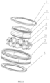
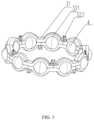
- the deep groove ball bearing comprises an outer ring 2, an inner ring 1, a retainer 3 and steel balls 4, wherein the retainer 3 is disposed between the outer ring 2 and the inner ring 1, sockets are disposed on the retainer 3, the steel balls 4 are disposed in the sockets, the retainer 3 is formed by two retainer bodies 31 which are separated from each other, grooves 321 are formed in the retainer bodies 31 at intervals, the grooves 321 in one retainer body 31 are combined with the grooves 321 in the other retainer body 31 to form the sockets, each of the retainer bodies 31 is provided with a plurality of sub-connectors 32 which are separated from each other, a first connecting block 324 and a second connecting block 325 are formed at two ends of each sub-connector 32 respectively, two grooves 321 are formed in each sub-connector 32, a positioning table 322 is disposed between the two grooves 321
- the retainer 3 can be divided into the retainer bodies 31, such that the steel balls can be mounted easily, the two retainer bodies 31 can be connected easily and efficiently through the connecting arms, and the structure is simple; each retainer body 31 is provided with a plurality of sub-connectors 32 which are separated from each other, and each sub-connector 32 comprises two grooves 321, such that the structure is uniform, and mass production can be realized; moreover, the adjacent sub-connectors 32 are connected through the connecting blocks, the connecting arms are disposed on the positioning tables 322, and the connecting arms are inserted into and matched with the connecting boards at corresponding positions to connect the retainer bodies, such that the connection correspondence is good, the overall stability of the retainer 3 is high, the retainer bodies 32 are unlikely to be separated from each other and can be changed easily after being damaged, assembly and production are easy, and the use effect of the whole structure is improved.
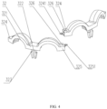
- the connecting arm comprises two elastic grippers 323, one end of each gripper is connected to the corresponding positioning table 322, the other end of each gripper is provided with a hook, and a contact surface between the hook and the corresponding connecting hole 326 is sloping.
- the connecting arm is simple in structure and has a good connecting effect; contact surface between the hook and the corresponding connecting hole 326 is sloping, such that a good guide effect can be realized in the insertion process, and the clamping effect is improved; moreover, the structure is simple and easy to realize.
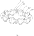
- a first insertion protrusion 3241 is formed on the first connecting block 324
- a second insertion protrusion 3251 is formed on the second connecting block 325
- the first insertion protrusion 3241 is staggered with the second insertion protrusion 3251
- a first insertion slot is formed in a position, corresponding to the second insertion protrusion 3251, of the first connecting block 324
- a second insertion slot is formed in a position, corresponding to the first insertion protrusion 3241, of the second connecting block 325
- the second insertion protrusion 3251 is inserted into and matched with the first insertion slot.
- connecting holes 326 are formed in the first connecting block 324 and the second connecting block 325 respectively and penetrate through the first insertion slot or the second insertion slot, and holes allowing the elastic grippers 323 to penetrate through are formed in the first insertion protrusion 3241 and the second insertion protrusion 3251.
- Such an arrangement has the following beneficial effects: the stability of the whole structure is further improved, after the first connecting blocks 324 and the second connecting blocks 325 are connected, that is, the retainer bodies 31 are assembled, the elastic grippers 323 can penetrate through the insertion protrusions when the connecting arms are inserted to connect the two retainer bodies 31, such that the retainer bodies 31 can be connected more tightly and are unlikely to be separated from each other, the use stability of the whole structure is improved, and the use effect is improved.
- the deep groove ball bearing comprises an outer ring 2, an inner ring 1, a retainer 3 and steel balls 4, wherein the retainer 3 is disposed between the outer ring 2 and the inner ring 1, sockets are disposed on the retainer 3, the steel balls 4 are disposed in the sockets, the retainer 3 is formed by two retainer bodies 31 which are separated from each other, grooves 321 are formed in the retainer bodies 31 at intervals, the grooves 321 in one retainer body 31 are combined with the grooves 321 in the other retainer body 31 to form the sockets, each of the retainer bodies 31 is provided with a plurality of sub-connectors 32 which are separated from each other, a first connecting block 324 and a second connecting block 325 are formed at two ends of each sub-connector 32 respectively, two grooves 321 are formed in each sub-connector 32, a positioning table 322 is disposed between the two grooves 321 in each sub-connector
- the retainer 3 can be divided into the retainer bodies 31, such that the steel balls can be mounted easily, the two retainer bodies 31 can be connected easily and efficiently through the connecting arms, and the structure is simple; each retainer body 31 is provided with a plurality of sub-connectors 32 which are separated from each other, and each sub-connector 32 comprises two grooves 321, such that the structure is uniform, and mass production can be realized; moreover, the adjacent sub-connectors 32 are connected through the connecting blocks, the connecting arms are disposed on the positioning tables 322, and the connecting arms are inserted into and matched with the connecting boards at corresponding positions to connect the retainer bodies, such that the connection correspondence is good, the overall stability of the retainer 3 is high, the retainer bodies 32 are unlikely to be separated from each other and can be changed easily after being damaged, assembly and production are easy, and the use effect of the whole structure is improved.
- the connecting arm comprises two elastic grippers 323, one end of each gripper is connected to the corresponding positioning table 322, the other end of each gripper is provided with a hook, and a contact surface between the hook and the corresponding connecting hole 326 is sloping.
- the connecting arm is simple in structure and has a good connecting effect; contact surface between the hook and the corresponding connecting hole 326 is sloping, such that a good guide effect can be realized in the insertion process, and the clamping effect is improved; moreover, the structure is simple and easy to realize.
- a first insertion protrusion 3241 is formed on the first connecting block 324
- a second insertion protrusion 3251 is formed on the second connecting block 325
- the first insertion protrusion 3241 is staggered with the second insertion protrusion 3251
- a first insertion slot is formed in a position, corresponding to the second insertion protrusion 3251, of the first connecting block 324
- a second insertion slot is formed in a position, corresponding to the first insertion protrusion 3241, of the second connecting block 325
- the second insertion protrusion 3251 is inserted into and matched with the first insertion slot.
- connecting holes 326 are formed in the first connecting block 324 and the second connecting block 325 respectively and penetrate through the first insertion slot or the second insertion slot, and holes allowing the elastic grippers 323 to penetrate through are formed in the first insertion protrusion 3241 and the second insertion protrusion 3251.
- Such an arrangement has the following beneficial effects: the stability of the whole structure is further improved, after the first connecting blocks 324 and the second connecting blocks 325 are connected, that is, the retainer bodies 31 are assembled, the elastic grippers 323 can penetrate through the insertion protrusions when the connecting arms are inserted to connect the two retainer bodies 31, such that the retainer bodies 31 can be connected more tightly and are unlikely to be separated from each other, the use stability of the whole structure is improved, and the use effect is improved.
- a first connecting step is formed on an inner wall of the outer ring 2
- a second connecting step 11 is formed on an outer wall of the inner ring 1
- a dust cover 5 is clamped between the first connecting step and the second connecting step 11.
- the deep groove ball bearing comprises an outer ring 2, an inner ring 1, a retainer 3 and steel balls 4, wherein the retainer 3 is disposed between the outer ring 2 and the inner ring 1, sockets are disposed on the retainer 3, the steel balls 4 are disposed in the sockets, the retainer 3 is formed by two retainer bodies 31 which are separated from each other, grooves 321 are formed in the retainer bodies 31 at intervals, the grooves 321 in one retainer body 31 are combined with the grooves 321 in the other retainer body 31 to form the sockets, each of the retainer bodies 31 is provided with a plurality of sub-connectors 32 which are separated from each other, a first connecting block 324 and a second connecting block 325 are formed at two ends of each sub-connector 32, two grooves 321 are formed in each sub-connector 32, a positioning table 322 is disposed between the two grooves 321 in each
- the retainer 3 can be divided into the retainer bodies 31, such that the steel balls can be mounted easily, the two retainer bodies 31 can be connected easily and efficiently through the connecting arms, and the structure is simple; each retainer body 31 is provided with a plurality of sub-connectors 32 which are separated from each other, and each sub-connector 32 comprises two grooves 321, such that the structure is uniform, and mass production can be realized; moreover, the adjacent sub-connectors 32 are connected through the connecting blocks, the connecting arms are disposed on the positioning tables 322, and the connecting arms are inserted into and matched with the connecting boards at corresponding positions to connect the retainer bodies, such that the connection correspondence is good, the overall stability of the retainer 3 is high, the retainer bodies 32 are unlikely to be separated from each other and can be changed easily after being damaged, assembly and production are easy, and the use effect of the whole structure is improved.
- the connecting arm comprises two elastic grippers 323, one end of each gripper is connected to the corresponding positioning table 322, the other end of each gripper is provided with a hook, and a contact surface between the hook and the corresponding connecting hole 326 is sloping.
- the connecting arm is simple in structure and has a good connecting effect; contact surface between the hook and the corresponding connecting hole 326 is sloping, such that a good guide effect can be realized in the insertion process, and the clamping effect is improved; moreover, the structure is simple and easy to realize.
- a first insertion protrusion 3241 is formed on the first connecting block 324
- a second insertion protrusion 3251 is formed on the second connecting block 325
- the first insertion protrusion 3241 is staggered with the second insertion protrusion 3251
- a first insertion slot is formed in a position, corresponding to the second insertion protrusion 3251, of the first connecting block 324
- a second insertion slot is formed in a position, corresponding to the first insertion protrusion 3241, of the second connecting block 325
- the second insertion protrusion 3251 is inserted into and matched with the first insertion slot.
- connecting holes 326 are formed in the first connecting block 324 and the second connecting block 325 respectively and penetrate through the first insertion slot or the second insertion slot, and holes allowing the elastic grippers 323 to penetrate through are formed in the first insertion protrusion 3241 and the second insertion protrusion 3251.
- Such an arrangement has the following beneficial effects: the stability of the whole structure is further improved, after the first connecting blocks 324 and the second connecting blocks 325 are connected, that is, the retainer bodies 31 are assembled, the elastic grippers 323 can penetrate through the insertion protrusions when the connecting arms are inserted to connect the two retainer bodies 31, such that the retainer bodies 31 can be connected more tightly and are unlikely to be separated from each other, the use stability of the whole structure is improved, and the use effect is improved.
- abutting steps 3242 are formed between the first connecting block 324 and the sub-connector 32, as well as between the second connecting block 325 and the sub-connector 32 respectively, and the positioning table 322 is formed with an abutting stage 3221 and is clamped with the abutting steps 3242 through the abutting stage 3221.
- Such an arrangement has the following beneficial effects: the abutting steps abut against the positioning table 322, such that when the retainer 3 is used, the stability of the whole structure can be improved, the situation where the whole structure becomes loose due to collisions of the steel balls 4 is avoided, the use effect of the whole structure is improved, the structure is simple and easy to realize, the service life is effectively prolonged, and mounting and positioning are efficient, and the production and machining efficiency is improved.
- the deep groove ball bearing comprises an outer ring 2, an inner ring 1, a retainer 3 and steel balls 4, wherein the retainer 3 is disposed between the outer ring 2 and the inner ring 1, sockets are disposed on the retainer 3, the steel balls 4 are disposed in the sockets, the retainer 3 is formed by two retainer bodies 31 which are separated from each other, grooves 321 are formed in the retainer bodies 31 at intervals, the grooves 321 in one retainer body 31 are combined with the grooves 321 in the other retainer body 31 to form the sockets, each of the retainer bodies 31 is provided with a plurality of sub-connectors 32 which are separated from each other, a first connecting block 324 and a second connecting block 325 are formed at two ends of each sub-connector 32, two grooves 321 are formed in each sub-connector 32, a positioning table 322 is disposed between the two grooves 321 in each
- the retainer 3 can be divided into the retainer bodies 31, such that the steel balls can be mounted easily, the two retainer bodies 31 can be connected easily and efficiently through the connecting arms, and the structure is simple; each retainer body 31 is provided with a plurality of sub-connectors 32 which are separated from each other, and each sub-connector 32 comprises two grooves 321, such that the structure is uniform, and mass production can be realized; moreover, the adjacent sub-connectors 32 are connected through the connecting blocks, the connecting arms are disposed on the positioning tables 322, and the connecting arms are inserted into and matched with the connecting boards at corresponding positions to connect the retainer bodies, such that the connection correspondence is good, the overall stability of the retainer 3 is high, the retainer bodies 32 are unlikely to be separated from each other and can be changed easily after being damaged, assembly and production are easy, and the use effect of the whole structure is improved.
- the connecting arm comprises two elastic grippers 323, one end of each gripper is connected to the corresponding positioning table 322, the other end of each gripper is provided with a hook, and a contact surface between the hook and the corresponding connecting hole 326 is sloping.
- the connecting arm is simple in structure and has a good connecting effect; contact surface between the hook and the corresponding connecting hole 326 is sloping, such that a good guide effect can be realized in the insertion process, and the clamping effect is improved; moreover, the structure is simple and easy to realize.
- a first insertion protrusion 3241 is formed on the first connecting block 324
- a second insertion protrusion 3251 is formed on the second connecting block 325
- the first insertion protrusion 3241 is staggered with the second insertion protrusion 3251
- a first insertion slot is formed in a position, corresponding to the second insertion protrusion 3251, of the first connecting block 324
- a second insertion slot is formed in a position, corresponding to the first insertion protrusion 3241, of the second connecting block 325
- the second insertion protrusion 3251 is inserted into and matched with the first insertion slot.
- connecting holes 326 are formed in the first connecting block 324 and the second connecting block 325 respectively and penetrate through the first insertion slot or the second insertion slot, and holes allowing the elastic grippers 323 to penetrate through are formed in the first insertion protrusion 3241 and the second insertion protrusion 3251.
- Such an arrangement has the following beneficial effects: the stability of the whole structure is further improved, after the first connecting blocks 324 and the second connecting blocks 325 are connected, that is, the retainer bodies 31 are assembled, the elastic grippers 323 can penetrate through the insertion protrusions when the connecting arms are inserted to connect the two retainer bodies 31, such that the retainer bodies 31 can be connected more tightly and are unlikely to be separated from each other, the use stability of the whole structure is improved, and the use effect is improved.
- abutting steps 3242 are formed between the first connecting block 324 and the sub-connector 32, as well as between the second connecting block 325 and the sub-connector 32 respectively, and the positioning table 322 is formed with an abutting stage 3221 and is clamped with the abutting steps 3242 through the abutting stage 3221.
- Such an arrangement has the following beneficial effects: the abutting steps abut against the positioning table 322, such that when the retainer 3 is used, the stability of the whole structure can be improved, the situation where the whole structure becomes loose due to collisions of the steel balls 4 is avoided, the use effect of the whole structure is improved, the structure is simple and easy to realize, the service life is effectively prolonged, and mounting and positioning are efficient, and the production and machining efficiency is improved.
- a first connecting step is formed on an inner wall of the outer ring 2
- a second connecting step 11 is formed on an outer wall of the inner ring 1
- a dust cover 5 is clamped between the first connecting step and the second connecting step 11.
- the deep groove ball bearing comprises an outer ring 2, an inner ring 1, a retainer 3 and steel balls 4, wherein the retainer 3 is disposed between the outer ring 2 and the inner ring 1, sockets are disposed on the retainer 3, the steel balls 4 are disposed in the sockets, the retainer 3 is formed by two retainer bodies 31 which are separated from each other, grooves 321 are formed in the retainer bodies 31 at intervals, the grooves 321 in one retainer body 31 are combined with the grooves 321 in the other retainer body 31 to form the sockets, each of the retainer bodies 31 is provided with a plurality of sub-connectors 32 which are separated from each other, a first connecting block 324 and a second connecting block 325 are formed at two ends of each sub-connector 32, two grooves 321 are formed in each sub-connector 32, a positioning table 322 is disposed between the two grooves 321 in each
- the retainer 3 can be divided into the retainer bodies 31, such that the steel balls can be mounted easily, the two retainer bodies 31 can be connected easily and efficiently through the connecting arms, and the structure is simple; each retainer body 31 is provided with a plurality of sub-connectors 32 which are separated from each other, and each sub-connector 32 comprises two grooves 321, such that the structure is uniform, and mass production can be realized; moreover, the adjacent sub-connectors 32 are connected through the connecting blocks, the connecting arms are disposed on the positioning tables 322, and the connecting arms are inserted into and matched with the connecting boards at corresponding positions to connect the retainer bodies, such that the connection correspondence is good, the overall stability of the retainer 3 is high, the retainer bodies 32 are unlikely to be separated from each other and can be changed easily after being damaged, assembly and production are easy, and the use effect of the whole structure is improved.
- the connecting arm comprises two elastic grippers 323, one end of each gripper is connected to the corresponding positioning table 322, the other end of each gripper is provided with a hook, and a contact surface between the hook and the corresponding connecting hole 326 is sloping.
- the connecting arm is simple in structure and has a good connecting effect; contact surface between the hook and the corresponding connecting hole 326 is sloping, such that a good guide effect can be realized in the insertion process, and the clamping effect is improved; moreover, the structure is simple and easy to realize.
- a first insertion protrusion 3241 is formed on the first connecting block 324
- a second insertion protrusion 3251 is formed on the second connecting block 325
- the first insertion protrusion 3241 is staggered with the second insertion protrusion 3251
- a first insertion slot is formed in a position, corresponding to the second insertion protrusion 3251, of the first connecting block 324
- a second insertion slot is formed in a position, corresponding to the first insertion protrusion 3241, of the second connecting block 325
- the second insertion protrusion 3251 is inserted into and matched with the first insertion slot.
- connecting holes 326 are formed in the first connecting block 324 and the second connecting block 325 respectively and penetrate through the first insertion slot or the second insertion slot, and holes allowing the elastic grippers 323 to penetrate through are formed in the first insertion protrusion 3241 and the second insertion protrusion 3251.
- Such an arrangement has the following beneficial effects: the stability of the whole structure is further improved, after the first connecting blocks 324 and the second connecting blocks 325 are connected, that is, the retainer bodies 31 are assembled, the elastic grippers 323 can penetrate through the insertion protrusions when the connecting arms are inserted to connect the two retainer bodies 31, such that the retainer bodies 31 can be connected more tightly and are unlikely to be separated from each other, the use stability of the whole structure is improved, and the use effect is improved.
- abutting steps 3242 are formed between the first connecting block 324 and the sub-connector 32, as well as between the second connecting block 325 and the sub-connector 32 respectively, and the positioning table 322 is formed with an abutting stage 3221 and is clamped with the abutting steps 3242 through the abutting stage 3221.
- Such an arrangement has the following beneficial effects: the abutting steps abut against the positioning table 322, such that when the retainer 3 is used, the stability of the whole structure can be improved, the situation where the whole structure becomes loose due to collisions of the steel balls 4 is avoided, the use effect of the whole structure is improved, the structure is simple and easy to realize, the service life is effectively prolonged, and mounting and positioning are efficient, and the production and machining efficiency is improved.
- a dust cover 5 is clamped between the outer ring 2 and the inner ring 1.
Landscapes
- Engineering & Computer Science (AREA)
- General Engineering & Computer Science (AREA)
- Mechanical Engineering (AREA)
- Rolling Contact Bearings (AREA)
Claims (3)
- Roulement à billes à gorge profonde, comprenant une bague externe (2), une bague interne (1), un dispositif de retenue (3) et des billes d'acier (4), le dispositif de retenue (3) étant disposé entre la bague externe (2) et la bague interne (1), des compartiments étant disposées sur le dispositif de retenue (3), et les billes d'acier (4) étant disposées dans les compartiments, caractérisé en ce que le dispositif de retenue (3) est formé par deux corps de retenue (31) qui sont séparés l'un de l'autre, des gorges (321) sont formées dans les corps de retenue (31) à des intervalles, les gorges (321) dans un corps de retenue (31) sont combinées avec les gorges (321) dans l'autre corps de retenue (31) pour former les compartiments, chaque corps de retenue (31) est pourvu d'une pluralité de sous-raccords (32) qui sont séparés les uns des autres, un premier bloc de liaison (324) et un deuxième bloc de liaison (325) sont formés au niveau de deux extrémités de chaque sous-raccord (32) respectivement, deux gorges (321) sont formées dans chaque sous-raccord (32), une table de positionnement (322) est disposée entre les deux gorges (321) dans chaque sous-raccord (32), le premier bloc de liaison (324) sur chaque sous-raccord (32) est inséré dans et mis en correspondance avec le deuxième bloc de liaison (325) dans le sous-raccord (32) adjacent pour former une plaque de liaison, un bras de connexion est disposé sur la table de positionnement (322), un trou de liaison (326) est formé dans la plaque de liaison, et le bras de liaison est inséré dans le trou de liaison (326) pour relier de manière fixe les deux corps de retenue (31), caractérisé en ce que
le bras de liaison comprend deux pinces élastiques (323) qui pénètrent respectivement à travers des trous de liaison (326) formés dans le premier bloc de liaison (324) et le deuxième bloc de liaison (325), chaque pince (323) a une extrémité reliée à la table de positionnement (322) correspondante ainsi qu'une extrémité pourvue d'un crochet, et une surface de contact entre le crochet et le trou de liaison (326) correspondant est incline, une première protubérance d'insertion (3241) est formée sur le premier bloc de liaison (324), une deuxième protubérance d'insertion (3251) est formée sur le deuxième bloc de liaison (325), la première protubérance d'insertion (3241) est décalée par rapport à la deuxième protubérance d'insertion (3251), une première fente d'insertion est formée dans une position, correspondant à la deuxième protubérance d'insertion (3251), du premier bloc de liaison (324), la deuxième protubérance d'insertion (3251) est insérée dans et mise en correspondance avec la première fente d'insertion, une deuxième fente d'insertion est formée dans une position, correspondant à la première protubérance d'insertion (3241), du deuxième bloc de liaison (325), la première protubérance d'insertion (3241) est insérée dans et mise en correspondance avec la deuxième fente d'insertion, les trous de liaison (326) pénètrent à travers la première fente d'insertion ou la deuxième fente d'insertion, et des trous permettant aux pinces élastiques (323) de pénétrer à travers sont formés dans la première protubérance d'insertion (3241) et la deuxième protubérance d'insertion (3251). - Roulement à billes à gorge profonde selon la revendication 1, caractérisé en ce que des saillies de butée (3242) sont formées entre le premier bloc de liaison (324) et le sous-raccord (32), ainsi qu'entre le deuxième bloc de liaison (325) et le sous-raccord (32) respectivement, et la table de positionnement (322) est formée avec un étage de butée (3221) et est serrée avec les saillies de butée (3242) à travers l'étage de butée (3221).
- Roulement à billes à gorge profonde selon la revendication 1, caractérisé en ce qu'une première saillie de liaison est formée sur une paroi interne de la bague externe (2), une deuxième saillie de liaison (11) est formée sur une paroi externe de la bague interne (1), et un couvercle anti-poussière (5) est serré entre la première saillie de liaison et la deuxième saillie de liaison (11).
Applications Claiming Priority (2)
| Application Number | Priority Date | Filing Date | Title |
|---|---|---|---|
| CN202110734599.1A CN113530978B (zh) | 2021-06-30 | 2021-06-30 | 深沟球轴承 |
| PCT/CN2021/118717 WO2023272952A1 (fr) | 2021-06-30 | 2021-09-16 | Roulement à billes à gorges profondes |
Publications (4)
| Publication Number | Publication Date |
|---|---|
| EP4332397A1 EP4332397A1 (fr) | 2024-03-06 |
| EP4332397A4 EP4332397A4 (fr) | 2024-07-31 |
| EP4332397C0 EP4332397C0 (fr) | 2025-02-26 |
| EP4332397B1 true EP4332397B1 (fr) | 2025-02-26 |
Family
ID=78126330
Family Applications (1)
| Application Number | Title | Priority Date | Filing Date |
|---|---|---|---|
| EP21947883.1A Active EP4332397B1 (fr) | 2021-06-30 | 2021-09-16 | Roulement à billes à gorges profondes |
Country Status (5)
| Country | Link |
|---|---|
| US (1) | US12078209B2 (fr) |
| EP (1) | EP4332397B1 (fr) |
| JP (1) | JP7530527B2 (fr) |
| CN (1) | CN113530978B (fr) |
| WO (1) | WO2023272952A1 (fr) |
Families Citing this family (1)
| Publication number | Priority date | Publication date | Assignee | Title |
|---|---|---|---|---|
| CN114688167A (zh) * | 2022-04-21 | 2022-07-01 | 人本股份有限公司 | 深沟球轴承保持架 |
Family Cites Families (34)
| Publication number | Priority date | Publication date | Assignee | Title |
|---|---|---|---|---|
| US1241669A (en) | 1917-04-28 | 1917-10-02 | Stefan Schneider | Ball-retainer. |
| US1966775A (en) * | 1930-03-08 | 1934-07-17 | Weis Richard | Cage for antifriction bearings |
| US2017772A (en) * | 1933-09-08 | 1935-10-15 | Schildgen Georg | Bearing cage |
| GB929032A (en) * | 1961-08-25 | 1963-06-19 | Robert Kling Wetzlar G M B H | Improvements in or relating to rectilinear roller bearings |
| DE3241215A1 (de) | 1982-11-08 | 1984-05-10 | FAG Kugelfischer Georg Schäfer KGaA, 8720 Schweinfurt | Segmentkaefig fuer radialrillenkugellager |
| IT1292868B1 (it) * | 1997-04-17 | 1999-02-11 | Lazzari Srl | Pattino di scorrimento a circolazione di sfere |
| JP2001227547A (ja) * | 2000-02-16 | 2001-08-24 | Ntn Corp | 固体潤滑剤充填型の転がり軸受及び円筒ころ軸受 |
| JP2003343574A (ja) * | 2002-05-31 | 2003-12-03 | Nsk Ltd | ころ軸受 |
| JP2004218745A (ja) * | 2003-01-15 | 2004-08-05 | Ntn Corp | 超薄肉形転がり軸受およびその保持器 |
| JP2007198583A (ja) | 2005-12-27 | 2007-08-09 | Nsk Ltd | 合成樹脂製玉軸受用保持器及び玉軸受 |
| JP2007247814A (ja) * | 2006-03-16 | 2007-09-27 | Nsk Ltd | 分割型転がり軸受 |
| DE102006034967A1 (de) * | 2006-07-28 | 2008-01-31 | Schaeffler Kg | Geteiltes Wälzlager |
| JP2011106605A (ja) | 2009-11-19 | 2011-06-02 | Ntn Corp | 転がり軸受およびその保持器 |
| DE102011003376B4 (de) * | 2011-01-31 | 2017-09-14 | Aktiebolaget Skf | Segmentkäfig |
| JP5876237B2 (ja) * | 2011-06-27 | 2016-03-02 | Ntn株式会社 | 玉軸受用の合成樹脂製保持器および玉軸受 |
| DE102011088642A1 (de) | 2011-12-15 | 2013-06-20 | Schaeffler Technologies AG & Co. KG | Kugellagerkäfig, sowie hiermit versehenes Rillenkugellager |
| CN203223480U (zh) * | 2013-05-08 | 2013-10-02 | 襄阳汽车轴承股份有限公司 | 保持架球兜带润滑孔及储脂槽的深沟球轴承 |
| US9121450B2 (en) * | 2013-06-24 | 2015-09-01 | Korea Institute Of Science And Technology | Cage for rolling bearing |
| JP6742068B2 (ja) * | 2014-11-04 | 2020-08-19 | Ntn株式会社 | 合成樹脂製保持器および玉軸受 |
| JP6488726B2 (ja) * | 2015-01-28 | 2019-03-27 | 株式会社ジェイテクト | 転がり軸受、及び、樹脂製保持器の製造方法 |
| CN204553567U (zh) * | 2015-04-10 | 2015-08-12 | 杭州人本电机轴承有限公司 | 高速深沟球轴承保持架 |
| KR101966194B1 (ko) * | 2016-02-15 | 2019-04-05 | 셰플러코리아(유) | 볼 베어링용 케이지 |
| JP6805529B2 (ja) * | 2016-04-11 | 2020-12-23 | 株式会社ジェイテクト | 転がり軸受 |
| JP6834199B2 (ja) * | 2016-07-05 | 2021-02-24 | 株式会社ジェイテクト | 転がり軸受 |
| US9945421B2 (en) | 2016-07-06 | 2018-04-17 | Regal Beloit America, Inc. | Bearing retainer, bearing and associated method |
| CN206754163U (zh) * | 2017-04-01 | 2017-12-15 | 慈溪超凡轴承科技有限公司 | 用于深沟球轴承的保持架及深沟球轴承 |
| CN206874663U (zh) * | 2017-05-06 | 2018-01-12 | 宁波宝弘轴承有限公司 | 一种便于安装的轴承 |
| JP2019019921A (ja) | 2017-07-19 | 2019-02-07 | 三菱自動車工業株式会社 | ベアリング装置 |
| DE102017212688A1 (de) * | 2017-07-24 | 2019-01-24 | Aktiebolaget Skf | Lagerkäfig, Radiallageranordnung mit einem solchen Käfig, insbesondere für eine Ausgleichswelle |
| DE202017107296U1 (de) | 2017-09-08 | 2018-12-12 | Liebherr-Components Biberach Gmbh | Wälzlager |
| KR20190129616A (ko) * | 2018-05-11 | 2019-11-20 | 주식회사 베어링아트 | 케이지 및 그 제조 방법 |
| CN209469714U (zh) | 2018-12-25 | 2019-10-08 | 人本集团有限公司 | 一种深沟球轴承保持架 |
| US11009074B1 (en) * | 2019-11-11 | 2021-05-18 | Aktiebolaget Skf | Lightweight bearing cage for turbine engines and method of forming a lightweight bearing cage |
| CN212131067U (zh) * | 2020-03-13 | 2020-12-11 | 台州英克尔传动轴有限公司 | 一种调心滚子轴承剖分式保持架 |
-
2021
- 2021-06-30 CN CN202110734599.1A patent/CN113530978B/zh active Active
- 2021-09-16 EP EP21947883.1A patent/EP4332397B1/fr active Active
- 2021-09-16 JP JP2023573550A patent/JP7530527B2/ja active Active
- 2021-09-16 US US18/284,309 patent/US12078209B2/en active Active
- 2021-09-16 WO PCT/CN2021/118717 patent/WO2023272952A1/fr not_active Ceased
Also Published As
| Publication number | Publication date |
|---|---|
| JP2024519182A (ja) | 2024-05-08 |
| JP7530527B2 (ja) | 2024-08-07 |
| CN113530978B (zh) | 2023-02-21 |
| CN113530978A (zh) | 2021-10-22 |
| US20240084852A1 (en) | 2024-03-14 |
| EP4332397A1 (fr) | 2024-03-06 |
| US12078209B2 (en) | 2024-09-03 |
| EP4332397A4 (fr) | 2024-07-31 |
| WO2023272952A1 (fr) | 2023-01-05 |
| EP4332397C0 (fr) | 2025-02-26 |
Similar Documents
| Publication | Publication Date | Title |
|---|---|---|
| JP7429312B2 (ja) | 保持器を備えた深溝玉軸受 | |
| EP4332397B1 (fr) | Roulement à billes à gorges profondes | |
| CN111946736B (zh) | 一种圆锥滚子轴承 | |
| CN210034164U (zh) | 一种滚珠轴承 | |
| CN217633480U (zh) | 一种圆锥滚子轴承冲压保持架 | |
| CN222046406U (zh) | 一种双列角接触球轴承 | |
| CN216009265U (zh) | 用于深沟球轴承的保持架 | |
| CN1296137A (zh) | 双锥对称圆锥滚动体及其在圆锥滚子轴承中的应用 | |
| CN206268296U (zh) | 一种轴承定位结构及轴承 | |
| CN213954300U (zh) | 一种电动汽车变速箱轴承 | |
| CN209881571U (zh) | 电机转子轴向定位结构及雨刮电机 | |
| CN211778514U (zh) | 一种滚动轴承 | |
| CN112576614A (zh) | 一种球轴承尼龙保持架 | |
| CN217713359U (zh) | 一种磁悬浮电机用径向保护轴承及保护轴承组 | |
| CN223964644U (zh) | 一种防松轴承 | |
| CN223434655U (zh) | 组合式离合器分离轴承 | |
| CN215567295U (zh) | 一种便于装配倒角的四列圆柱滚子轴承 | |
| CN221033645U (zh) | 一种轴承内圈及轴承 | |
| CN222277468U (zh) | 一种摆线针轮减速机用一体化行星架组件 | |
| CN223621823U (zh) | 一种弹性预压单滚珠的风扇结构 | |
| CN215949743U (zh) | 一种风电滑环稳定的主轴连接结构 | |
| CN217355438U (zh) | 旋转式滚珠花键轴 | |
| CN221900650U (zh) | 一种低噪音无刷电机 | |
| CN115387906B (zh) | 低进口轮毂比发动机的进气承力框架连接结构及装配方法 | |
| CN221054178U (zh) | 一种轴承 |
Legal Events
| Date | Code | Title | Description |
|---|---|---|---|
| STAA | Information on the status of an ep patent application or granted ep patent |
Free format text: STATUS: THE INTERNATIONAL PUBLICATION HAS BEEN MADE |
|
| PUAI | Public reference made under article 153(3) epc to a published international application that has entered the european phase |
Free format text: ORIGINAL CODE: 0009012 |
|
| STAA | Information on the status of an ep patent application or granted ep patent |
Free format text: STATUS: REQUEST FOR EXAMINATION WAS MADE |
|
| 17P | Request for examination filed |
Effective date: 20231129 |
|
| AK | Designated contracting states |
Kind code of ref document: A1 Designated state(s): AL AT BE BG CH CY CZ DE DK EE ES FI FR GB GR HR HU IE IS IT LI LT LU LV MC MK MT NL NO PL PT RO RS SE SI SK SM TR |
|
| A4 | Supplementary search report drawn up and despatched |
Effective date: 20240701 |
|
| RIC1 | Information provided on ipc code assigned before grant |
Ipc: F16C 43/06 20060101ALI20240625BHEP Ipc: F16C 19/16 20060101ALI20240625BHEP Ipc: F16C 19/06 20060101ALI20240625BHEP Ipc: F16C 33/78 20060101ALI20240625BHEP Ipc: F16C 33/58 20060101ALI20240625BHEP Ipc: F16C 33/38 20060101AFI20240625BHEP |
|
| DAV | Request for validation of the european patent (deleted) | ||
| DAX | Request for extension of the european patent (deleted) | ||
| GRAP | Despatch of communication of intention to grant a patent |
Free format text: ORIGINAL CODE: EPIDOSNIGR1 |
|
| STAA | Information on the status of an ep patent application or granted ep patent |
Free format text: STATUS: GRANT OF PATENT IS INTENDED |
|
| INTG | Intention to grant announced |
Effective date: 20241111 |
|
| GRAS | Grant fee paid |
Free format text: ORIGINAL CODE: EPIDOSNIGR3 |
|
| GRAA | (expected) grant |
Free format text: ORIGINAL CODE: 0009210 |
|
| STAA | Information on the status of an ep patent application or granted ep patent |
Free format text: STATUS: THE PATENT HAS BEEN GRANTED |
|
| AK | Designated contracting states |
Kind code of ref document: B1 Designated state(s): AL AT BE BG CH CY CZ DE DK EE ES FI FR GB GR HR HU IE IS IT LI LT LU LV MC MK MT NL NO PL PT RO RS SE SI SK SM TR |
|
| REG | Reference to a national code |
Ref country code: GB Ref legal event code: FG4D |
|
| REG | Reference to a national code |
Ref country code: CH Ref legal event code: EP |
|
| REG | Reference to a national code |
Ref country code: DE Ref legal event code: R096 Ref document number: 602021026963 Country of ref document: DE |
|
| REG | Reference to a national code |
Ref country code: IE Ref legal event code: FG4D |
|
| U01 | Request for unitary effect filed |
Effective date: 20250325 |
|
| U07 | Unitary effect registered |
Designated state(s): AT BE BG DE DK EE FI FR IT LT LU LV MT NL PT RO SE SI Effective date: 20250331 |
|
| PG25 | Lapsed in a contracting state [announced via postgrant information from national office to epo] |
Ref country code: RS Free format text: LAPSE BECAUSE OF FAILURE TO SUBMIT A TRANSLATION OF THE DESCRIPTION OR TO PAY THE FEE WITHIN THE PRESCRIBED TIME-LIMIT Effective date: 20250526 |
|
| PG25 | Lapsed in a contracting state [announced via postgrant information from national office to epo] |
Ref country code: PL Free format text: LAPSE BECAUSE OF FAILURE TO SUBMIT A TRANSLATION OF THE DESCRIPTION OR TO PAY THE FEE WITHIN THE PRESCRIBED TIME-LIMIT Effective date: 20250226 |
|
| PG25 | Lapsed in a contracting state [announced via postgrant information from national office to epo] |
Ref country code: ES Free format text: LAPSE BECAUSE OF FAILURE TO SUBMIT A TRANSLATION OF THE DESCRIPTION OR TO PAY THE FEE WITHIN THE PRESCRIBED TIME-LIMIT Effective date: 20250226 |
|
| PG25 | Lapsed in a contracting state [announced via postgrant information from national office to epo] |
Ref country code: IS Free format text: LAPSE BECAUSE OF FAILURE TO SUBMIT A TRANSLATION OF THE DESCRIPTION OR TO PAY THE FEE WITHIN THE PRESCRIBED TIME-LIMIT Effective date: 20250626 Ref country code: NO Free format text: LAPSE BECAUSE OF FAILURE TO SUBMIT A TRANSLATION OF THE DESCRIPTION OR TO PAY THE FEE WITHIN THE PRESCRIBED TIME-LIMIT Effective date: 20250526 |
|
| PG25 | Lapsed in a contracting state [announced via postgrant information from national office to epo] |
Ref country code: HR Free format text: LAPSE BECAUSE OF FAILURE TO SUBMIT A TRANSLATION OF THE DESCRIPTION OR TO PAY THE FEE WITHIN THE PRESCRIBED TIME-LIMIT Effective date: 20250226 |
|
| PG25 | Lapsed in a contracting state [announced via postgrant information from national office to epo] |
Ref country code: SM Free format text: LAPSE BECAUSE OF FAILURE TO SUBMIT A TRANSLATION OF THE DESCRIPTION OR TO PAY THE FEE WITHIN THE PRESCRIBED TIME-LIMIT Effective date: 20250226 |
|
| U20 | Renewal fee for the european patent with unitary effect paid |
Year of fee payment: 5 Effective date: 20250908 |
|
| PG25 | Lapsed in a contracting state [announced via postgrant information from national office to epo] |
Ref country code: CZ Free format text: LAPSE BECAUSE OF FAILURE TO SUBMIT A TRANSLATION OF THE DESCRIPTION OR TO PAY THE FEE WITHIN THE PRESCRIBED TIME-LIMIT Effective date: 20250226 |
|
| PG25 | Lapsed in a contracting state [announced via postgrant information from national office to epo] |
Ref country code: SK Free format text: LAPSE BECAUSE OF FAILURE TO SUBMIT A TRANSLATION OF THE DESCRIPTION OR TO PAY THE FEE WITHIN THE PRESCRIBED TIME-LIMIT Effective date: 20250226 |
|
| PLBE | No opposition filed within time limit |
Free format text: ORIGINAL CODE: 0009261 |
|
| STAA | Information on the status of an ep patent application or granted ep patent |
Free format text: STATUS: NO OPPOSITION FILED WITHIN TIME LIMIT |
|
| 26N | No opposition filed |
Effective date: 20251127 |