EP4332404A1 - Dispositif de frein - Google Patents
Dispositif de frein Download PDFInfo
- Publication number
- EP4332404A1 EP4332404A1 EP22800311.7A EP22800311A EP4332404A1 EP 4332404 A1 EP4332404 A1 EP 4332404A1 EP 22800311 A EP22800311 A EP 22800311A EP 4332404 A1 EP4332404 A1 EP 4332404A1
- Authority
- EP
- European Patent Office
- Prior art keywords
- disc
- brake
- lining
- casing
- brake device
- Prior art date
- Legal status (The legal status is an assumption and is not a legal conclusion. Google has not performed a legal analysis and makes no representation as to the accuracy of the status listed.)
- Granted
Links
Images





Classifications
-
- F—MECHANICAL ENGINEERING; LIGHTING; HEATING; WEAPONS; BLASTING
- F16—ENGINEERING ELEMENTS AND UNITS; GENERAL MEASURES FOR PRODUCING AND MAINTAINING EFFECTIVE FUNCTIONING OF MACHINES OR INSTALLATIONS; THERMAL INSULATION IN GENERAL
- F16D—COUPLINGS FOR TRANSMITTING ROTATION; CLUTCHES; BRAKES
- F16D55/00—Brakes with substantially-radial braking surfaces pressed together in axial direction, e.g. disc brakes
- F16D55/24—Brakes with substantially-radial braking surfaces pressed together in axial direction, e.g. disc brakes with a plurality of axially-movable discs, lamellae, or pads, pressed from one side towards an axially-located member
- F16D55/26—Brakes with substantially-radial braking surfaces pressed together in axial direction, e.g. disc brakes with a plurality of axially-movable discs, lamellae, or pads, pressed from one side towards an axially-located member without self-tightening action
- F16D55/28—Brakes with only one rotating disc
-
- F—MECHANICAL ENGINEERING; LIGHTING; HEATING; WEAPONS; BLASTING
- F16—ENGINEERING ELEMENTS AND UNITS; GENERAL MEASURES FOR PRODUCING AND MAINTAINING EFFECTIVE FUNCTIONING OF MACHINES OR INSTALLATIONS; THERMAL INSULATION IN GENERAL
- F16D—COUPLINGS FOR TRANSMITTING ROTATION; CLUTCHES; BRAKES
- F16D55/00—Brakes with substantially-radial braking surfaces pressed together in axial direction, e.g. disc brakes
- F16D55/24—Brakes with substantially-radial braking surfaces pressed together in axial direction, e.g. disc brakes with a plurality of axially-movable discs, lamellae, or pads, pressed from one side towards an axially-located member
- F16D55/26—Brakes with substantially-radial braking surfaces pressed together in axial direction, e.g. disc brakes with a plurality of axially-movable discs, lamellae, or pads, pressed from one side towards an axially-located member without self-tightening action
- F16D55/28—Brakes with only one rotating disc
- F16D55/32—Brakes with only one rotating disc actuated by a fluid-pressure device arranged in or on the brake
-
- F—MECHANICAL ENGINEERING; LIGHTING; HEATING; WEAPONS; BLASTING
- F16—ENGINEERING ELEMENTS AND UNITS; GENERAL MEASURES FOR PRODUCING AND MAINTAINING EFFECTIVE FUNCTIONING OF MACHINES OR INSTALLATIONS; THERMAL INSULATION IN GENERAL
- F16D—COUPLINGS FOR TRANSMITTING ROTATION; CLUTCHES; BRAKES
- F16D65/00—Parts or details
- F16D65/0031—Devices for retaining friction material debris, e.g. dust collectors or filters
-
- F—MECHANICAL ENGINEERING; LIGHTING; HEATING; WEAPONS; BLASTING
- F16—ENGINEERING ELEMENTS AND UNITS; GENERAL MEASURES FOR PRODUCING AND MAINTAINING EFFECTIVE FUNCTIONING OF MACHINES OR INSTALLATIONS; THERMAL INSULATION IN GENERAL
- F16D—COUPLINGS FOR TRANSMITTING ROTATION; CLUTCHES; BRAKES
- F16D65/00—Parts or details
- F16D65/14—Actuating mechanisms for brakes; Means for initiating operation at a predetermined position
- F16D65/16—Actuating mechanisms for brakes; Means for initiating operation at a predetermined position arranged in or on the brake
- F16D65/18—Actuating mechanisms for brakes; Means for initiating operation at a predetermined position arranged in or on the brake adapted for drawing members together, e.g. for disc brakes
-
- F—MECHANICAL ENGINEERING; LIGHTING; HEATING; WEAPONS; BLASTING
- F16—ENGINEERING ELEMENTS AND UNITS; GENERAL MEASURES FOR PRODUCING AND MAINTAINING EFFECTIVE FUNCTIONING OF MACHINES OR INSTALLATIONS; THERMAL INSULATION IN GENERAL
- F16D—COUPLINGS FOR TRANSMITTING ROTATION; CLUTCHES; BRAKES
- F16D65/00—Parts or details
- F16D65/14—Actuating mechanisms for brakes; Means for initiating operation at a predetermined position
- F16D65/16—Actuating mechanisms for brakes; Means for initiating operation at a predetermined position arranged in or on the brake
- F16D65/18—Actuating mechanisms for brakes; Means for initiating operation at a predetermined position arranged in or on the brake adapted for drawing members together, e.g. for disc brakes
- F16D65/186—Actuating mechanisms for brakes; Means for initiating operation at a predetermined position arranged in or on the brake adapted for drawing members together, e.g. for disc brakes with full-face force-applying member, e.g. annular
-
- F—MECHANICAL ENGINEERING; LIGHTING; HEATING; WEAPONS; BLASTING
- F16—ENGINEERING ELEMENTS AND UNITS; GENERAL MEASURES FOR PRODUCING AND MAINTAINING EFFECTIVE FUNCTIONING OF MACHINES OR INSTALLATIONS; THERMAL INSULATION IN GENERAL
- F16D—COUPLINGS FOR TRANSMITTING ROTATION; CLUTCHES; BRAKES
- F16D65/00—Parts or details
- F16D65/38—Slack adjusters
-
- F—MECHANICAL ENGINEERING; LIGHTING; HEATING; WEAPONS; BLASTING
- F16—ENGINEERING ELEMENTS AND UNITS; GENERAL MEASURES FOR PRODUCING AND MAINTAINING EFFECTIVE FUNCTIONING OF MACHINES OR INSTALLATIONS; THERMAL INSULATION IN GENERAL
- F16D—COUPLINGS FOR TRANSMITTING ROTATION; CLUTCHES; BRAKES
- F16D65/00—Parts or details
- F16D65/38—Slack adjusters
- F16D65/40—Slack adjusters mechanical
- F16D65/52—Slack adjusters mechanical self-acting in one direction for adjusting excessive play
- F16D65/54—Slack adjusters mechanical self-acting in one direction for adjusting excessive play by means of direct linear adjustment
-
- F—MECHANICAL ENGINEERING; LIGHTING; HEATING; WEAPONS; BLASTING
- F16—ENGINEERING ELEMENTS AND UNITS; GENERAL MEASURES FOR PRODUCING AND MAINTAINING EFFECTIVE FUNCTIONING OF MACHINES OR INSTALLATIONS; THERMAL INSULATION IN GENERAL
- F16D—COUPLINGS FOR TRANSMITTING ROTATION; CLUTCHES; BRAKES
- F16D65/00—Parts or details
- F16D65/38—Slack adjusters
- F16D65/40—Slack adjusters mechanical
- F16D65/52—Slack adjusters mechanical self-acting in one direction for adjusting excessive play
- F16D65/56—Slack adjusters mechanical self-acting in one direction for adjusting excessive play with screw-thread and nut
- F16D65/567—Slack adjusters mechanical self-acting in one direction for adjusting excessive play with screw-thread and nut for mounting on a disc brake
-
- F—MECHANICAL ENGINEERING; LIGHTING; HEATING; WEAPONS; BLASTING
- F16—ENGINEERING ELEMENTS AND UNITS; GENERAL MEASURES FOR PRODUCING AND MAINTAINING EFFECTIVE FUNCTIONING OF MACHINES OR INSTALLATIONS; THERMAL INSULATION IN GENERAL
- F16D—COUPLINGS FOR TRANSMITTING ROTATION; CLUTCHES; BRAKES
- F16D65/00—Parts or details
- F16D65/78—Features relating to cooling
- F16D65/84—Features relating to cooling for disc brakes
- F16D65/847—Features relating to cooling for disc brakes with open cooling system, e.g. cooled by air
-
- F—MECHANICAL ENGINEERING; LIGHTING; HEATING; WEAPONS; BLASTING
- F16—ENGINEERING ELEMENTS AND UNITS; GENERAL MEASURES FOR PRODUCING AND MAINTAINING EFFECTIVE FUNCTIONING OF MACHINES OR INSTALLATIONS; THERMAL INSULATION IN GENERAL
- F16D—COUPLINGS FOR TRANSMITTING ROTATION; CLUTCHES; BRAKES
- F16D65/00—Parts or details
- F16D65/38—Slack adjusters
- F16D2065/386—Slack adjusters driven electrically
-
- F—MECHANICAL ENGINEERING; LIGHTING; HEATING; WEAPONS; BLASTING
- F16—ENGINEERING ELEMENTS AND UNITS; GENERAL MEASURES FOR PRODUCING AND MAINTAINING EFFECTIVE FUNCTIONING OF MACHINES OR INSTALLATIONS; THERMAL INSULATION IN GENERAL
- F16D—COUPLINGS FOR TRANSMITTING ROTATION; CLUTCHES; BRAKES
- F16D2121/00—Type of actuator operation force
- F16D2121/02—Fluid pressure
- F16D2121/04—Fluid pressure acting on a piston-type actuator, e.g. for liquid pressure
-
- F—MECHANICAL ENGINEERING; LIGHTING; HEATING; WEAPONS; BLASTING
- F16—ENGINEERING ELEMENTS AND UNITS; GENERAL MEASURES FOR PRODUCING AND MAINTAINING EFFECTIVE FUNCTIONING OF MACHINES OR INSTALLATIONS; THERMAL INSULATION IN GENERAL
- F16D—COUPLINGS FOR TRANSMITTING ROTATION; CLUTCHES; BRAKES
- F16D2121/00—Type of actuator operation force
- F16D2121/18—Electric or magnetic
- F16D2121/24—Electric or magnetic using motors
-
- F—MECHANICAL ENGINEERING; LIGHTING; HEATING; WEAPONS; BLASTING
- F16—ENGINEERING ELEMENTS AND UNITS; GENERAL MEASURES FOR PRODUCING AND MAINTAINING EFFECTIVE FUNCTIONING OF MACHINES OR INSTALLATIONS; THERMAL INSULATION IN GENERAL
- F16D—COUPLINGS FOR TRANSMITTING ROTATION; CLUTCHES; BRAKES
- F16D2125/00—Components of actuators
- F16D2125/18—Mechanical mechanisms
- F16D2125/20—Mechanical mechanisms converting rotation to linear movement or vice versa
- F16D2125/34—Mechanical mechanisms converting rotation to linear movement or vice versa acting in the direction of the axis of rotation
- F16D2125/40—Screw-and-nut
Definitions
- the invention consists of a brake device that has a system that optimizes the braking capacity of a rotating means such as a shaft, especially based on the retraction capacity of the brake discs.
- a rotating means such as a shaft
- TTL Time to lock
- the invention has application in different industrial fields, mainly in the automotive industry, and in all those industries where braking devices act even though they are not related to automobiles, such as turbines or motors used for the generation of electrical energy, but it is especially suitable for vehicles powered by an electric motor.
- the most well-known braking system in the automotive sector is the brake disc braking system, wherein once the brake pedal is actuated, a hydraulic, pneumatic or electrical system is activated that moves brake pads towards a disc that rotates jointly with the wheels of the vehicle, such that, by means of friction between the brake pads and the disc, the braking of the wheels and consequently of the vehicle takes place.
- the brake disc In this braking system, the brake disc, as already stated, continuously and rotates jointly with the wheels of the vehicle while the pads are in a fixed position with respect to the wheel. By moving the pads axially towards the brake disc, until they make contact with the disc, and by continuing to exert pressure on it, a friction is generated that causes the braking of the disc and therefore the braking of the wheels of the vehicle, consequently causing overheating between the parts in contact.
- the brake disc Due to the fact that the brake disc is constantly rotating, the only cooling that is obtained is due to the flow of air it receives from natural convection. Likewise, given the surface, material and configuration of the brake pads, it is extremely complex to have a cooling system therein which evacuates the heat generated.
- pads wear unevenly, causing offsets and eccentricities in said pads that affect braking, so the useful life of both the pads and the brake discs is limited.
- Document ES2705358 describes a brake device that defines an axial displacement of the brake discs, while a lining disc rotates jointly with the shaft, as it is mounted on same.
- said brake discs can be cooled by means of a fluid that flows through internal cavities, improving the operation of the device by reducing the heating capacity.
- Document ES2705358 also describes a braking device that is specially adapted to allow internal cooling, by means of fluid, of the brake discs, which can only move axially, while a lining disc transmits the rotation of the shaft.
- This document focuses on the methods of axial displacement of the mobile elements of the device, such as brake discs and lining discs.
- a retraction system which consists of a displacement of the brake discs with respect to the lining discs that is sufficient for said lining disc to be able rotate without friction of any kind, and therefore, allowing to reduce to a minimum the necessary distance to axially move said brake discs in the braking direction until achieving the necessary contact to brake.
- none of the devices described in the documents includes any technical feature that allows there to be provided an approximation system, which positions the brake discs at a minimum distance from the lining disc, without residual friction between them, allowing the braking propagation speed to increase and the braking time to be as short as possible, throughout the entire brake pad wear stroke.
- the devices described in the aforementioned documents require compression springs located between the lining discs and the brake discs, to separate the contact areas of said discs, thus including an element susceptible to damage and/or corrosion, due to the continuous stress to which it is subjected.
- the present invention relates to a brake device attachable (or that can be assembled) on a rotating shaft, that is, a torque transmitting shaft, in such a way that it can be assembled on the brake device directly or through intermediate elements such as a bushing.
- This brake device is specially adapted to be installed in vehicles that have an electric drive motor or a hybrid drive system, since, in vehicles of this type, the energy efficiency of all the systems incorporated in its architecture becomes much more relevant in order to maximize the electrical energy offered by current batteries, so that they weigh less and offer greater vehicle autonomy.
- electric and hybrid vehicles have energy recovery systems that are capable of generating braking torques of up to [0.2 g-0.3 g], cooperating with the mechanical brake system to reach 1 g of emergency deceleration braking, so that the mechanical system is actuated by EHB (Electronic Hydraulic Brake) or 100% electric systems.
- EHB Electro Hydraulic Brake
- This brake device substantially improves braking, achieving less wear thanks to its optimization with this approximation system, as in its free rotation, without energy loss due to residual friction, also requiring less energy for its application as it is closer together, and all of this increases vehicle autonomy.
- the device comprises:
- the fact that the support disc is coupled to the transmitting guide or guides in a floating manner means that, although said disc rotates with the shaft if it is mounted on or coupled to same, the support disc can move in the axial direction of the shaft even if the shaft does not move, since, for example, it can have a loose coupling.
- the second brake disc can be mounted in the same way as the first brake disc, that is, it can move axially with respect to the shaft, but it can also remain motionless for the device to work, without requiring the loose coupling.
- the first pusher element and the first brake disc are fixed, forming an axial displacement unit, that is, whenever they move, they do so together as a single element.
- the brake device may comprise compression springs located between the brake discs, so that, regardless of the displacement of the first pusher element, said first brake disc is always in contact with the first pusher element.
- said elements can be fixed in another way, such as by means of mechanical elements such as pins, even forming a single casting.
- the first casing comprises a drive system configured to, when activated, move the first pusher element, in the axial direction, towards the brake disc, pushing the first brake disc towards the first brake lining of said brake disc, generating a first friction, in such a way that in said displacement, the first brake disc is configured to exert a pushing pressure on the first lining of the lining disc, in the axial direction, and to move it towards the second brake disc, when it is pushed by the first pusher element.
- the second brake disc can remain immobile, acting as a stop for the axial displacement of the first pusher element, thus allowing the lining disc to contact each brake disc on both sides, compressing the linings, generating a braking torque, which is transmitted from the brake discs to the shaft.
- the second brake disc does not need to move axially to brake the lining disc and can be rigidly attached to the first casing, although it is also preferably fixed in a floating manner.
- the drive system when activated, can move the brake disc in the pushing direction, towards the second brake disc, it is also configured to, when deactivated, retract the first pusher element, moving said first pusher element, in an opposite direction to the direction of pushing on the first brake disc, in the axial direction.
- the first brake disc is also configured to move in an opposite direction to the direction of pushing on the lining disc, in the axial direction, jointly with the retraction, in said opposite direction, of the first pusher element.
- the retraction consists of a minimum displacement of the first pusher element in the opposite direction to the pushing displacement, so that said displacement is also carried out by the first brake disc, by forming an axial displacement unit. With this small displacement, a small axial clearance space is generated between the two brake discs, where the lining disc is located.
- the floating coupling of the lining disc on the transmitting guide together with the rotation of said lining disc, as it is coupled to the rotating shaft, are configured to place said lining disc between the two brake discs, within the axial clearance generated, being self-positioned, when the first brake disc moves in the opposite direction. In other words, it does not require springs between the support disc and the brake discs for them to separate, with the attachment of the lining disc to the transmitting guide being sufficient.
- the retraction only moves the first brake disc enough so that the lining disc can rotate without any type of residual friction with the brake discs. Therefore, the block time for a new braking is reduced to a minimum, since the travel of the first brake disc in a new braking would also be minimal.
- this configuration also allows to always adjust the separation distance of the brake discs to the lining disc when the linings are worn.
- the brake discs are always located at a minimum distance from the linings, and this distance is determined according to the elements that make up the drive system, solving the problems present in the devices described in the background.
- the lining disc thanks to the free rotation of the lining disc (without being subjected to axial force by the brake discs through springs) and its floating position with respect to the guiding support, the lining disc produces a very small lateral eccentricity, sufficient to move apart, and be moved apart, on each side of the brake discs until inertia self-positions it in the center. It is clear that the minuscule space generated by retraction of the pusher is sufficient for the "self-fitting" to occur and to free the lining from any friction and to free the rotating shaft from any residual brake.
- the brake device comprises:
- the operation of the device having a second casing would be the same as with the first casing, only that in this case, the second brake disc can move in the axial direction, towards the lining disc. In this way, faster braking could be produced by moving both brake discs towards the linings at the same time.
- the second brake disc is configured to exert a pushing pressure on the second lining in the axial direction, and to move said brake disc towards the first brake disc, when it is pushed by the second pusher element.
- the drive system of the second casing is configured to, when deactivated, retract the second pusher element, said second pusher element moving in a direction opposite to the direction of pushing on the second disc brake, in the axial direction.
- the second brake disc is configured to move in a direction opposite to the direction of pushing on the lining disc, in the axial direction, jointly with the retraction of the second pusher element, and the lining disc is configured to be self-positioned between the two brake discs, that is, to be separated from both, without generating residual friction, when the first and second pusher elements are retracted.
- the support disc of the lining disc comprises:
- the brake device comprises an elastic damping gasket located between each fitted coupling of each transmitting guide and the sliding connection housing of the lining disc.
- Said gasket allows the coupling between said parts to be more damped, avoiding vibrations and resonances that can damage the components of the device, canceling, in the same way, vibrations that can produce frequencies in the human hearing spectrum.
- said gasket is made of fluoropolymer rubber, which has a high chemical resistance, is highly resistant to abrasion and corrosion, and is able to withstand a continuous temperature of 200°-280°, with peaks of 340°, making it suitable for the described use.
- the lining disc comprises a plurality of fins, which allow the heat accumulated in the disc to be dissipated, arranged on a perimeter of a central through hole of the support disc, wherein:
- these fins When the lining disc rotates, due to its coupling to the rotating shaft, these fins rotate with the same angular velocity. In their rotation, the fins generate a drive of fluid, creating a current from the inside to the outside. Depending on the angle of inclination and surface of these fins, higher speed and fluid flow rate may be provided at the same rpm.
- the lining disc comprises a plurality of first linings and second linings, fixed, respectively, in an outer area of the first and second surfaces of the support disc, said linings being separated by radial channeled gaps; wherein the linings comprise a blade shape.
- the brake device comprises a particle filtering structure arranged concentrically covering the lining disc, configured to retain particles detached from the linings. In one embodiment, this structure is arranged between the first and second brake discs.
- the filtering structure is a cylindrical-shaped framework, arranged covering the first and second brake discs, that is, the area where friction is generated and particles are released from the linings to the outside.
- This framework can be fixed to the casing, as well as to any element that is not subject to displacement with respect to the shaft.
- At least one brake disc comprises an annulus shape, with a central disc through hole, concentric to the shaft, comprising the axial direction, and a solid outer friction section against linings.
- the area in which the friction of said brake disc is generated is solid so that it has a greater capacity to resist the stresses to which it is subjected.
- At least one brake disc comprises an annulus shape, with a central disc through hole, concentric to the shaft, that is, comprising the axial direction, and an outer friction section against linings comprising at least one internal channel configured for the passage of a fluid.
- said brake disc comprises a plurality of radially open internal channels through which a fluid, such as air, can pass in order to cool the brake disc, which is susceptible to heating up.
- At least one brake disc comprises a plurality of heat dissipation brake fins, wherein preferably, said brake fins are located on an outer perimeter of said brake disc, arranged in a radial direction.
- these heat dissipation fins can be part of the same casting body or of two or more rigidly attached independent bodies. In this way, if they are two bodies manufactured independently, the advantage is that the fins can be made of a material that has a better thermal conductivity so that it improves temperature dispersion (for example aluminum).
- the brake device comprises a bearing, preferably a roller bearing, which can be assembled on the shaft.
- This bearing allows the brake discs or the casing, which do not rotate on the shaft, to be supported, transmitting the transverse stresses of said components to the shaft.
- the brake device comprises at least one compression spring located between the brake discs, configured to exert a separation pressure between said brake discs. Said spring allows said brake discs to always be kept separated by a distance determined by the pusher element of the drive system.
- the brake device comprises at least one guide element, fixed to the first housing, oriented in the axial direction of the shaft; wherein the first brake disc comprises a through hole loosely fitted to said guide element; wherein the second brake disc comprises a through hole fitted to the guide element, which can also be loosely fitted, especially if the brake device comprises a second casing and a second pusher element.
- the brake device comprises an elastic damping gasket located between each fitting of each guide element and each through hole of the brake discs.
- This elastic gasket can be the same as the one located between the sliding connection housing of the lining disc and the transmitting guide.
- the brake device comprises a plurality of guide elements each comprising a guide screw inserted into a through hole, of the same plurality of through holes, of each of the brake discs, wherein said guide screws are configured to guide the displacement of the first brake disc in the axial direction of the shaft.
- Said guide screws are preferably inserted into the through holes located in lugs of each of the brake discs.
- the brake device comprises a plurality of compression springs, each one mounted concentrically on each guide screw, said compression springs being located between the first and second brake discs, said compression springs being configured to exert a separation pressure between said brake discs.
- the guide screws allow the distance between the first casing and the second brake disc, or between the two casings, to be limited, depending on the embodiment, as they can be threaded onto nuts that fix the components of the brake device.
- the pusher element of the axial drive system comprises:
- the axial drive system of the first pusher element comprises:
- the high pressure gasket is configured so that it deforms upon transverse contact with the surface of the piston when the piston moves in the pushing direction, undergoing an elastic deformation that allows storage of deformation energy, which performs the retraction displacement when the actuation system is deactivated.
- retraction depends directly on the properties and shape of the high pressure gasket, as well as on its deformation.
- the high pressure gasket is made of ethylene propylene diene rubber or EPDM, which consists of an elastomeric thermopolymer with high abrasion and wear resistance.
- the high pressure gasket is formed by two concentric gaskets facing each other in the cavity of the casing, each of which gaskets even more preferably has a U-shaped section.
- the brake device may comprise a thermal insulation part located between the piston and the first brake disc, or installed in the part of the brake disc wherein it is in contact with the piston.
- said insulating part allows thermal insulation of the piston, which is in contact with the fluid in the casing chamber, thus avoiding possible problems of said fluid boiling, which could cause a failure at the time of braking, known as the "Fading Effect".
- the piston comprises a cylindrical ring shape and the compression springs comprise a conical shape; or the piston comprises a conical ring shape and the compression springs comprise a cylindrical shape.
- the first solution is the combination of a cylindrical ring-shaped piston together with conical-shaped compression springs. These elements have a constant resistance force throughout the entire axial displacement stroke, so a balanced system is achieved.
- the second solution is the combination of a conical piston and some springs that comprise a cylindrical shape, these two elements having a linearly increasing resistance force along the length their stroke, so the system is balanced by equalizing the slope of the resistance force of each element. Both solutions guarantee permanent contact throughout the entire stroke of the pusher element and the first brake disc.
- the axial drive system comprises:
- This configuration allows precise adjustment of the retraction based on the distance traveled by the first pusher element, turning the motor in the direction opposite to the pushing displacement, only as much as is needed to leave enough clearance between the two brake discs so that the linings on the lining disc do not rub against any of them.
- this configuration also allows for a built-in auxiliary (hand) brake. This is because by rotating the piston with a desired torque, an axial force can be generated which, thanks to the resistance force of the thread of the piston with the cavity of the casing, it allows the mechanical load torque to be maintained constant, even though it does not have torque from the electric motor.
- the brake device may comprise:
- the axial drive system of the pusher element comprises:
- the brake device comprises a turbofan skeleton comprising a hollow cylindrical shape and a plurality of blades, separated by cavities, said blades arranged on a lateral surface of the turbofan, wherein said turbofan is arranged concentrically surrounding the brake discs and the lining disc, it is connected to the rotating shaft, and it is configured to rotate about itself, with respect to the first housing, generating forced ventilation in the brake device.
- This turbofan skeleton could also be suitable for use in other brake devices that do not have to comprise all the essential features of the device described above, since it can provide ventilation that cools the components that are likely to heat up due to friction.
- the invention consists of a brake device in which the element that rotates jointly with the shaft to brake (as it is configured to be coupled to same) is the lining disc (5), while the first brake disc (6) and the second brake disc (7), which are located on both sides of the lining disc (5), do not comprise rotation jointly with the shaft, as is common in most of the existing braking systems on the market, but instead have a floating connection with respect to the shaft, which allows axial displacement thereof.
- Figures 1A-1D show a perspective view of different embodiments that the first brake disc (6) and the second brake disc (7) may have, in such a way that all the figures show an annulus-shaped brake disc (6, 7), comprising an outer friction zone or section (61, 71) that can be solid, as shown in Figures 1A and 1C , or comprise a plurality of internal channels (62, 72) that are open and arranged radially, as shown in Figure 1B and 1D .
- Figures 1C and 1D show that the brake discs (6, 7) can comprise a plurality of fins, called brake fins (63, 73) as they are located on the brake disc (6, 7), and these fins can be part of the same casting as the rest of the disc or can be fixed by mechanical means such as screws, pins, or welding.
- These brake discs (6, 7) also have four fixing lugs, evenly distributed on the outer perimeter, each comprising a first brake disc through hole (64) and second brake disc through hole (74), said hole having an axial direction.
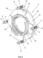
- FIG 2 it can be seen what the connection of a first brake disc (6) with a lining disc (5) would be.
- Said lining disc (5) is located between the two brake discs (6, 7), and like these, it comprises a circular through hole in the center, which allows placement of the shaft or bushing (20) to which it can be connected.
- the lining disc (5) shown in Figure 2 comprises a support disc (51) comprising an outer area, wherein, on the first and second surfaces of said support disc (51), four first linings (52) and four second linings (53) are fixed rigidly and respectively, being evenly distributed, so that the first four linings (52) are in contact with the first brake disc (6).
- the lining disc (5) comprises three evenly distributed pass-through sliding connection housings (54), wherein said three connection housings (54) comprise an axial direction and being configured to be assembled tightly or loosely, respectively, with three transmitting guides (2) of the guiding support (1).
- an elastic damping gasket (8) is located between each fitting of said sliding connection housings (54) with the transmitting guides (2).
- the lining disc (5) comprises a plurality of heat dissipation lining fins (55) located on the perimeter of the center circular through hole. These lining fins (55) act by not only dissipating the accumulated heat, since, when the lining disc (5) rotates, when coupled to the shaft, they generate a forced current that can ventilate the entire brake device.
- a channeled gap (56) which can be larger or smaller, depending on the size and number of linings included in the disc.
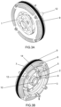
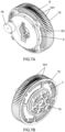
- Said channeled gaps (56) are specially designed to direct the particles generated in the wear of the linings (52, 53), due to friction with the brake discs (6, 7), radially outwards, wherein a filtering structure (9) can be located concentric to the lining disc (5), between the first brake disc (6) and the second brake disc (7), as shown in Figures 4 and 8 , or covering both brake discs (6, 7), as shown in Figures 5A and 5B .
- the operation of the brake device also requires a first casing (3) that can be rigidly connected to a frame, since it does not move with respect to the shaft, with said first casing (3) located next to the first disc (6), on the opposite side on which the lining disc (5) is located, which, like the brake discs (6, 7) can be supported on a bearing (10) that can be connected to the shaft in order to be able to transmit the transverse loads; and a first pusher element (13, 17, 18) movable in the axial direction with respect to the first casing (3) by means of a drive system located between the first casing (3) and the first brake disc (6).
- This drive system of the device is configured to axially move, in a pushing direction towards the first linings (52), the first pusher element (13, 17, 18) which is always in contact with the first brake disc (6), moving it in said direction, contacting the first lining (52) of the lining disc (5).
- This pushing (5) also generates an axial displacement in said lining disc (5), as it is connected to the transmitting guides (2) in a floating manner, in the same direction, until the second linings (53) contact the second brake disc (7), so that the generated tightening of the linings (52, 53) with the brake discs (6, 7) causes friction that leads to the braking of the shaft.
- the brake discs (6, 7) are coupled through the through holes (64, 74) on guide elements (12), also arranged in the axial direction, to be able to move axially with respect to the shaft and the first casing ( 3) in a floating manner.
- These guide elements (12) each comprise a guide screw threaded to a nut, and in addition to fixing the axial travel of the brake discs (6, 7), they also allow the length of their displacement to be delimited from the head of said screw to the nut to which it is threaded.
- each guide element (12) with the through holes (64, 74) comprise an elastic damping gasket (8) that facilitates sliding, dampen the possible vibrations generated, and also prevent possible thermal expansion from being able to affect the operation of the device.
- the brake device comprises compression springs located on the guide elements (12), which generate a controlled compression stress aimed at separating said discs (6, 7) as much as possibly allowed by the screws, nuts and pusher element.
- the drive system is configured so that the displacement in the direction opposite to the pushing displacement by the first pusher element (13, 17, 18), when it is desired to stop exerting the brake, is the minimum necessary and sufficient to allow the rotation of the lining disc (5), jointly with the shaft, without residual friction with the brake discs (6, 7).
- the distance that the brake discs (6, 7) must travel again towards the brake linings (52, 53) to carry out a new braking is reduced to a minimum.
- the braking time known as "Time to lock" (TTL) is reduced since the displacement in the direction opposite to the pushing displacement consists of a retraction of the first pusher element (13, 17, 18).
- This configuration allows the braking time to be shorter, so that even when the linings (52, 53) are worn, the distance to be traveled by the brake discs (6, 7) is always the minimum, and this is due to the fact that the brake discs (6, 7) as well as lining disc (5) are mounted in a floating manner.
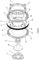
- the retraction of the first pusher element (13, 17, 18) generated by the drive system can be due to three embodiments shown in exploded views in Figures 4 , 6 and 8 .
- the first casing (3) comprises a cylindrical ring-shaped cavity in which a piston (13) is located.
- a fluid, liquid or gas is introduced into said cavity, axial displacement of said piston (13) (not visible in Figure 4 ) takes place, which moves the first brake disc (6) towards the lining disc (5), generating a first friction. Said displacement continues until moving the lining disc (5) against the second brake disc (7), wherein a tightening between the two linings (52, 53) with the two brake discs (6, 7) is generated.
- the fluid When it is desired to stop braking, the fluid is no longer introduced into the cavity of the first casing (3), and it is a high pressure gasket (15) that moves the retraction into said cavity.
- This high pressure gasket (15) is shown in Figure 9 and preferably consists of two gaskets or rubbers made of ethylene propylene diene or EPDM, with a U-shaped section, fixed to each side of the internal cavity, arranged concentrically to the piston.
- the displacement of the first pusher element (13, 17, 18) in the axial direction is no longer hydraulic or pneumatic, but electrical.
- the drive system comprises two electric motors (16) fixed to the first casing (3), each of which is connected by a thread configured to convert rotation into longitudinal displacement with an axially movable pusher (18), which can directly press the first brake disc (6) or a piston (13) located between them.
- these two electric motors (16) allow the first brake disc (6) to be moved in an aligned manner, as they are diametrically opposite one another, towards the lining disc (5) in the same way as with the fluid. To perform the retraction, it is enough for the electric motors (16) to move a minimum rotation in the direction opposite to the pushing direction to generate sufficient clearance between the brake discs (6, 7) and the lining disc (5) to that the latter can rotate without residual friction.
- the brake device comprises only one electric motor (16) that overcomes the possible misalignments or eccentricities of the first brake disc (6), in its axial displacement, with a geared system.
- said embodiment comprises a pinion (17) connected to a shaft of the electric motor (16), meshed with an inner toothing of the piston (13), which comprises a thread on an outer surface, threaded with a thread of the internal cavity of the first casing (3).
- the operation of this embodiment consists of the fact that the electric motor (16) rotates the pinion (17), which in turn transmits the rotational movement to the piston (13), transforming said rotation into an axial displacement.
- the electric motor (16) can axially move the piston (13) in any of the axial directions, either to perform the pushing that generates the braking or to carry out the retraction.
- This embodiment also shows a turbofan skeleton (19) that can be connected to the shaft through the bushing (20), which can rotate about itself, generating an current outside the brake discs (6, 7) and the lining disc (5) due to a plurality of blades (191) located on a cylindrical surface of said turbofan (19), which allows device components that are likely to overheat to be cooled, taking advantage of the rotation of the shaft.
Landscapes
- Engineering & Computer Science (AREA)
- General Engineering & Computer Science (AREA)
- Mechanical Engineering (AREA)
- Braking Arrangements (AREA)
- Braking Systems And Boosters (AREA)
Applications Claiming Priority (2)
| Application Number | Priority Date | Filing Date | Title |
|---|---|---|---|
| ES202130980A ES2886671A1 (es) | 2021-10-20 | 2021-10-20 | Dispositivo de freno |
| PCT/ES2022/070674 WO2023067230A1 (fr) | 2021-10-20 | 2022-10-20 | Dispositif de frein |
Publications (3)
| Publication Number | Publication Date |
|---|---|
| EP4332404A1 true EP4332404A1 (fr) | 2024-03-06 |
| EP4332404B1 EP4332404B1 (fr) | 2025-03-19 |
| EP4332404C0 EP4332404C0 (fr) | 2025-03-19 |
Family
ID=79023995
Family Applications (1)
| Application Number | Title | Priority Date | Filing Date |
|---|---|---|---|
| EP22800311.7A Active EP4332404B1 (fr) | 2021-10-20 | 2022-10-20 | Dispositif de frein |
Country Status (7)
| Country | Link |
|---|---|
| US (1) | US20250257771A1 (fr) |
| EP (1) | EP4332404B1 (fr) |
| JP (1) | JP2024539172A (fr) |
| KR (1) | KR20240089582A (fr) |
| CN (1) | CN118202166A (fr) |
| ES (2) | ES2886671A1 (fr) |
| WO (1) | WO2023067230A1 (fr) |
Families Citing this family (1)
| Publication number | Priority date | Publication date | Assignee | Title |
|---|---|---|---|---|
| ES2792148B2 (es) * | 2020-02-07 | 2021-10-18 | Brl Brake Solutions S L | Dispositivo de freno mejorado |
Family Cites Families (12)
| Publication number | Priority date | Publication date | Assignee | Title |
|---|---|---|---|---|
| US2105867A (en) * | 1936-05-25 | 1938-01-18 | Stewart Marvin | Brake |
| US2331259A (en) * | 1941-09-02 | 1943-10-05 | Kelsey Hayes Wheel Co | Brake construction |
| US3722637A (en) * | 1970-09-10 | 1973-03-27 | Lambert & Brake Corp | Self adjusting disc brake assembly |
| IT1019253B (it) * | 1974-07-10 | 1977-11-10 | Armco Steel Corp | Perfezionamento nei freni a disco in particolare per impiego su veicoli stradali |
| US4381049A (en) * | 1979-07-30 | 1983-04-26 | Goodyear Aerospace Corporation | Electrically actuated aircraft brakes |
| GB9116107D0 (en) * | 1991-07-25 | 1991-09-11 | Ti Interlock Ltd | Brake or clutch unit with wear adjustment device |
| US5307730A (en) * | 1992-11-13 | 1994-05-03 | General Motors Corporation | Piston return spring system with self-adjusting clearance feature |
| FR2820794A1 (fr) * | 2001-02-12 | 2002-08-16 | Messier Bugatti | Cinquieme frein de vehicule automobile |
| SE535405C2 (sv) * | 2011-01-11 | 2012-07-24 | Lars Landegren | Bromsanordning för ett fordon |
| ES2705358B2 (es) | 2017-09-22 | 2019-09-11 | Beneitez Jose Maria Gomez | Dispositivo de freno |
| CN110848293B (zh) * | 2019-11-08 | 2020-12-11 | 江苏科技大学 | 一种适用于跑车的快速冷却均温刹车盘 |
| ES2792148B2 (es) * | 2020-02-07 | 2021-10-18 | Brl Brake Solutions S L | Dispositivo de freno mejorado |
-
2021
- 2021-10-20 ES ES202130980A patent/ES2886671A1/es active Pending
-
2022
- 2022-10-20 WO PCT/ES2022/070674 patent/WO2023067230A1/fr not_active Ceased
- 2022-10-20 EP EP22800311.7A patent/EP4332404B1/fr active Active
- 2022-10-20 KR KR1020247015604A patent/KR20240089582A/ko active Pending
- 2022-10-20 CN CN202280070646.XA patent/CN118202166A/zh active Pending
- 2022-10-20 US US18/702,424 patent/US20250257771A1/en active Pending
- 2022-10-20 JP JP2024523723A patent/JP2024539172A/ja active Pending
- 2022-10-20 ES ES22800311T patent/ES3024239T3/es active Active
Also Published As
| Publication number | Publication date |
|---|---|
| WO2023067230A1 (fr) | 2023-04-27 |
| EP4332404B1 (fr) | 2025-03-19 |
| CN118202166A (zh) | 2024-06-14 |
| KR20240089582A (ko) | 2024-06-20 |
| ES2886671A1 (es) | 2021-12-20 |
| JP2024539172A (ja) | 2024-10-28 |
| ES3024239T3 (en) | 2025-06-04 |
| EP4332404C0 (fr) | 2025-03-19 |
| US20250257771A1 (en) | 2025-08-14 |
Similar Documents
| Publication | Publication Date | Title |
|---|---|---|
| EP2466164B1 (fr) | Frein de moteur d'actionneur de frein électromécanique | |
| KR101858285B1 (ko) | 향상된 피스톤을 갖는 전기기계식으로 작동가능한 차량 브레이크 | |
| EP2345830B1 (fr) | Actionneur linéaire électrique et dispositif de freinage électrique device | |
| EP2937599A1 (fr) | Mécanisme de rampe à billes, actionneur de mouvement linéaire et dispositif de frein à disque électrique | |
| EP3623274B1 (fr) | Frein de sécurité protégé multidisque à libération électromagnétique | |
| CN106164526A (zh) | 包括在双伺服模式下工作的驻车制动器的鼓式制动装置和相关联的车辆以及组装方法 | |
| CN110242689B (zh) | 一种双制动盘式制动器及汽车制动方法 | |
| CN108574371B (zh) | 具有集成式驻车制动器的电动机 | |
| CN111692244B (zh) | 一种重载电动车辆轮边动力及制动系统总成 | |
| EP4332404B1 (fr) | Dispositif de frein | |
| CN111098697A (zh) | 一种采用全盘式制动器的两级减速电动轮 | |
| CN110864079B (zh) | 一种平地机用蜗轮箱及平地机 | |
| US2375854A (en) | Heavy-duty disk brake | |
| CN114635934B (zh) | 一种飞机用碳/碳刹车装置 | |
| EP3045774B1 (fr) | Actionneur linéaire électrique et dispositif de freinage électrique | |
| CN114321225A (zh) | 一种制动装置、动力总成以及设备 | |
| EP4006375B1 (fr) | Capuchon de piston | |
| JP2022501554A (ja) | 電気駆動機械用のスリップクラッチ装置 | |
| CN110345182A (zh) | 一种应用于电动轮驱动车辆的驻车制动装置 | |
| CN119866288A (zh) | 机动车辆的制动装置及可电操作的车轴传动系 | |
| CN106564479A (zh) | 驱动桥及车辆 | |
| JP2024539172A5 (fr) | ||
| US12577993B2 (en) | Reduced profile piston adjuster | |
| CN223314992U (zh) | 制动装置、驱动桥及车辆 | |
| US20250297654A1 (en) | Electric disc brake actuator with vibration-damped differential reduction gear, components, brake and assembly method |
Legal Events
| Date | Code | Title | Description |
|---|---|---|---|
| STAA | Information on the status of an ep patent application or granted ep patent |
Free format text: STATUS: UNKNOWN |
|
| STAA | Information on the status of an ep patent application or granted ep patent |
Free format text: STATUS: THE INTERNATIONAL PUBLICATION HAS BEEN MADE |
|
| PUAI | Public reference made under article 153(3) epc to a published international application that has entered the european phase |
Free format text: ORIGINAL CODE: 0009012 |
|
| STAA | Information on the status of an ep patent application or granted ep patent |
Free format text: STATUS: REQUEST FOR EXAMINATION WAS MADE |
|
| 17P | Request for examination filed |
Effective date: 20231130 |
|
| AK | Designated contracting states |
Kind code of ref document: A1 Designated state(s): AL AT BE BG CH CY CZ DE DK EE ES FI FR GB GR HR HU IE IS IT LI LT LU LV MC ME MK MT NL NO PL PT RO RS SE SI SK SM TR |
|
| GRAP | Despatch of communication of intention to grant a patent |
Free format text: ORIGINAL CODE: EPIDOSNIGR1 |
|
| STAA | Information on the status of an ep patent application or granted ep patent |
Free format text: STATUS: GRANT OF PATENT IS INTENDED |
|
| DAV | Request for validation of the european patent (deleted) | ||
| DAX | Request for extension of the european patent (deleted) | ||
| INTG | Intention to grant announced |
Effective date: 20241206 |
|
| GRAS | Grant fee paid |
Free format text: ORIGINAL CODE: EPIDOSNIGR3 |
|
| GRAA | (expected) grant |
Free format text: ORIGINAL CODE: 0009210 |
|
| STAA | Information on the status of an ep patent application or granted ep patent |
Free format text: STATUS: THE PATENT HAS BEEN GRANTED |
|
| AK | Designated contracting states |
Kind code of ref document: B1 Designated state(s): AL AT BE BG CH CY CZ DE DK EE ES FI FR GB GR HR HU IE IS IT LI LT LU LV MC ME MK MT NL NO PL PT RO RS SE SI SK SM TR |
|
| REG | Reference to a national code |
Ref country code: GB Ref legal event code: FG4D |
|
| REG | Reference to a national code |
Ref country code: CH Ref legal event code: EP |
|
| REG | Reference to a national code |
Ref country code: DE Ref legal event code: R096 Ref document number: 602022012060 Country of ref document: DE |
|
| REG | Reference to a national code |
Ref country code: IE Ref legal event code: FG4D |
|
| U01 | Request for unitary effect filed |
Effective date: 20250410 |
|
| U07 | Unitary effect registered |
Designated state(s): AT BE BG DE DK EE FI FR IT LT LU LV MT NL PT RO SE SI Effective date: 20250416 |
|
| REG | Reference to a national code |
Ref country code: ES Ref legal event code: FG2A Ref document number: 3024239 Country of ref document: ES Kind code of ref document: T3 Effective date: 20250604 |
|
| PG25 | Lapsed in a contracting state [announced via postgrant information from national office to epo] |
Ref country code: RS Free format text: LAPSE BECAUSE OF FAILURE TO SUBMIT A TRANSLATION OF THE DESCRIPTION OR TO PAY THE FEE WITHIN THE PRESCRIBED TIME-LIMIT Effective date: 20250619 |
|
| PG25 | Lapsed in a contracting state [announced via postgrant information from national office to epo] |
Ref country code: NO Free format text: LAPSE BECAUSE OF FAILURE TO SUBMIT A TRANSLATION OF THE DESCRIPTION OR TO PAY THE FEE WITHIN THE PRESCRIBED TIME-LIMIT Effective date: 20250619 |
|
| PG25 | Lapsed in a contracting state [announced via postgrant information from national office to epo] |
Ref country code: HR Free format text: LAPSE BECAUSE OF FAILURE TO SUBMIT A TRANSLATION OF THE DESCRIPTION OR TO PAY THE FEE WITHIN THE PRESCRIBED TIME-LIMIT Effective date: 20250319 |
|
| PG25 | Lapsed in a contracting state [announced via postgrant information from national office to epo] |
Ref country code: GR Free format text: LAPSE BECAUSE OF FAILURE TO SUBMIT A TRANSLATION OF THE DESCRIPTION OR TO PAY THE FEE WITHIN THE PRESCRIBED TIME-LIMIT Effective date: 20250620 |
|
| PG25 | Lapsed in a contracting state [announced via postgrant information from national office to epo] |
Ref country code: SM Free format text: LAPSE BECAUSE OF FAILURE TO SUBMIT A TRANSLATION OF THE DESCRIPTION OR TO PAY THE FEE WITHIN THE PRESCRIBED TIME-LIMIT Effective date: 20250319 |
|
| PG25 | Lapsed in a contracting state [announced via postgrant information from national office to epo] |
Ref country code: PL Free format text: LAPSE BECAUSE OF FAILURE TO SUBMIT A TRANSLATION OF THE DESCRIPTION OR TO PAY THE FEE WITHIN THE PRESCRIBED TIME-LIMIT Effective date: 20250319 |
|
| PG25 | Lapsed in a contracting state [announced via postgrant information from national office to epo] |
Ref country code: CZ Free format text: LAPSE BECAUSE OF FAILURE TO SUBMIT A TRANSLATION OF THE DESCRIPTION OR TO PAY THE FEE WITHIN THE PRESCRIBED TIME-LIMIT Effective date: 20250319 |
|
| PG25 | Lapsed in a contracting state [announced via postgrant information from national office to epo] |
Ref country code: SK Free format text: LAPSE BECAUSE OF FAILURE TO SUBMIT A TRANSLATION OF THE DESCRIPTION OR TO PAY THE FEE WITHIN THE PRESCRIBED TIME-LIMIT Effective date: 20250319 |
|
| PG25 | Lapsed in a contracting state [announced via postgrant information from national office to epo] |
Ref country code: IS Free format text: LAPSE BECAUSE OF FAILURE TO SUBMIT A TRANSLATION OF THE DESCRIPTION OR TO PAY THE FEE WITHIN THE PRESCRIBED TIME-LIMIT Effective date: 20250719 |
|
| U20 | Renewal fee for the european patent with unitary effect paid |
Year of fee payment: 4 Effective date: 20251007 |
|
| PLBE | No opposition filed within time limit |
Free format text: ORIGINAL CODE: 0009261 |
|
| STAA | Information on the status of an ep patent application or granted ep patent |
Free format text: STATUS: NO OPPOSITION FILED WITHIN TIME LIMIT |
|
| REG | Reference to a national code |
Ref country code: CH Ref legal event code: L10 Free format text: ST27 STATUS EVENT CODE: U-0-0-L10-L00 (AS PROVIDED BY THE NATIONAL OFFICE) Effective date: 20260128 |
|
| PGFP | Annual fee paid to national office [announced via postgrant information from national office to epo] |
Ref country code: ES Payment date: 20251103 Year of fee payment: 4 |
|
| 26N | No opposition filed |
Effective date: 20251222 |