EP4332407B1 - Machine d'usinage et procédé ainsi qu'installation de fabrication pour la fabrication de disques de frein revêtus - Google Patents
Machine d'usinage et procédé ainsi qu'installation de fabrication pour la fabrication de disques de frein revêtus Download PDFInfo
- Publication number
- EP4332407B1 EP4332407B1 EP23185287.2A EP23185287A EP4332407B1 EP 4332407 B1 EP4332407 B1 EP 4332407B1 EP 23185287 A EP23185287 A EP 23185287A EP 4332407 B1 EP4332407 B1 EP 4332407B1
- Authority
- EP
- European Patent Office
- Prior art keywords
- workpiece
- spindle
- coating
- processing
- station
- Prior art date
- Legal status (The legal status is an assumption and is not a legal conclusion. Google has not performed a legal analysis and makes no representation as to the accuracy of the status listed.)
- Active
Links
Images


Classifications
-
- F—MECHANICAL ENGINEERING; LIGHTING; HEATING; WEAPONS; BLASTING
- F16—ENGINEERING ELEMENTS AND UNITS; GENERAL MEASURES FOR PRODUCING AND MAINTAINING EFFECTIVE FUNCTIONING OF MACHINES OR INSTALLATIONS; THERMAL INSULATION IN GENERAL
- F16D—COUPLINGS FOR TRANSMITTING ROTATION; CLUTCHES; BRAKES
- F16D65/00—Parts or details
- F16D65/02—Braking members; Mounting thereof
- F16D65/12—Discs; Drums for disc brakes
- F16D65/127—Discs; Drums for disc brakes characterised by properties of the disc surface; Discs lined with friction material
-
- F—MECHANICAL ENGINEERING; LIGHTING; HEATING; WEAPONS; BLASTING
- F16—ENGINEERING ELEMENTS AND UNITS; GENERAL MEASURES FOR PRODUCING AND MAINTAINING EFFECTIVE FUNCTIONING OF MACHINES OR INSTALLATIONS; THERMAL INSULATION IN GENERAL
- F16D—COUPLINGS FOR TRANSMITTING ROTATION; CLUTCHES; BRAKES
- F16D2250/00—Manufacturing; Assembly
- F16D2250/0038—Surface treatment
- F16D2250/0046—Coating
-
- F—MECHANICAL ENGINEERING; LIGHTING; HEATING; WEAPONS; BLASTING
- F16—ENGINEERING ELEMENTS AND UNITS; GENERAL MEASURES FOR PRODUCING AND MAINTAINING EFFECTIVE FUNCTIONING OF MACHINES OR INSTALLATIONS; THERMAL INSULATION IN GENERAL
- F16D—COUPLINGS FOR TRANSMITTING ROTATION; CLUTCHES; BRAKES
- F16D2250/00—Manufacturing; Assembly
- F16D2250/0092—Tools or machines for producing linings
Definitions
- the invention relates to a processing machine for use in the production of a coated brake disc, a method for producing a coated brake disc and a production plant for producing a coated brake disc.
- a brake disc is the part of a disc brake that is connected to the wheel in a rotationally fixed manner and on which the brake pads attached to a brake calliper act to slow down a rotational movement.
- a brake disc is usually point-symmetrical or rotationally symmetrical to an axle center through which the axis of rotation of the brake disc runs.
- a brake disc has the actual braking surface or friction surface and an inner hub section with the offset axle attachment or hub. The braking surface describes a circular ring on the brake disc.
- Gray cast iron brake discs are now reaching their limits in terms of corrosion and wear behavior, among other things.
- brake discs made of ceramic materials are expensive and have so far only been available for high-priced vehicles.
- the manufacturing process comprises at least one coating operation for coating the metallic base body of a brake disc with at least one functional layer, which generally consists essentially of metal and can, for example, have a wear-reducing and/or corrosion-inhibiting function.
- a functional layer can comprise one or more layers of different properties. This is usually followed by further machining operations, in particular grinding operations, to prepare the surface of the functional layer so that it can serve as the friction surface of the brake disc.
- the WO 2021/122951 A1 discloses, for example, a device for coating brake disks, in particular by means of laser deposition welding.
- the device comprises a base with a housing that forms a work space, a workpiece carrier in the work space, the workpiece carrier being designed to receive a base body of a brake disk, a coating head that is designed to produce a coating on the base body, a handling device that generates relative movements between the workpiece carrier and the coating head, and a multi-stage suction device for extracting excess material from the work space.
- the coating of brake disks using laser deposition welding is described, in particular using high-performance laser deposition welding processes, such as the EHLA process.
- the system is intended to be suitable for mass production.
- EHLA Extreme High-Speed Laser Material Deposition
- the DE 10 2011 100 456 A1 discloses a corresponding laser deposition welding process which is designed to apply wear protection layers and/or corrosion protection layers to a base body with high deposition performance.
- the process uses powdered material which is fed to a component and is melted at a distance from the surface to be coated and bonded to the component using thermal energy which is generated and introduced by a laser.
- EP 3 789 511 A1 discloses a coating device for metallic coating of workpieces, in particular brake disks.
- the coating device has a housing which encloses a working space and a holding device for holding at least one workpiece in the working space.
- At least two application devices are arranged in the working space, which are designed for the simultaneous application and melting of metal powder.
- a brake disk with arranged on a horizontal axis of rotation and coated from both sides simultaneously. This is intended to enable efficient production.
- the DE 10 2020 007 581 A1 discloses a device for coating brake discs comprising at least one swivel table with driven workpiece supports for receiving the brake disc to be coated, at least one inductive heating device for preheating and/or heating the brake disc, at least one processing optics, at least one powder application nozzle, wherein at least one sensor system is provided for measuring the layer thickness, wherein the processing optics, the powder application nozzle and the sensor system for measuring the layer thickness can be driven simultaneously.
- the object of the invention is to provide a processing machine for use in the production of a coated brake disc, a method for producing a coated brake disc and a production plant for producing a coated brake disc, which enable the production of coated brake discs at moderate unit costs on an industrial scale.
- the invention provides a processing machine with the features of claim 1 that can be used in the production of a coated brake disc. Furthermore, a method for producing a coated brake disc with the features of claim 10 and a production system with the features of claim 14 are provided, which comprises at least one processing machine. Preferred developments are specified in the dependent claims. The wording of all claims is made part of the content of the description by reference.
- a coated brake disc has a base body which has a rotationally symmetrical mass distribution in relation to a rotation axis of the brake disc and comprises a central hub section and a circular ring-shaped brake section surrounding the hub section.
- the brake section has two axially opposite surfaces, each of which has a coating that is rotationally symmetrical in relation to the rotation axis, the free surface of which is designed as the friction surface of the brake disc.
- the desired macrostructure and microstructure of the free surface of the coating can be created, for example, by grinding the initially possibly rough, possibly grooved and/or wavy surface of the coating.
- the brake disc (uncoated or coated) is also referred to as "workpiece" in this application.
- a processing machine which has a transport system which has a movable spindle carrier unit which carries at least one workpiece spindle.
- a workpiece spindle is a functional unit or an assembly with several components with different functions.
- the workpiece spindle is mounted so as to be rotatable about a spindle rotation axis relative to the spindle carrier unit. It has a workpiece holding device which is designed such that a workpiece held on the workpiece holding device in the form of a brake disk or a base body of the brake disk is rotated about the spindle rotation axis when the workpiece spindle rotates.
- the workpiece In preparation for machining, the workpiece is secured to the workpiece holding device, e.g. by clamping.
- the brake discs are secured in such a way that the rotation axis of the brake disc is arranged as coaxially as possible to the spindle rotation axis.
- the workpiece is preferably secured in a phase in which the workpiece spindle is not rotating around the spindle rotation axis, but is at rest.
- the spindle carrier unit of the transport system is then moved to transport the workpiece held on the workpiece spindle to a processing position of a processing station.
- the location where the workpiece spindle is loaded with the workpiece is therefore located away from the location where the processing is carried out.
- the internal machine transfer is carried out by the transport system.
- a processing machine for carrying out the method accordingly has several, i.e. two or more, work stations arranged along a transport path and accessible by the workpiece spindle, which comprise a loading station and at least one processing station with at least one processing unit for processing at least one side of the workpiece.
- the workpiece is attached to the workpiece holding device of the workpiece spindle, which is then moved to the processing station together with the workpiece held thereon.
- a machining operation is carried out in which a section that is rotationally symmetrical to the spindle rotation axis and/or the workpiece rotation axis is machined on at least one side of the workpiece.
- the workpiece is rotated by rotating the Workpiece spindle rotates around the spindle rotation axis at a working speed.
- the machining unit then machines the rotating workpiece.
- working speed can describe a specific speed that should remain constant during the machining process within tolerances. However, the term “working speed” also includes a more or less extensive speed range that extends from a minimum to a maximum speed. The working speed can change within this range during machining, if necessary according to a temporal speed profile that can be specified by the control system. For example, the working speed can vary so that a relative speed between a locally acting machining tool and the surface remains the same in all radial positions.
- the rotating workpiece and the machining unit are moved relative to each other during workpiece rotation in order to achieve surface machining.
- This relative movement can be generated, for example, by moving a machining unit while the workpiece spindle with the workpiece held in it is not moved to another position during machining.
- the machining unit is not moved during machining while the workpiece spindle moves with the rotating workpiece carried by it.
- a combination with a moving machining unit and a workpiece spindle moving transversely to the spindle rotation axis is also possible. If a machining technology is used that acts simultaneously over the entire radial extent of the area to be machined, a relative movement provided in addition to the workpiece rotation can also be omitted.
- the processing includes the production of a rotationally symmetrical functional coating or a functional layer on at least one surface of the brake section.
- the method and the processing machine are then configured in such a way that they are suitable for producing a rotationally symmetrical functional layer on at least one surface of a workpiece.
- a "rotationally symmetrical functional layer” is a more or less thin layer of material with a specific technical function that is applied to the surface to be coated in such a way that the coating material is distributed essentially rotationally symmetrically to an axis of symmetry of the rotationally symmetrical functional layer.
- the functional layer is applied in a circular area around the axis of rotation of the brake disc in order to form the friction surface for the brake pads.
- the functional layer often has several layers with different functions, e.g. an adhesive layer and a wear layer applied on top of it. However, single-layer functional layers are also possible.
- processing is grinding a functional layer applied to the braking section in order to smooth its surface, which is usually too rough at first, and to reduce any existing waviness and/or thickness variations.
- the processing machine can therefore also be configured as a grinding machine.
- Processing can also consist of activating a surface for subsequent processing, e.g. by roughening it using a laser or mechanically, or in some other way. Processing can also include cleaning with or without cleaning aids.
- a workstation can also be designed as a measuring station, which usually does not change the workpiece and therefore does not represent any processing.
- the workpiece In a machining station, the workpiece is to rotate around the spindle rotation axis at a working speed by rotating the workpiece spindle. A machining unit then machines the rotating workpiece.
- the workpiece spindle is set into rotation at an increasing speed after the workpiece has been fastened to the workpiece holding device and before the machining position is reached, and that the workpiece held on the workpiece spindle is thereby already moved into the machining position in a rotating manner at an entry speed.
- the drive system and the control unit can be configured accordingly and are configured accordingly in an operating mode.
- the acceleration of the rotary movement can begin immediately after the workpiece is secured to the workpiece holding device, i.e. before the spindle carrier unit is set in motion to leave the loading station and transport the workpiece spindle to the machining station.
- This entry speed can be Essentially correspond to the working speed required for machining, so that machining can begin without delay as soon as the workpiece is in the machining position.
- the entry speed can also deviate from the working speed, e.g. be lower than the working speed, so that a further, short acceleration phase is required.
- this procedure can shift the unproductive downtime for accelerating the workpiece spindle from standstill to the working speed partially or completely to a phase before the start of the machining operation. Accordingly, the dwell time of the workpiece or the workpiece spindle carrying the workpiece in the machining station is reduced essentially to the time required for machining the rotating workpiece, possibly plus a very short period of time to change the speed from the entry speed to the working speed.
- the dwell time of a workpiece in a processing station can be significantly reduced because at least part of the acceleration phase for generating the working speed already takes place in advance outside the processing station.
- a further advantage is that more time is available for accelerating the workpiece spindle from standstill to the working speed. This means that workpieces with higher masses can also be gradually brought up to speed without overloading the drives and/or smaller and/or weaker and/or more economical spindle drives can be used.
- This acceleration of the rotary movement before reaching the machining station can be provided regardless of the type of arrangement of the spindle drive. It can be used to advantage, for example, in processing machines with "moving" spindle drives. The acceleration can also be provided in processing machines with at least one frame-fixed spindle drive according to a further development of the invention described below.
- Typical working speeds can be in the range of more than approx. 100 rpm, preferably in the range of 150 rpm to 600 rpm, for example in the range of 200 rpm to 500 rpm.
- lower speeds in the range of one or fewer workpiece revolutions per minute may be more advantageous, such as when grinding.
- the processing machine can be configured, for example, as a coating machine that is used in a coating process.
- some embodiments are designed for double-sided coating, wherein in a first coating operation a first rotationally symmetrical functional layer is applied to a surface region of a first side and in a second coating operation a second rotationally symmetrical functional layer is applied to a surface region of a second side.
- the first and second coating operations are carried out in overlapping time, i.e. in phases or completely simultaneously.
- the first and second coating operations are carried out one after the other.
- the workpiece is fastened to the workpiece holding device in a first orientation for the first coating operation, is released from the workpiece holding device after the first coating operation, is turned over from the first orientation into a second orientation and reattached to the workpiece holder in the second orientation.
- the second side can then be coated.
- turning is preferably used in combination with an arrangement of the workpiece in which the spindle rotation axis of the workpiece spindle is vertically oriented so that the surfaces to be coated lie substantially in a horizontal plane.
- the coating machine may have a single work station designed as a coating station. Even in the case of process variants in which the workpiece is turned between a first and a second coating operation, a single coating station may be sufficient, provided that the possibility is created to turn the workpiece after the first coating operation and then carry out the second coating operation.
- the coating station can have an integrated turning unit for this purpose.
- the coating machine is designed such that it has at least two, in particular exactly two, work stations arranged separately from one another, which are designed as coating stations.
- a coating machine designed for this purpose comprises several work stations arranged along the transport path of the transport system, which have, in this order, a loading station, a first coating station with at least one coating unit for coating a first side of the workpiece, a turning station for turning a workpiece held on a workpiece spindle and at least one second coating station for coating a second side of the workpiece.
- the process stages “coating the first side”, “turning”, “coating the second side” are thus spatially separated and approached one after the other by internal machine transfer or transport.
- the following steps can be carried out, for example: arranging the workpiece in a first orientation on the workpiece holding device of a workpiece spindle in a loading operation; Transporting the workpiece held on the workpiece spindle to a first coating station; producing a first rotationally symmetrical functional layer on a first side of the workpiece in the first coating operation, wherein the workpiece is rotated by means of a spindle drive by rotating the workpiece spindle about a rotation axis and coating material is applied by a coating unit to the surface of the first side to be coated; Transporting the workpiece held on the workpiece spindle to a turning station; Turning the workpiece from the first orientation to a second orientation in a turning operation; Transporting the turned workpiece held on the workpiece spindle to a second coating station; producing a second rotationally symmetrical functional layer on the second side of the workpiece in the second coating station, wherein the
- An unloading station separate from the loading station can be provided. This is useful, for example, if the transport system is designed for linear transport, i.e. for transport along a straight transport path. In preferred embodiments, however, a machine-internal transport system with a closed transport path is provided, so that the loading station also functions as an unloading station. This means that the machine can be loaded with uncoated workpieces and coated workpieces can be removed at the same transfer point. This makes it possible to create highly efficient coating machines with compact dimensions and a correspondingly small space requirement or footprint. In addition, linking several such coating machines with an external conveyor system makes it particularly easy.
- the transport system has a rotary table or turntable that can rotate about a table rotation axis as a spindle carrier unit.
- the table rotation axis can be oriented vertically or horizontally, possibly also at an angle to the horizontal and vertical.
- the charging station In a closed transfer or a closed transport route, the charging station also functions as an unloading station, i.e. it is used for loading and unloading. However, this is not mandatory. For example, a linear transport route is also possible, where the charging station and unloading station are at different ends of the transport route.
- a coating unit is designed as a laser deposition welding unit and is configured to emit a metal powder in the direction of the surface to be coated and at the same time to guide a laser beam that is focused in a focus area so that the metal powder is melted in the focus area and deposited on the workpiece surface to form the functional layer.
- the coating unit is configured for the so-called EHLA process.
- EHLA stands for "extreme high-speed laser deposition welding” (sometimes also for “extreme high-speed laser material deposition”) and allows particularly high deposition rates, so that the desired coating surfaces can be coated within short coating times.
- the interaction of the metal powder with the focused laser beam takes place predominantly or exclusively within a focus area that is located at a distance in front of the surface to be coated (see for example DE 10 2011 100 456 A1 ).
- Other laser cladding processes can also be used, especially those in which the impinging metal powder is first melted on the workpiece surface.
- the following coating processes can be used: flame spraying, in particular high-velocity flame spraying (HVOF, high-velocity oxygen fuel), i.e. a thermal coating process for surface treatment, a cold spray process or similar.
- HVOF high-velocity flame spraying
- thermal coating process for surface treatment i.e. a thermal coating process for surface treatment, a cold spray process or similar.
- each coating station has a separate protective housing that encloses a working area of the coating station.
- a laser deposition welding unit or another laser-based coating unit is provided as the coating unit, this can increase the safety of the environment against misdirected laser radiation.
- powder drainage e.g. by suction, can be used more specifically.
- the risk of powder being carried over to another processing position and/or to another process is reduced.
- Each protective housing preferably accommodates only the effective area of a single processing unit, in particular a laser coating unit. High safety requirements can be met easily and compact designs are possible. In addition, powder carryover is avoided in laser coating units.
- a special feature of the method and the processing machine lies in the way in which the (at least one) workpiece spindle is driven.
- a torque for rotating the workpiece spindle is transmitted to the workpiece spindle with the aid of a torque transmission device from a stationary spindle drive that cannot be moved with the spindle carrier unit.
- the drive system of the processing machine thus has at least one stationary spindle drive, for example mounted fixedly to the frame (i.e. on the machine frame), and a torque transmission device for transmitting torques from the spindle drive to at least one associated workpiece spindle.
- a “traveling” spindle drive is a spindle drive that is attached to the spindle carrier unit and can move with it.
- a traveling spindle drive With a traveling spindle drive, the transmission of torque from the spindle drive to the workpiece spindle can be solved relatively easily in terms of construction.
- an output shaft of the spindle drive can be mounted coaxially with the workpiece spindle.
- this design advantage in torque transmission is offset by considerable disadvantages in terms of design degrees of freedom in the design of the machine and in terms of the dynamics of the movements.
- the spindle carrier unit then has to bear not only the weight of at least one workpiece spindle and any workpiece attached to it, but also the weight of the associated spindle drive.
- the supply of energy and signals to the spindle drive must be designed in such a way that they are maintained even when the spindle carrier unit moves.
- dispensing with traveling spindle drives brings considerable advantages. Although a certain amount of design effort may be required when designing the torque transmission device or the drive train, the advantages of a low weight load on the spindle carrier unit and the associated higher dynamics as well as the advantages of a simpler supply of the spindle drive with (usually electrical) energy and signals far outweigh this.
- a spindle carrier unit carries several workpiece spindles, for example two, three, four or more workpiece spindles. If these are also coupled with non-traveling spindle drives, the weight of the spindle carrier unit with workpiece spindles remains moderate, the The dynamics of the system remain high and the control and energy supply can be implemented easily and reliably.
- the spindle carrier unit carries several workpiece spindles, in particular three or four workpiece spindles, wherein an associated spindle drive mounted fixed to the frame is provided for each of the workpiece spindles.
- a spindle drive mounted on the frame can be provided at each work station of a multi-station processing machine, which is temporarily coupled to the workpiece spindle that is located in the work station.
- each workpiece spindle is permanently connected to an associated (stationary) spindle drive. This eliminates potential causes of interference when coupling and uncoupling the spindle drive and workpiece spindle. In addition, a permanent coupling between the workpiece spindle and the associated spindle drive allows the workpiece spindle to be driven even when the spindle carrier unit moves to transfer the workpiece spindle.
- At least one spindle drive drives several workpiece spindles simultaneously, e.g. exactly two.
- the number of spindle drives can be smaller than the number of workpiece spindles, e.g. only half as large. This can reduce the construction effort and costs of the drive system.
- the spindle support unit has a rotary table that can be rotated about a rotary table axis of rotation by means of a rotary table drive.
- rotary table refers to the component that can be rotated relative to the machine frame, which usually has a flat design and is therefore also referred to as a rotary table plate.
- the rotatable component can be circular, but this is not mandatory.
- a rotary table can also be cross-shaped, for example.
- the rotary table axis of rotation is aligned vertically, so that the rotary table lies in a horizontal plane.
- the rotary table axis of rotation can also be aligned at an angle or perpendicular to the vertical direction, in particular in the horizontal direction.
- the workpiece spindles can be arranged on the circumference of the rotary table so that they can be transported on a circular or circular arc-shaped transport path between the work stations of a multi-station processing machine.
- Two workpiece spindles can form a pair and be driven by a common spindle drive.
- Workpiece spindles can, for example, be distributed so that there are pairs of diametrically opposed workpiece spindles.
- a common spindle drive is provided for the two workpiece spindles of a pair of diametrically opposed workpiece spindles. In such embodiments, the number of spindle drives is only half as large as the number of workpiece spindles.
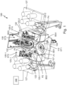
- Fig. 1 shows an oblique perspective view of an embodiment of a processing machine 100 designed as a rotary transfer machine, which is configured as a coating machine for coating workpieces in the form of brake disks BS1 to BS4.
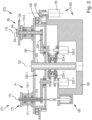
- Fig. 2 shows a split sectional view of the coating machine with components of the drive system.
- the cutting planes to the left and right of a central rotary table axis 152 are offset by 90° from each other, ie the illustration shows two cutting planes rotated by 90° to each other.
- Each of the brake discs has a base body made of gray cast iron, for example, with a central hub section NA, which is used to attach the brake disc to a vehicle axle, and a circular brake section BA, which encloses the hub section.
- the mass distribution of the base body is overall rotationally symmetrical to the axis of rotation RB of the brake disc.
- the brake section has two axially opposite, parallel surfaces. These should each be provided with a coating or functional layer that is rotationally symmetrical with respect to the axis of rotation, the free surface of which should ultimately serve as the friction surface of the brake disc.
- the circular braking surfaces on both sides are to be coated using a special variant of laser cladding, namely a variant of extreme high-speed laser cladding, which is also known under the term "EHLA process".
- the coating machine 100 is configured as a numerically controlled rotary transfer machine with a total of four work stations. All functions are implemented via control commands from a control unit 190, which can be located locally (on or next to the machine) or remotely, e.g. in another room.
- a loading and unloading station 110 which is also referred to here as the first station ST1.
- a brake disk (here BS1) is mounted in a horizontal orientation, i.e. with a vertically aligned rotation axis ("turntable arrangement"), on a workpiece spindle, which will be described later.
- the attachment can be made, for example, by clamping it to a workpiece holding device on the workpiece spindle in such a way that the brake disk is clamped or mounted in a rotationally fixed manner and the rotation axis of the brake disk is coaxial with the spindle rotation axis.
- a rotationally fixed connection to the workpiece spindle can also be achieved by holding it down or holding it from above.
- a brake disk loaded in this way is then transported by rotating the rotary table 90° clockwise to a processing position in a first laser coating station 120-1, which is also referred to as the second station ST2.
- a first laser coating station 120-1 which is also referred to as the second station ST2.
- the top first side of the brake section of the brake disk is coated.
- a further 90° cycle moves the brake disk coated on one side to a turning station 130 (third station ST3), in which the brake disk coated on one side is gripped by means of a manipulator, removed from the workpiece holding device and rotated by 180° about an axis perpendicular to the axis of rotation, so that the previously bottom, still uncoated second side is on top. In this orientation, the brake disk is placed back on the workpiece spindle and clamped tight.
- a further cycle of 90° then brings the brake disc to a second laser coating station 120-2 (fourth station ST4), in which the previously uncoated second side of the brake disc is coated.
- the brake disc which is coated on both sides, is then rotated 90° and transported to the first station ST1, i.e. to the loading and unloading station 110, from where it can be unloaded, for example, by means of a robot or another handling device or manually.
- a brake disc to be newly coated can be clamped onto the workpiece spindle that is then freed up, so that, with the exception of the changeover times, all four workpiece spindles are occupied by brake discs and are each in different phases of processing or coating.
- laser processing unit here refers to an application device that radiates a powdered starting material, usually a metal powder, in the direction of the surface to be coated and at the same time guides a laser beam that is focused in the EHLA process so that the metal powder is melted before reaching the workpiece surface and is then deposited in the melted state onto the workpiece surface to form the functional layer.
- the metal powder is kept in separate storage containers and fed to the laser processing units by powder conveyors 127.
- the laser processing units each have drives for a horizontal or an axial movement. With the horizontal movement, the laser processing unit can be moved in the radial direction to the rotation axis of the workpiece in order to Laser welding tracks are applied in a spiral shape to the surface to be coated.
- the axial movement is used for the feed and for setting the exact distance to the surface.
- the coating unit designed as a laser processing unit can be oriented in relation to the surface to be coated in such a way that the melting laser beam is oriented essentially in the normal direction to the surface.
- the coating unit designed as a laser deposition welding unit has a main axis running parallel to the beam exit direction of the laser beam, which is set at an angle of inclination of more than 5°, e.g. up to approx. 10°, to the spindle rotation axis and/or to the surface normal of the surface to be coated. This makes it easy to avoid disruptions to the coating process caused by laser radiation reflected from the surface to be coated. This enables continuous operation of the coating unit with essentially uniform application properties without significant traces of smoke.
- the turning station 130 (third station ST3) has a gripper 132 that can grip the brake disk at its circumference, as well as a drive for turning the workpiece by rotating the gripper about a horizontal axis of rotation.
- a vertical translatory machine axis is provided for the gripper for lifting and placing.
- an internal machine transport system is used with a rotary table or turntable 150, which is mounted on or in the machine base 160 so that it can rotate about a vertical rotary table axis 152 and can be rotated without limit about the vertical rotary table axis using a rotary table drive 155.
- the plate-shaped rotary table is mounted so that it can rotate on a base plate 162 fixed to the frame using cross roller bearings. As in Fig.
- the rotary table drive 155 is mounted laterally next to the rotary table on the base plate 162 and drives the rotary table via a toothed belt 156 which runs over the toothed circumference of the rotary table and a corresponding drive gear on the output shaft of the rotary table drive.
- the brake discs To carry out the coating process, the brake discs must be rotated around their axis of rotation, at the same time the laser coating is carried out more or less spirally from the inside to the outside or vice versa by moving the laser processing units radially to the axis of rotation of the brake discs.
- the speed is is continuously changed so that the local application speed is essentially constant throughout the entire part of the braking section to be coated.
- the brake discs should be set into a relatively fast rotation for the coating process; typical operating speeds for the coating process can be in the range of several hundred revolutions per minute, for example between 200 rpm and 600 rpm. This is achieved as follows.
- the rotary table 150 or the rotary table plate, which serves as the spindle carrier unit 150, carries four workpiece spindles 170-1 etc., each offset by 90°, at four positions P1 to P4, each offset by 90°.
- Two workpiece spindles 170-1 and 170-2, which are at 90° to each other, at positions P1 and P2 are in Fig. 2 visible in longitudinal section.
- Each of the workpiece spindles is mounted in a bearing sleeve 171 fixedly mounted on the top of the rotary table 150 so that it can rotate without limit about a vertical spindle rotation axis 172 relative to the bearing sleeve or rotary table 150.
- Each freely rotatable workpiece spindle has a clamping head 173 at its upper end, which serves as an adjustable workpiece holding device 173 for fastening the brake disk BS.
- the clamping head is actuated from below by means of a pneumatic actuator 180. A flat contact surface of the brake disk rests on the flat top of the clamping head.
- the actuators 180 for operating the clamping head or the workpiece holding device 173 are not attached to the rotary table 150, but are mounted on a console of the machine frame 160 in the area of the loading station and the turning station.
- the clamping head 173 is operated via a pressure rod 174 that protrudes from the lower end of the workpiece spindle.
- the clamping head is pre-tensioned in the clamping configuration so that in the absence of pressure the clamping head clamps the workpiece. Pressure from below on the pressure rod releases the workpiece.
- a hold-down device can also be provided.
- the circular sector-shaped areas of the workpiece spindles or the brake disks attached to them are mechanically separated from each other on the top of the rotary table 150.
- an arrangement with vertical protective plates 157 is provided on the top of the rotary table. which each delimit a 90° sector around a workpiece spindle from the other sectors.
- Each of the laser processing stations 170-1, 170-2 has its own cover or housing 125-1, 125-2, which largely encloses the associated work area, i.e. the area of interaction between the laser processing unit and the brake disk.
- the laser processing unit protrudes from above through an upper passage opening of this housing into the work area enclosed by the housing.
- the drive system 200 for rotating the workpiece spindles or the brake disks mounted thereon has some special features which are described below, especially with reference to the Fig. 2 be explained in more detail.
- the workpiece spindles 170-1 etc. are carried by the rotary table 150, which serves as the spindle support unit 150.
- the drives for generating the rotary movement of the workpiece spindles i.e. the spindle drives, are not attached to the rotary table, but are fixed in place or fixed to the frame on a component of the machine frame 160 in the area below the base plate 162.
- the rotary table 150 therefore has no moving spindle drives for the tool spindles. This saves a considerable amount of weight.
- first spindle drive 220-1 second spindle drive 220-2
- first spindle drive 220-1 second spindle drive 220-2
- the torque for rotating a workpiece spindle is transmitted from the associated frame-mounted spindle drive to the workpiece spindle using a torque transmission device (general reference numeral 230).
- the drive system 200 has two independent drive trains for the four workpiece spindles, whereby two diametrically opposed workpiece spindles are driven by a common spindle drive.
- the spindle drive is permanently coupled to the two associated workpiece spindles, so that torque can be transmitted not only when a workpiece spindle is in one of the working positions, but also while the rotary table is rotating to switch between work stations. The torque is therefore transmitted independently of the work stations. This makes it possible to drive a workpiece spindle while the rotary table is rotating.
- the spindle drives are installed in a fixed location, which makes it easy to supply energy to the drives.
- Both drive trains run coaxially to each other and coaxially to the rotary table axis.
- nested hollow shafts are integrated into the drive trains, which have drive elements and output elements staggered in height.
- the exemplary embodiment of the coating machine has four work stations ST1 to ST4, namely the loading and unloading station (first station ST1), the two laser processing stations (second station ST2 and fourth station ST4) and the turning station (third station ST3). These stations are fixed in space or in relation to the machine frame 160.
- the rotating plate 150 of the rotary table which serves as a spindle carrier unit, carries four workpiece spindles at four positions P1 to P4, each 90° circumferentially offset from one another.
- the "positions" of the workpiece spindles rotate with the rotary table.
- Each rotary table position P1 to P4 is successively moved to each of the work stations ST1 to ST4 by the rotation of the rotary table.
- positions P1 and P3 as well as positions P2 and P4 are diametrically opposite each other to the rotary table axis.
- the vertical cut in the left part of Fig. 2 passes through the loading and unloading station or the turning station, which are diametrically opposite each other.
- the brake disc BS is mounted on the top of a workpiece spindle (right part of Fig. 2 ), for example, there is a laser processing station.
- the workpiece spindles at position P1 and position P3 (in Fig. 2 not shown) of the rotary table are diametrically opposed to each other in relation to the rotary table axis. They are driven by a common first spindle drive 220-1, which is fixedly mounted on a component of the machine frame 160 with its output shaft aligned vertically.
- the first spindle drive 220-1 is constantly in drive connection with the two associated workpiece spindles via a torque transmission device 230-1 consisting of several components.
- the torque transmission device 230-1 comprises a gear 222 mounted on the output shaft of the first spindle drive, which meshes with a lower gear ring of a first hollow shaft 224-1, which is rotatably mounted coaxially to the rotary table axis 152 and has an upper gear ring at an axial distance above the lower gear ring.
- the first spindle drive 220-1 is permanently in drive connection with each of the two diametrically opposite workpiece spindles at positions P1 and P3.
- a second spindle drive 220-2 which is mounted on the machine and drives a gear wheel which engages a lower gear ring of a second hollow shaft 224-2, which is also rotatably mounted coaxially to the rotary table axis 152.
- the second hollow shaft also has an output-side gear ring axially offset from the drive-side gear ring, which is in Fig. 2 can be seen above the output-side gear ring for the first drive train.
- the transmission of the rotation to the associated workpiece spindles is then again carried out via a transmission element with two gear rings and a toothed belt, which also runs around the workpiece spindles.
- the two drive trains for the respective pairs of workpiece spindles are therefore arranged in the area of the interconnected hollow shafts 224-1, 224-4 coaxially to each other and coaxially to the rotary table axis 152.
- the lower gear rings of the hollow shafts each serve as a drive element, the upper gear rings as an output element of the respective hollow shaft.
- the two hollow shafts sit on an inner bearing sleeve 225, which is attached to the rotary table 150, centered on the rotary table axis 152.
- the bearing sleeve has an inner through-channel, which can be used as a supply channel for cables for connecting any components on the rotary table (optional).
- the coating machine 100 can be operated as follows. In a coating process, a brake disk coated on both sides has just been removed from the loading and unloading station 110 manually, semi-automatically or automatically using a handling system. To do this, the pressure rod 174 of the clamping head was pneumatically actuated from below using the actuator 180 so that it released the brake disk. A new, still uncoated brake disk or its base body is clamped onto the now free clamping head. By releasing the clamping head, it switches to a clamping configuration that is stored without energy and thus grips the workpiece securely even in the event of any malfunctions. When the workpiece is placed on top and when it is clamped, the workpiece spindle 170-1 does not rotate.
- the rotary table is indexed.
- the spindle drive is braked so that the rotary movement of the brake disc coated on one side is slowed down and it reaches the turning station 130 rotating more or less slowly or already at a standstill.
- the brake disc is gripped by a gripper on its outer circumference, released from the workpiece holding device by lowering the workpiece spindle and/or raising the workpiece gripper, turned by 180° and then placed back on the Workpiece spindle is attached.
- the pressure is released by pressing on the pressure rod from below. Once the brake disc is reattached, the pressure is released and the clamping head clamps the workpiece automatically.
- the spindle drive is started up again so that the brake disk coated on one side is accelerated to its working speed on the way to the second laser processing station (station ST3) and arrives there already rotating quickly so that the laser coating operation can begin immediately after the workpiece spindle arrives at the correct working position.
- the first spindle drive brakes the workpiece spindle again before starting and during the journey to the loading and unloading station so that the workpiece can be unloaded there immediately after arrival.
- one embodiment provides for the workpiece to be cleaned after completion of the first coating operation and before the start of the turning operation and/or after the second coating operation and before removal. This allows loose residues of coating material and/or powder residues to be removed, thereby preventing such contamination from being carried over to subsequent operations. Cleaning can be carried out, for example, by suction and/or by blowing off the contamination. Alternatively or additionally, the workpiece can be stimulated with ultrasound for cleaning or to assist with cleaning in order to release loosely bound contamination from the workpiece. Such cleaning operations can potentially significantly improve the final quality of the coated brake disc.
- Such a coating machine can initially take uncoated brake disc base bodies and apply a functional layer on both sides. Only very short cycle times are required for this, particularly because acceleration processes to the working speed can be initiated and, if necessary, completed before the brake disc arrives at the respective laser processing station. This means that there are only minimal waiting times within the laser processing station. This means that even when the powder feed in the laser processing stations is running continuously, very little time and material is wasted between the individual coating operations. This enables highly productive production of brake discs coated on both sides at low overall costs, particularly for operating resources.
- a production system 400 for producing coated brake disks is explained.
- Two coating machines 100A and 100B of the type described and a grinding machine 460 are integrated into the production system, which can also be constructed as a processing machine of the type described here (without moving spindle drives).
- the functional coating for the brake disks should have two layers, namely an adhesive layer applied directly to the metal base body and a wear layer applied to it, which is significantly harder than the gray cast iron material of the base body.
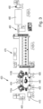
- the production plant 400 comprises Fig. 3 on the left is a pre-test station 410, in which the delivered brake disc base bodies are tested for suitability for coating.
- type recognition also takes place in the pre-test station.
- Certain characteristic features of the delivered base bodies e.g. external diameter, type and size of contact surfaces and/or distance between the rotation axis and friction surface
- the programming of the processing machines can then be selected automatically. This means that the production plant is in principle able to work with small series down to batch size 1.
- the standardized usable base bodies are then conveyed to a coating system 420 using a linear conveyor line.
- a coating system 420 This comprises, in a substantially circular arrangement, an input measuring station 422, a first coating machine 100A for producing the adhesive layer on both sides, a downstream control unit 424 for controlling the coating properties of the adhesive layer, a downstream second coating unit 100B for producing the wear layer on both sides of the brake disc and a downstream control station 426 for controlling the quality of the wear layer.
- the transfer to these individual units and the finished or tested brake discs from these units is achieved via a central robot unit 440, the working area of which extends to the loading and unloading stations of the two coating machines and the corresponding stations of the control stations.
- the coated brake discs After completion of the two individual layers of the functional coating, the coated brake discs have heated up; typical temperatures can be in the range of up to 200 °C or more. Furthermore, the free surface of the wear layer is usually still relatively rough or grooved because it is formed by the free backs of laser deposition welding beads. In addition, the layer thicknesses on the two sides may be different and/or the total thickness may still be too large. To eliminate these defects, a grinding station 460 is provided in the production plant.
- a cooling section 470 is connected between the coating stations and the grinding station, in which the brake disks, which are still warm after laser coating, can cool down to approximately room temperature.
- the cooling section also serves as a buffer to compensate for possible differences in working speeds between the coating system and the grinding machine.
- the grinding machine can have a movable spindle carrier unit with two or more workpiece spindles, the associated spindle drives of which do not move with the spindle carrier unit, but are mounted on the frame.
- a turning station may or may not be provided. In the example, both surfaces are ground simultaneously using a variant of double-sided surface grinding, so that a turning station can be omitted.
- multi-stage grinding processes can be implemented, e.g. a two-stage grinding process with pre-grinding and fine grinding. These operations can be integrated in a single processing machine if necessary. It is also possible to provide two separate processing machines for pre-grinding and subsequent fine grinding.
- the brake discs are conveyed to a washing station 480, which they leave in the direction of a final measuring station 490.
- the entire production system is controlled via a central control unit 405. In this way, cycle times of the individual processing stations can be coordinated so that a continuous production process with high unit output can be realized.
- Fig. 3 is just one possible variant for the design of a production plant.
- the components could be arranged differently depending on the space available, e.g. in a U-arrangement, an I-arrangement or an O-arrangement.
- Processing machines and other stations can be arranged along the sides of a main conveyor line and served by cross conveyors.
- Fig. 4 , 5 and 6 show various alternatives by way of example.
- the associated transport system in each case has a spindle carrier unit in the form of a rotary table 150 with a vertical rotary table axis 152.
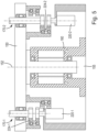
- FIG. 4 the cutting planes to the left and right of the central rotary table axis 152 are offset by 90° from each other, ie the illustration shows two cutting planes rotated by 90° to each other.
- a hollow carrier 156 is mounted centrally on the machine frame 160 so that it can rotate about the vertical rotary table axis 152.
- the first spindle drive 220-1 is arranged within the hollow carrier 155, the output of which is coaxial with the rotary table axis and is coupled to a gear which is at the level of the rotary table plate.
- a workpiece spindle 170-1 On the left, a workpiece spindle 170-1 is shown, which carries a gear ring that is coupled to the central gear wheel via a larger gear ring in between, transmitting torque.
- the same arrangement is found diametrically opposite one another on the real rotary table, so that two diametrically opposite workpiece spindles are driven together by the first spindle drive 220-1 and are constantly in drive connection with it.
- the workpiece spindles which are offset by 90° around the circumference (right part of the figure), are driven by the second spindle drive 220-2. Its output gear meshes with the lower gear of a hollow shaft 224-2, which is arranged concentrically to the rotary table axis 152 and has an upper gear ring at an axial distance from the lower gear ring, which meshes with a gear ring that is attached to the lower end of the workpiece spindle unit 170-2. If the spindle motor is rotated, the hollow shaft rotates around the rotary table axis and thereby drives the rotation of the coupled workpiece spindles.
- a hollow shaft 224-2 coaxial to the rotary table is provided only on one drive train (from the second spindle drive).
- a second alternative design option for the drive system is shown.
- the rotary table drive 155 is arranged centrally to the rotary table rotation axis; it can be a central torque motor, for example.
- the rotary table plate is mounted on a carrier shaft that is rotatably mounted on the machine frame 160.
- the left-hand part of the figure shows the first spindle drive 220-1, which is coupled to the workpiece spindles at positions P1 and P3.
- At the upper end of the output shaft there is a drive gear that meshes with a lower gear ring of a first hollow shaft 224-1 that is rotatably mounted with inwardly directed teeth on the underside of the rotary table 150 about the rotary table's rotation axis.
- the hollow shaft has an axially offset upper gear ring, the inwardly directed teeth of which mesh with a gear at the lower end of the workpiece spindle 170-1 to be driven.
- the right-hand part of the figure shows the drive train that originates from the second spindle motor 220-2 and drives the spindles at positions P2 and P4.
- the torque transmission device comprises a second hollow shaft 224-2, which is rotatably mounted on a bearing element attached to the underside of the rotary table coaxially to the rotary table axis 152.
- the outward-facing upper toothing of the second hollow shaft meshes with a gear at the lower end of the associated workpiece spindle 170-2.
- This solution thus uses two hollow shafts 224-1, 224-2, each rotatable coaxially to the rotary table axis 152, each having toothing at different axial levels.
- FIG. 6 A third alternative is shown schematically, with the partial figures to the left and right of the rotary table axis representing cutting planes offset by 90°.
- the rotary table output is mounted within the central area of the machine frame 160, for example in the area of the rotary table axis.
- the first spindle motor 220-1 shown on the left for the positions P1 and P3 of the tool spindles drives a first hollow shaft 224-1 with its output gear, which is mounted on the machine frame with outward-facing teeth so that it can rotate coaxially around the rotary table axis.
- the upper gear ring of the hollow shaft meshes with the drive gear of the workpiece spindle 170-2 at position P1.
- the torque transmission device comprises a second hollow shaft 224-2, which is rotatably mounted relative to the first hollow shaft 224-1 and relative to the machine frame 160 coaxially to the rotary table axis.
- This hollow shaft absorbs the rotary movement of the output gear of the second spindle drive and transmits it via its upper gear ring to the input-side drive gear of the workpiece spindle.
- a specialist can use these variants or variations thereof depending on the ambient conditions and the needs of the drive to drive workpiece spindles mounted on a rotating spindle carrier unit (here a rotary table) with spindle drives mounted on the frame. While the torque transmission in the examples is mainly via gears, other drive elements, such as belts or the like, can also be used at some points in the drive train.
Landscapes
- Engineering & Computer Science (AREA)
- General Engineering & Computer Science (AREA)
- Mechanical Engineering (AREA)
- Turning (AREA)
- Laser Beam Processing (AREA)
- Braking Arrangements (AREA)
- Grinding Of Cylindrical And Plane Surfaces (AREA)
Claims (15)
- Machine de traitement (100) pour l'utilisation lors de la fabrication d'un disque de frein (BS) revêtu, qui présente un corps de base qui présente une distribution de masse à symétrie de révolution par rapport à un axe de rotation (RA) du disque de frein et comprend une partie moyeu (NA) centrale ainsi qu'une partie de freinage (BA) de forme annulaire circulaire entourant la partie moyeu, la partie de freinage présentant deux surfaces axialement opposées qui supportent respectivement une couche fonctionnelle à symétrie de révolution par rapport à l'axe de rotation, dont la surface libre est réalisée comme surface de friction du disque de frein, la machine de traitement comprenant :une base de machine (160) ;un système de transport comportant une unité de support de broche (150) mobile par rapport à la base de machine, laquelle unité supporte au moins une broche porte-pièce (170), laquelle est montée rotative autour d'un axe de rotation de broche (172) par rapport à l'unité de support de broche (150) et présente un dispositif de retenue de pièce (173) qui est réalisé de telle sorte qu'un corps de base logé sur dispositif de retenue de pièce (173) peut être entraîné en rotation lors de la rotation de la broche porte-pièce (170) sensiblement autour de l'axe de rotation (RA) coaxial à l'axe de rotation de broche (172) ;plusieurs postes de travail (ST1 à ST4) disposés le long d'une voie de transport et pouvant être atteints par la broche porte-pièce (170), lesquels comprennent un poste de chargement (110, ST1) et au moins un poste de traitement (120-1, 120-2) comportant au moins une unité de traitement (125) pour le traitement d'au moins un côté de la partie de freinage ;un système d'entraînement (200) comportant au moins un entraînement de broche (220) pour la génération de mouvements rotatifs de la broche porte-pièce (170) autour de l'axe de rotation de boche en réaction à des signaux de commande d'une unité de commande (190),caractérisée en ce quele système d'entraînement (200) et l'unité de commande (190) sont configurés de telle sorte qu'une broche porte-pièce (170), après la fixation d'un disque de frein au dispositif de retenue de pièce dans le poste de chargement (110), avant que le poste de traitement ne soit atteint, peut être mise en rotation à une vitesse de rotation croissante à l'aide d'un entraînement de broche associé, de telle sorte que la pièce logée sur la broche porte-pièce peut être déplacée de manière rotative dans la position de traitement à une vitesse de rotation d'entrée.
- Machine de traitement selon la revendication 1, caractérisée en ce que le système d'entraînement (200) et l'unité de commande (190) sont configurés de telle sorte qu'une accélération d'un mouvement rotatif de la broche porte-pièce commence immédiatement après la fixation de la pièce au dispositif de retenue de pièce, avant que l'unité de support de broche ne soit mise en mouvement, afin de transporter la broche porte-pièce jusqu'au poste de traitement.
- Machine de traitement selon la revendication 1 ou 2, caractérisée en ce que le système d'entraînement (200) et l'unité de commande (190) sont configurés de telle sorte que la broche porte-pièce est accélérée jusqu'à une vitesse de rotation de travail, prévue pour une opération de traitement dans le poste de traitement, de plus de 100 tr/min, en particulier jusqu'à une vitesse de rotation de travail dans la plage de 150 tr/min à 600 tr/min, la vitesse de rotation d'entrée correspondant sensiblement à la vitesse de rotation de travail souhaitée pour l'opération de traitement, de sorte que l'opération de traitement puisse commencer sans retard dès que la pièce se trouve dans la position de traitement, ou la vitesse de rotation d'entrée étant inférieure à la vitesse de rotation de travail, de sorte qu'une autre phase d'accélération courte soit encore nécessaire.
- Machine de traitement selon la revendication 1, 2 ou 3, caractérisée en ce que le système d'entraînement (200) présente au moins un entraînement de broche (220) monté de manière solidaire du bâti et un dispositif de transmission de couple (230) pour la transmission de couples de l'entraînement de broche à au moins une broche porte-pièce (170) associée, l'unité de support de broche (150) supportant de préférence plusieurs broches porte-pièce, en particulier trois ou quatre broches porte-pièce (170-1 à 170-4), et un entraînement de broche (220-1, 220-2) associé monté de manière solidaire du bâti étant prévu pour chacune des broches porte-pièce.
- Machine de traitement selon l'une des revendications précédentes, caractérisée en ce que le système d'entraînement est configuré de telle sorte que chaque broche porte-pièce (170) est en permanence en liaison d'entraînement avec un entraînement de broche (220) associé, en particulier également pendant un mouvement de l'unité de support de broche (150).
- Machine de traitement selon l'une des revendications précédentes, caractérisée en ce que le système de transport présente, comme unité de support de broche (150), une table ronde (150) qui peut être entraînée en rotation autour d'un axe de table ronde (152) de préférence vertical à l'aide d'un entraînement de table ronde (155) et en ce que plusieurs broches porte-pièce (170) sont disposées sur la table ronde de telle sorte qu'elles peuvent être transportées sur une voie de transport circulaire ou en forme d'arc de cercle entre des postes de travail (ST1 à ST4) de la machine de traitement, des broches porte-pièce (170) étant de préférence distribuées sur la table ronde (150) de telle sorte qu'il y ait des paires de broches porte-pièce, une paire d'un entraînement de broche (220-1 ; 220-2) commun étant respectivement prévue pour deux broches porte-pièce (170-1, 170-3 ; 170-2, 170-4), les broches porte-pièce d'une paire étant de préférence diamétralement opposées l'une à l'autre par rapport à l'axe de table ronde (152) et/ou un arbre creux (224) rotatif coaxialement avec l'axe de table ronde (152) étant intégré dans au moins un dispositif de transmission de couple entre un entraînement de broche (220) et plusieurs broches porte-pièce (170) accouplées par entraînement à celui-ci, lequel arbre creux présente un élément d'entraînement et un élément de sortie de manière étagée axialement, deux chaînes cinématiques comportant des arbres creux (224-1, 224-2) emboîtés l'un dans l'autre et dotés d'éléments d'entraînement et d'éléments de sortie étagés en hauteur étant de préférence intégrées.
- Machine de traitement selon l'une des revendications précédentes, caractérisée en ce que la machine de traitement est configurée comme machine de revêtement (100), au moins un poste de traitement étant configuré comme un poste de revêtement comportant au moins une unité de revêtement, la machine de revêtement (100) présentant de préférence au moins deux, en particulier exactement deux postes de travail disposés séparément les uns des autres, lesquels sont conçus comme des postes de revêtement.
- Machine de traitement selon la revendication 7, caractérisée en ce que la machine de revêtement (100) est conçue pour un revêtement bilatéral d'un disque de frein, de préférence de telle sorte qu'une première opération de revêtement pour le revêtement d'un premier côté et une deuxième opération de revêtement pour le revêtement d'un deuxième côté, opposé axialement au premier côté, de la partie de freinage peuvent être effectuées successivement dans le temps et/ou caractérisée en ce que la machine de revêtement (100) présente plusieurs postes de travail (ST1 à ST4) disposés le long de la voie de transport du système de transport, qui présentent, dans cet ordre, un poste de chargement (110), un premier poste de revêtement (120-1) comportant au moins une unité de revêtement pour le revêtement d'un premier côté d'un disque de frein, un poste de retournement (130) pour le retournement d'un disque de frein logé sur une broche porte-pièce et au moins un deuxième poste de revêtement (120-2) pour le revêtement d'un deuxième côté du disque de frein ainsi qu'un poste de déchargement, le poste de chargement fonctionnant de préférence comme poste de déchargement également.
- Machine de traitement selon la revendication 7 ou 8, caractérisée en ce qu'une unité de revêtement est réalisée comme un dispositif de rechargement laser qui, lors du fonctionnement, projette une poudre métallique en direction de la surface à revêtir et guide simultanément un faisceau laser qui est de préférence focalisé de telle sorte que la poudre métallique, avant d'atteindre la surface de la pièce, est fondue et est déposée dans l'état fondu sur la surface de la pièce, afin de former la couche fonctionnelle et/ou en ce qu'une unité de revêtement est déplaçable de manière commandée en entraînement verticalement ainsi qu'horizontalement et/ou une surface sur le côté de la pièce orienté vers le haut peut être revêtue dans chaque opération de revêtement.
- Procédé pour l'utilisation d'un disque de frein (BS) revêtu, qui présente un corps de base qui présente une distribution de masse à symétrie de révolution par rapport à un axe de rotation (RA) du disque de frein et comprend une partie moyeu (NA) centrale ainsi qu'une partie de freinage (BA) de forme annulaire circulaire entourant la partie moyeu, la partie de freinage (BA) présentant deux surfaces axialement opposées qui supportent respectivement une couche fonctionnelle à symétrie de révolution par rapport à l'axe de rotation, dont la surface libre est réalisée comme surface de friction du disque de frein,
le procédé comprenant les étapes suivantes :fourniture d'un système de transport comportant une unité de support de broche (150) mobile, qui supporte au moins une broche porte-pièce (170), laquelle est montée rotative autour d'un axe de rotation de broche (172) par rapport à l'unité de support de broche et présente un dispositif de retenue de pièce (173) qui est réalisé de telle sorte qu'un corps de base, logé sur le dispositif de retenue de pièce, d'un disque de frein est entraîné en rotation lors de la rotation de la broche porte-pièce sensiblement autour de l'axe de rotation (RA) du corps de base ;fixation du corps de base au dispositif de retenue de pièce (170) ;mouvement de l'unité de support de broche (150) du système de transport pour le transport du corps de base logé sur la broche porte-pièce dans une position de traitement d'un poste de traitement (120) ;traitement de la partie de freinage (BA) sur au moins l'un des côtés, la pièce étant entraînée en rotation par rotation de la broche porte-pièce (170) à une vitesse de rotation de travail autour de l'axe de rotation de broche,caractérisé en ce quela broche porte-pièce (170), après la fixation de la pièce au dispositif de retenue de pièce (173), avant que la position de traitement ne soit atteinte, est mise en rotation à une vitesse de rotation croissante et la pièce logée sur la broche porte-pièce est déplacée dans la position de revêtement de manière déjà rotative à une vitesse de rotation d'entrée. - Procédé selon la revendication 10, caractérisé en ce que l'accélération du mouvement rotatif commence immédiatement après la fixation de la pièce au dispositif de retenue de pièce, avant que l'unité de support de broche ne soit mise en mouvement, afin de transporter la broche porte-pièce jusqu'au poste de traitement.
- Procédé selon la revendication 10 ou 11, caractérisé en ce que la broche porte-pièce est accélérée jusqu'à une vitesse de rotation de travail, prévue pour une opération de traitement dans le poste de traitement, de plus de 100 tr/min, en particulier jusqu'à une vitesse de rotation de travail dans la plage de 150 tr/min à 600 tr/min, la vitesse de rotation d'entrée correspondant sensiblement à la vitesse de rotation de travail souhaitée pour l'opération de traitement, de sorte que l'opération de traitement puisse commencer sans retard dès que la pièce se trouve dans la position de traitement, ou la vitesse de rotation d'entrée étant inférieure à la vitesse de rotation de travail, de sorte qu'une autre phase d'accélération courte soit encore nécessaire.
- Procédé selon l'une des revendications 10 à 12, caractérisé en ce que le traitement comprend la génération d'un revêtement fonctionnel à symétrie de révolution par rapport à l'axe de rotation sur au moins un côté de la partie de freinage dans une opération de revêtement, le corps de base étant entraîné en rotation par rotation de la broche porte-pièce à une vitesse de rotation de travail autour de l'axe de rotation de broche et une matière de revêtement étant appliquée par une unité de revêtement sur la surface à revêtir, la pièce présentant de préférence un premier côté et un deuxième côté de manière opposée dans une direction axiale et, dans une première opération de revêtement, une première couche fonctionnelle à symétrie de révolution étant appliquée sur une région de surface du premier côté et, dans une deuxième opération de revêtement, une deuxième couche fonctionnelle à symétrie de révolution étant appliquée sur une région de surface du deuxième côté, la première et la deuxième opération de revêtement étant effectuées de préférence successivement dans le temps et/ou la pièce étant fixée au dispositif de retenue de pièce dans une première orientation pour la première opération de revêtement, détachée du logement de pièce après la première opération de revêtement, retournée de la première orientation à une deuxième orientation dans une opération de retournement et fixée au dispositif de retenue de pièce dans la deuxième orientation.
- Installation de production pour la fabrication de disques de frein (BS) revêtus, qui présentent un corps de base qui présente une distribution de masse à symétrie de révolution par rapport à un axe de rotation (RA) du disque de frein et comprend une partie moyeu (NA) centrale ainsi qu'une partie de freinage (BA) de forme annulaire circulaire entourant la partie moyeu, la partie de freinage présentant deux surfaces axialement opposées qui supportent respectivement une couche fonctionnelle à symétrie de révolution par rapport à l'axe de rotation, dont la surface libre est réalisée comme surface de friction du disque de frein,
caractérisée en ce que
l'installation de production présente au moins une machine de traitement (100A, 100B) selon l'une des revendications 1 à 9. - Installation de production selon la revendication 14, caractérisée par au moins l'une des caractéristiques suivantes :(i) l'installation de production présente une ou plusieurs des machines de traitement qui sont configurées comme des machines de revêtement (100A, 100B) pour le revêtement bilatéral d'un disque de frein, une machine de revêtement présentant de préférence au moins une unité de rechargement laser qui est configurée pour projeter une poudre métallique en direction de la surface à revêtir et guider simultanément un faisceau laser qui est focalisé dans une zone de focalisation de telle sorte que la poudre métallique est fondue dans la zone de focalisation et déposée sur la surface de la pièce, afin de former la couche fonctionnelle ;(ii) l'installation de production présente au moins une machine à rectifier (460) placée en aval de la dernière machine de revêtement, laquelle machine à rectifier est conçue de préférence comme machine de traitement selon l'une des revendications 1 à 9, une voie de refroidissement (470) étant disposée de préférence entre la machine de revêtement et la machine à rectifier pour le refroidissement de disques de frein revêtus.
Priority Applications (2)
| Application Number | Priority Date | Filing Date | Title |
|---|---|---|---|
| HRP20250500TT HRP20250500T1 (hr) | 2022-08-25 | 2023-07-13 | Stroj za preradu i postupak kao i proizvodno postrojenje za proizvodnju obloženih kočnih diskova |
| RS20250462A RS66804B1 (sr) | 2022-08-25 | 2023-07-13 | Mašina za obradu i postupak, kao i proizvodno postrojenje za proizvodnju obloženih kočionih diskova |
Applications Claiming Priority (1)
| Application Number | Priority Date | Filing Date | Title |
|---|---|---|---|
| DE102022208788.7A DE102022208788A1 (de) | 2022-08-25 | 2022-08-25 | Bearbeitungsmaschine und Verfahren sowie Fertigungsanlage zur Herstellung von beschichteten Bremsscheiben |
Publications (3)
| Publication Number | Publication Date |
|---|---|
| EP4332407A1 EP4332407A1 (fr) | 2024-03-06 |
| EP4332407C0 EP4332407C0 (fr) | 2025-03-05 |
| EP4332407B1 true EP4332407B1 (fr) | 2025-03-05 |
Family
ID=87280989
Family Applications (1)
| Application Number | Title | Priority Date | Filing Date |
|---|---|---|---|
| EP23185287.2A Active EP4332407B1 (fr) | 2022-08-25 | 2023-07-13 | Machine d'usinage et procédé ainsi qu'installation de fabrication pour la fabrication de disques de frein revêtus |
Country Status (7)
| Country | Link |
|---|---|
| EP (1) | EP4332407B1 (fr) |
| DE (1) | DE102022208788A1 (fr) |
| ES (1) | ES3018432T3 (fr) |
| HR (1) | HRP20250500T1 (fr) |
| HU (1) | HUE071500T2 (fr) |
| PL (1) | PL4332407T3 (fr) |
| RS (1) | RS66804B1 (fr) |
Families Citing this family (1)
| Publication number | Priority date | Publication date | Assignee | Title |
|---|---|---|---|---|
| CN119347608B (zh) * | 2024-12-18 | 2025-08-29 | 武义史夫克工具股份有限公司 | 一种电磨机磨头抛光机的定位转台总成 |
Citations (5)
| Publication number | Priority date | Publication date | Assignee | Title |
|---|---|---|---|---|
| DE102011100456A1 (de) | 2011-05-04 | 2012-11-08 | Fraunhofer-Gesellschaft zur Förderung der angewandten Forschung e.V. | Extremes Hochgeschwindigkeitslaserauftragsschweißverfahren |
| US20200255231A1 (en) | 2017-07-04 | 2020-08-13 | Mikron Sa Agno | Rotary transfer indexing machine |
| EP3789511A1 (fr) | 2019-09-09 | 2021-03-10 | Sturm Maschinen- & Anlagenbau GmbH | Dispositif de revêtement et procédé de revêtement métallique de pièces |
| WO2021122951A1 (fr) | 2019-12-17 | 2021-06-24 | Chiron Group Se | Dispositif de revêtement de disques de frein, et installation de fabrication pour la réalisation de disques de frein, comprenant un tel dispositif |
| DE102020007581A1 (de) | 2020-12-11 | 2022-06-15 | EMAG GmbH & Co. KG | Vorrichtung und Verfahren zum Beschichten von Bremsscheiben |
Family Cites Families (3)
| Publication number | Priority date | Publication date | Assignee | Title |
|---|---|---|---|---|
| DE2848668A1 (de) * | 1978-11-09 | 1980-05-14 | Guehring Gottlieb Fa | Bearbeitungsautomat |
| JP6335994B2 (ja) * | 2016-09-27 | 2018-05-30 | 旭精機工業株式会社 | 研削装置 |
| JP6774343B2 (ja) * | 2017-01-23 | 2020-10-21 | 株式会社スギノマシン | 工作機械 |
-
2022
- 2022-08-25 DE DE102022208788.7A patent/DE102022208788A1/de active Pending
-
2023
- 2023-07-13 HU HUE23185287A patent/HUE071500T2/hu unknown
- 2023-07-13 ES ES23185287T patent/ES3018432T3/es active Active
- 2023-07-13 PL PL23185287.2T patent/PL4332407T3/pl unknown
- 2023-07-13 EP EP23185287.2A patent/EP4332407B1/fr active Active
- 2023-07-13 RS RS20250462A patent/RS66804B1/sr unknown
- 2023-07-13 HR HRP20250500TT patent/HRP20250500T1/hr unknown
Patent Citations (5)
| Publication number | Priority date | Publication date | Assignee | Title |
|---|---|---|---|---|
| DE102011100456A1 (de) | 2011-05-04 | 2012-11-08 | Fraunhofer-Gesellschaft zur Förderung der angewandten Forschung e.V. | Extremes Hochgeschwindigkeitslaserauftragsschweißverfahren |
| US20200255231A1 (en) | 2017-07-04 | 2020-08-13 | Mikron Sa Agno | Rotary transfer indexing machine |
| EP3789511A1 (fr) | 2019-09-09 | 2021-03-10 | Sturm Maschinen- & Anlagenbau GmbH | Dispositif de revêtement et procédé de revêtement métallique de pièces |
| WO2021122951A1 (fr) | 2019-12-17 | 2021-06-24 | Chiron Group Se | Dispositif de revêtement de disques de frein, et installation de fabrication pour la réalisation de disques de frein, comprenant un tel dispositif |
| DE102020007581A1 (de) | 2020-12-11 | 2022-06-15 | EMAG GmbH & Co. KG | Vorrichtung und Verfahren zum Beschichten von Bremsscheiben |
Non-Patent Citations (9)
| Title |
|---|
| D6.1 - ANGEBOT FA. STURM VOM 4. MAI 2016 |
| D6.2 - AUFTRAGSBESTÄTIGUNG FA. STURM VOM 13. JUNI 2016 |
| D6.3 - BESTELLUNG FA. BUDERUS VOM 16. JUNI 2016 |
| D6.4 - BESTELLBESTÄTIGUNG FA. STURM VOM 6. JULI 2016 |
| D6.5 - LIEFERSCHEIN FA. STURM VOM 23. NOVEMBER 2016 |
| D6.6 - EG-KONFORMITÄTSERKLÄRUNG VOM 27. OKTOBER 2016 |
| D6.7 - ABNAHMEBESTÄTIGUNG FA. BUDERUS VOM 30. JUNI 2017 |
| D6.8 - BETRIEBSANLEITUNG |
| D6.9 - Video zu Aufbau und Betrieb der Anlage |
Also Published As
| Publication number | Publication date |
|---|---|
| RS66804B1 (sr) | 2025-06-30 |
| EP4332407C0 (fr) | 2025-03-05 |
| EP4332407A1 (fr) | 2024-03-06 |
| ES3018432T3 (es) | 2025-05-16 |
| HUE071500T2 (hu) | 2025-09-28 |
| HRP20250500T1 (hr) | 2025-06-20 |
| DE102022208788A1 (de) | 2024-03-07 |
| PL4332407T3 (pl) | 2025-09-08 |
Similar Documents
| Publication | Publication Date | Title |
|---|---|---|
| EP4076824B1 (fr) | Dispositif de revêtement de disques de frein, et installation de fabrication pour la réalisation de disques de frein, comprenant un tel dispositif | |
| EP2138388B1 (fr) | Procédé de fabrication et dispositif de fabrication pour des pièces de carosserie | |
| DE102006019325C5 (de) | Werkzeugmaschine zur Verzahnungsbearbeitung von Werkstücken | |
| EP2137053B1 (fr) | Procédé et dispositif de transport d'outils mobiles | |
| EP2015981B1 (fr) | Dispositif conçu pour usiner des composants d'une carrosserie d'automobile | |
| EP3641972B1 (fr) | Systeme de déplacement et machine à tailler les engrenages | |
| EP3685925B1 (fr) | Procédé et dispositif de peinture par pulvérisation d'une pièce à usiner | |
| DE2904088C2 (de) | Be- und/oder Entladeeinrichtung für Werkzeugmaschinen, insbesondere Drehautomaten | |
| EP4332407B1 (fr) | Machine d'usinage et procédé ainsi qu'installation de fabrication pour la fabrication de disques de frein revêtus | |
| DE102006020924A1 (de) | Vorrichtung zum Bearbeiten von Bauteilen, insbesondere einer Kraftfahrzeugkarosserie | |
| DE102005017523B4 (de) | Verfahren zum Bearbeiten von Werkstücken mittels einer Werkzeugmaschine | |
| EP2675599A1 (fr) | Module de manutention de roues de véhicules automobiles | |
| DE102022116556A1 (de) | Beschichtungsstation für ein zu beschichtendes Werkstück | |
| EP0828572B1 (fr) | Procede de fabrication de pieces annulaires en metal de section profilee et laminoir associe | |
| DE8905157U1 (de) | Mobile Rohrbearbeitungsvorrichtung | |
| EP4433244A1 (fr) | Procédé de transfert automatique de pièces à une machine à tailler les engrenages | |
| DE19818788A1 (de) | Vorrichtung zum Nachbearbeiten von Werkstücken, insbesondere zum Entgraten von Zahnrädern | |
| EP2272624A1 (fr) | Machine rotative dotée de deux broches de pièces usinées | |
| DE2826554C2 (de) | Werkzeugmaschine zum Schleifen der Oberflächen von Werkstücken mit von Magnetfeldern gehaltenem ferromagnetischem Schleifpulver | |
| DE4408517C2 (de) | Verfahren sowie Vorrichtung zur Bearbeitung optisch lesbarer Datenträger | |
| WO2025252276A1 (fr) | Installation de fabrication pour fabriquer des composants de véhicule à moteur, et procédé | |
| DE102022130764A1 (de) | Verfahren zum Beschichten einer Oberfläche | |
| DE19640286A1 (de) | Verfahren und Einrichtung zur Bearbeitung von Werkstücken sowie Werkstückaufnahmestation für eine derartige Einrichtung | |
| DE4336315A1 (de) | Fertigungsstraße zur Herstellung von Ringen | |
| DE202004015632U1 (de) | Werkstückträger |
Legal Events
| Date | Code | Title | Description |
|---|---|---|---|
| REG | Reference to a national code |
Ref country code: HR Ref legal event code: TUEP Ref document number: P20250500T Country of ref document: HR |
|
| PUAI | Public reference made under article 153(3) epc to a published international application that has entered the european phase |
Free format text: ORIGINAL CODE: 0009012 |
|
| STAA | Information on the status of an ep patent application or granted ep patent |
Free format text: STATUS: THE APPLICATION HAS BEEN PUBLISHED |
|
| AK | Designated contracting states |
Kind code of ref document: A1 Designated state(s): AL AT BE BG CH CY CZ DE DK EE ES FI FR GB GR HR HU IE IS IT LI LT LU LV MC ME MK MT NL NO PL PT RO RS SE SI SK SM TR |
|
| STAA | Information on the status of an ep patent application or granted ep patent |
Free format text: STATUS: REQUEST FOR EXAMINATION WAS MADE |
|
| 17P | Request for examination filed |
Effective date: 20240409 |
|
| RBV | Designated contracting states (corrected) |
Designated state(s): AL AT BE BG CH CY CZ DE DK EE ES FI FR GB GR HR HU IE IS IT LI LT LU LV MC ME MK MT NL NO PL PT RO RS SE SI SK SM TR |
|
| GRAP | Despatch of communication of intention to grant a patent |
Free format text: ORIGINAL CODE: EPIDOSNIGR1 |
|
| STAA | Information on the status of an ep patent application or granted ep patent |
Free format text: STATUS: GRANT OF PATENT IS INTENDED |
|
| INTG | Intention to grant announced |
Effective date: 20241004 |
|
| GRAS | Grant fee paid |
Free format text: ORIGINAL CODE: EPIDOSNIGR3 |
|
| GRAA | (expected) grant |
Free format text: ORIGINAL CODE: 0009210 |
|
| STAA | Information on the status of an ep patent application or granted ep patent |
Free format text: STATUS: THE PATENT HAS BEEN GRANTED |
|
| AK | Designated contracting states |
Kind code of ref document: B1 Designated state(s): AL AT BE BG CH CY CZ DE DK EE ES FI FR GB GR HR HU IE IS IT LI LT LU LV MC ME MK MT NL NO PL PT RO RS SE SI SK SM TR |
|
| REG | Reference to a national code |
Ref country code: GB Ref legal event code: FG4D Free format text: NOT ENGLISH |
|
| REG | Reference to a national code |
Ref country code: CH Ref legal event code: EP |
|
| REG | Reference to a national code |
Ref country code: IE Ref legal event code: FG4D Free format text: LANGUAGE OF EP DOCUMENT: GERMAN |
|
| REG | Reference to a national code |
Ref country code: DE Ref legal event code: R096 Ref document number: 502023000648 Country of ref document: DE |
|
| U01 | Request for unitary effect filed |
Effective date: 20250320 |
|
| RAP4 | Party data changed (patent owner data changed or rights of a patent transferred) |
Owner name: NAGEL TECHNOLOGIES GMBH |
|
| REG | Reference to a national code |
Ref country code: ES Ref legal event code: FG2A Ref document number: 3018432 Country of ref document: ES Kind code of ref document: T3 Effective date: 20250516 |
|
| U07 | Unitary effect registered |
Designated state(s): AT BE BG DE DK EE FI FR IT LT LU LV MT NL PT RO SE SI Effective date: 20250424 |
|
| REG | Reference to a national code |
Ref country code: HR Ref legal event code: T1PR Ref document number: P20250500 Country of ref document: HR |
|
| PG25 | Lapsed in a contracting state [announced via postgrant information from national office to epo] |
Ref country code: NO Free format text: LAPSE BECAUSE OF FAILURE TO SUBMIT A TRANSLATION OF THE DESCRIPTION OR TO PAY THE FEE WITHIN THE PRESCRIBED TIME-LIMIT Effective date: 20250605 |
|
| PGFP | Annual fee paid to national office [announced via postgrant information from national office to epo] |
Ref country code: RS Payment date: 20250616 Year of fee payment: 3 |
|
| PGFP | Annual fee paid to national office [announced via postgrant information from national office to epo] |
Ref country code: HR Payment date: 20250617 Year of fee payment: 3 |
|
| REG | Reference to a national code |
Ref country code: HR Ref legal event code: ODRP Ref document number: P20250500 Country of ref document: HR Payment date: 20250617 Year of fee payment: 3 |
|
| PG25 | Lapsed in a contracting state [announced via postgrant information from national office to epo] |
Ref country code: GR Free format text: LAPSE BECAUSE OF FAILURE TO SUBMIT A TRANSLATION OF THE DESCRIPTION OR TO PAY THE FEE WITHIN THE PRESCRIBED TIME-LIMIT Effective date: 20250606 |
|
| PGFP | Annual fee paid to national office [announced via postgrant information from national office to epo] |
Ref country code: TR Payment date: 20250619 Year of fee payment: 3 Ref country code: SK Payment date: 20250623 Year of fee payment: 3 |
|
| PGFP | Annual fee paid to national office [announced via postgrant information from national office to epo] |
Ref country code: CZ Payment date: 20250617 Year of fee payment: 3 |
|
| REG | Reference to a national code |
Ref country code: SK Ref legal event code: T3 Ref document number: E 46480 Country of ref document: SK |
|
| PGFP | Annual fee paid to national office [announced via postgrant information from national office to epo] |
Ref country code: HU Payment date: 20250702 Year of fee payment: 3 |
|
| U20 | Renewal fee for the european patent with unitary effect paid |
Year of fee payment: 3 Effective date: 20250715 |
|
| REG | Reference to a national code |
Ref country code: HU Ref legal event code: AG4A Ref document number: E071500 Country of ref document: HU |
|
| PG25 | Lapsed in a contracting state [announced via postgrant information from national office to epo] |
Ref country code: SM Free format text: LAPSE BECAUSE OF FAILURE TO SUBMIT A TRANSLATION OF THE DESCRIPTION OR TO PAY THE FEE WITHIN THE PRESCRIBED TIME-LIMIT Effective date: 20250305 |
|
| PG25 | Lapsed in a contracting state [announced via postgrant information from national office to epo] |
Ref country code: IS Free format text: LAPSE BECAUSE OF FAILURE TO SUBMIT A TRANSLATION OF THE DESCRIPTION OR TO PAY THE FEE WITHIN THE PRESCRIBED TIME-LIMIT Effective date: 20250705 |
|
| PLBI | Opposition filed |
Free format text: ORIGINAL CODE: 0009260 |
|
| PLAX | Notice of opposition and request to file observation + time limit sent |
Free format text: ORIGINAL CODE: EPIDOSNOBS2 |
|
| REG | Reference to a national code |
Ref country code: CH Ref legal event code: L10 Free format text: ST27 STATUS EVENT CODE: U-0-0-L10-L00 (AS PROVIDED BY THE NATIONAL OFFICE) Effective date: 20251217 |
|
| 26 | Opposition filed |
Opponent name: STURM MASCHINEN- & ANLAGENBAU GMBH Effective date: 20251205 |
|
| PLAF | Information modified related to communication of a notice of opposition and request to file observations + time limit |
Free format text: ORIGINAL CODE: EPIDOSCOBS2 |
|
| PGFP | Annual fee paid to national office [announced via postgrant information from national office to epo] |
Ref country code: PL Payment date: 20250709 Year of fee payment: 3 |
|
| PGFP | Annual fee paid to national office [announced via postgrant information from national office to epo] |
Ref country code: ES Payment date: 20251017 Year of fee payment: 3 |
|
| PLBB | Reply of patent proprietor to notice(s) of opposition received |
Free format text: ORIGINAL CODE: EPIDOSNOBS3 |