EP4332464A1 - Klimapaneel - Google Patents
Klimapaneel Download PDFInfo
- Publication number
- EP4332464A1 EP4332464A1 EP22795432.8A EP22795432A EP4332464A1 EP 4332464 A1 EP4332464 A1 EP 4332464A1 EP 22795432 A EP22795432 A EP 22795432A EP 4332464 A1 EP4332464 A1 EP 4332464A1
- Authority
- EP
- European Patent Office
- Prior art keywords
- panel
- vapor refrigerant
- condenser
- surface side
- evaporator
- Prior art date
- Legal status (The legal status is an assumption and is not a legal conclusion. Google has not performed a legal analysis and makes no representation as to the accuracy of the status listed.)
- Withdrawn
Links
- 238000004378 air conditioning Methods 0.000 title claims abstract description 37
- 239000003507 refrigerant Substances 0.000 claims abstract description 112
- 239000006096 absorbing agent Substances 0.000 claims abstract description 64
- 230000001172 regenerating effect Effects 0.000 claims abstract description 60
- 239000007788 liquid Substances 0.000 claims abstract description 48
- 239000002250 absorbent Substances 0.000 claims abstract description 9
- 230000002745 absorbent Effects 0.000 claims abstract description 9
- 239000003463 adsorbent Substances 0.000 claims abstract description 9
- 238000010438 heat treatment Methods 0.000 claims abstract description 3
- 238000012545 processing Methods 0.000 claims description 22
- 210000003298 dental enamel Anatomy 0.000 claims description 17
- 230000000694 effects Effects 0.000 claims description 9
- 238000007599 discharging Methods 0.000 abstract description 2
- 239000000463 material Substances 0.000 description 38
- 238000005338 heat storage Methods 0.000 description 16
- 239000011232 storage material Substances 0.000 description 16
- XEEYBQQBJWHFJM-UHFFFAOYSA-N Iron Chemical compound [Fe] XEEYBQQBJWHFJM-UHFFFAOYSA-N 0.000 description 8
- 229910000859 α-Fe Inorganic materials 0.000 description 7
- 238000005057 refrigeration Methods 0.000 description 6
- 230000008929 regeneration Effects 0.000 description 6
- 238000011069 regeneration method Methods 0.000 description 6
- 238000010521 absorption reaction Methods 0.000 description 5
- 238000009833 condensation Methods 0.000 description 5
- 230000005494 condensation Effects 0.000 description 5
- 230000008020 evaporation Effects 0.000 description 5
- 238000001704 evaporation Methods 0.000 description 5
- 239000004566 building material Substances 0.000 description 4
- 238000001816 cooling Methods 0.000 description 4
- 238000010586 diagram Methods 0.000 description 4
- 229910052742 iron Inorganic materials 0.000 description 4
- 230000006866 deterioration Effects 0.000 description 3
- 238000000034 method Methods 0.000 description 3
- 238000012986 modification Methods 0.000 description 3
- 230000004048 modification Effects 0.000 description 3
- 238000001179 sorption measurement Methods 0.000 description 3
- XLYOFNOQVPJJNP-UHFFFAOYSA-N water Chemical compound O XLYOFNOQVPJJNP-UHFFFAOYSA-N 0.000 description 3
- 238000012937 correction Methods 0.000 description 2
- 229920000840 ethylene tetrafluoroethylene copolymer Polymers 0.000 description 2
- 230000001747 exhibiting effect Effects 0.000 description 2
- AMXOYNBUYSYVKV-UHFFFAOYSA-M lithium bromide Chemical compound [Li+].[Br-] AMXOYNBUYSYVKV-UHFFFAOYSA-M 0.000 description 2
- 238000012546 transfer Methods 0.000 description 2
- VYPSYNLAJGMNEJ-UHFFFAOYSA-N Silicium dioxide Chemical compound O=[Si]=O VYPSYNLAJGMNEJ-UHFFFAOYSA-N 0.000 description 1
- 238000005452 bending Methods 0.000 description 1
- 230000008859 change Effects 0.000 description 1
- QHSJIZLJUFMIFP-UHFFFAOYSA-N ethene;1,1,2,2-tetrafluoroethene Chemical group C=C.FC(F)=C(F)F QHSJIZLJUFMIFP-UHFFFAOYSA-N 0.000 description 1
- 238000010304 firing Methods 0.000 description 1
- 230000008014 freezing Effects 0.000 description 1
- 238000007710 freezing Methods 0.000 description 1
- 238000004519 manufacturing process Methods 0.000 description 1
- 230000008018 melting Effects 0.000 description 1
- 238000002844 melting Methods 0.000 description 1
- 230000009467 reduction Effects 0.000 description 1
- 239000000741 silica gel Substances 0.000 description 1
- 229910002027 silica gel Inorganic materials 0.000 description 1
- 239000007787 solid Substances 0.000 description 1
- 238000011144 upstream manufacturing Methods 0.000 description 1
- 238000003466 welding Methods 0.000 description 1
Images


Classifications
-
- F—MECHANICAL ENGINEERING; LIGHTING; HEATING; WEAPONS; BLASTING
- F24—HEATING; RANGES; VENTILATING
- F24F—AIR-CONDITIONING; AIR-HUMIDIFICATION; VENTILATION; USE OF AIR CURRENTS FOR SCREENING
- F24F5/00—Air-conditioning systems or apparatus not covered by F24F1/00 or F24F3/00, e.g. using solar heat or combined with household units such as an oven or water heater
- F24F5/0007—Air-conditioning systems or apparatus not covered by F24F1/00 or F24F3/00, e.g. using solar heat or combined with household units such as an oven or water heater cooling apparatus specially adapted for use in air-conditioning
- F24F5/0014—Air-conditioning systems or apparatus not covered by F24F1/00 or F24F3/00, e.g. using solar heat or combined with household units such as an oven or water heater cooling apparatus specially adapted for use in air-conditioning using absorption or desorption
-
- F—MECHANICAL ENGINEERING; LIGHTING; HEATING; WEAPONS; BLASTING
- F25—REFRIGERATION OR COOLING; COMBINED HEATING AND REFRIGERATION SYSTEMS; HEAT PUMP SYSTEMS; MANUFACTURE OR STORAGE OF ICE; LIQUEFACTION SOLIDIFICATION OF GASES
- F25B—REFRIGERATION MACHINES, PLANTS OR SYSTEMS; COMBINED HEATING AND REFRIGERATION SYSTEMS; HEAT PUMP SYSTEMS
- F25B17/00—Sorption machines, plants or systems, operating intermittently, e.g. absorption or adsorption type
- F25B17/08—Sorption machines, plants or systems, operating intermittently, e.g. absorption or adsorption type the absorbent or adsorbent being a solid, e.g. salt
-
- F—MECHANICAL ENGINEERING; LIGHTING; HEATING; WEAPONS; BLASTING
- F25—REFRIGERATION OR COOLING; COMBINED HEATING AND REFRIGERATION SYSTEMS; HEAT PUMP SYSTEMS; MANUFACTURE OR STORAGE OF ICE; LIQUEFACTION SOLIDIFICATION OF GASES
- F25B—REFRIGERATION MACHINES, PLANTS OR SYSTEMS; COMBINED HEATING AND REFRIGERATION SYSTEMS; HEAT PUMP SYSTEMS
- F25B27/00—Machines, plants or systems, using particular sources of energy
- F25B27/002—Machines, plants or systems, using particular sources of energy using solar energy
- F25B27/007—Machines, plants or systems, using particular sources of energy using solar energy in sorption type systems
-
- F—MECHANICAL ENGINEERING; LIGHTING; HEATING; WEAPONS; BLASTING
- F24—HEATING; RANGES; VENTILATING
- F24F—AIR-CONDITIONING; AIR-HUMIDIFICATION; VENTILATION; USE OF AIR CURRENTS FOR SCREENING
- F24F5/00—Air-conditioning systems or apparatus not covered by F24F1/00 or F24F3/00, e.g. using solar heat or combined with household units such as an oven or water heater
- F24F5/0046—Air-conditioning systems or apparatus not covered by F24F1/00 or F24F3/00, e.g. using solar heat or combined with household units such as an oven or water heater using natural energy, e.g. solar energy, energy from the ground
- F24F2005/0064—Air-conditioning systems or apparatus not covered by F24F1/00 or F24F3/00, e.g. using solar heat or combined with household units such as an oven or water heater using natural energy, e.g. solar energy, energy from the ground using solar energy
-
- F—MECHANICAL ENGINEERING; LIGHTING; HEATING; WEAPONS; BLASTING
- F24—HEATING; RANGES; VENTILATING
- F24F—AIR-CONDITIONING; AIR-HUMIDIFICATION; VENTILATION; USE OF AIR CURRENTS FOR SCREENING
- F24F5/00—Air-conditioning systems or apparatus not covered by F24F1/00 or F24F3/00, e.g. using solar heat or combined with household units such as an oven or water heater
- F24F5/0007—Air-conditioning systems or apparatus not covered by F24F1/00 or F24F3/00, e.g. using solar heat or combined with household units such as an oven or water heater cooling apparatus specially adapted for use in air-conditioning
- F24F5/0017—Air-conditioning systems or apparatus not covered by F24F1/00 or F24F3/00, e.g. using solar heat or combined with household units such as an oven or water heater cooling apparatus specially adapted for use in air-conditioning using cold storage bodies, e.g. ice
- F24F5/0021—Air-conditioning systems or apparatus not covered by F24F1/00 or F24F3/00, e.g. using solar heat or combined with household units such as an oven or water heater cooling apparatus specially adapted for use in air-conditioning using cold storage bodies, e.g. ice using phase change material [PCM] for storage
-
- Y—GENERAL TAGGING OF NEW TECHNOLOGICAL DEVELOPMENTS; GENERAL TAGGING OF CROSS-SECTIONAL TECHNOLOGIES SPANNING OVER SEVERAL SECTIONS OF THE IPC; TECHNICAL SUBJECTS COVERED BY FORMER USPC CROSS-REFERENCE ART COLLECTIONS [XRACs] AND DIGESTS
- Y02—TECHNOLOGIES OR APPLICATIONS FOR MITIGATION OR ADAPTATION AGAINST CLIMATE CHANGE
- Y02A—TECHNOLOGIES FOR ADAPTATION TO CLIMATE CHANGE
- Y02A30/00—Adapting or protecting infrastructure or their operation
- Y02A30/27—Relating to heating, ventilation or air conditioning [HVAC] technologies
-
- Y—GENERAL TAGGING OF NEW TECHNOLOGICAL DEVELOPMENTS; GENERAL TAGGING OF CROSS-SECTIONAL TECHNOLOGIES SPANNING OVER SEVERAL SECTIONS OF THE IPC; TECHNICAL SUBJECTS COVERED BY FORMER USPC CROSS-REFERENCE ART COLLECTIONS [XRACs] AND DIGESTS
- Y02—TECHNOLOGIES OR APPLICATIONS FOR MITIGATION OR ADAPTATION AGAINST CLIMATE CHANGE
- Y02B—CLIMATE CHANGE MITIGATION TECHNOLOGIES RELATED TO BUILDINGS, e.g. HOUSING, HOUSE APPLIANCES OR RELATED END-USER APPLICATIONS
- Y02B30/00—Energy efficient heating, ventilation or air conditioning [HVAC]
- Y02B30/62—Absorption based systems
Definitions
- the present invention relates to an air-conditioning panel.
- an absorption type refrigeration panel in which an absorption type refrigeration machine is formed in a panel shape (refer to, for example, Patent Literatures 1 and 2).
- This absorption type refrigeration panel has an absorber and a condenser formed on one surface side of the panel, and an evaporator formed on the other surface side thereof. Since such an adsorption type refrigeration panel is formed in the panel shape, the same can be used as a building material of a wall or a ceiling, thereby making it possible to be used as a building material having an air-conditioning function.
- the heat collection regenerator required to be exposed to sunlight is desirably formed in the vicinity of one surface of the panel or the other surface thereof.
- it is necessary to provide an absorber it becomes difficult to dispose those devices in a limited area, and as such a configuration becomes complicated and sufficient performance cannot be achieved.
- the heat collection regenerator is disposed on one surface side exposed to sunlight, and the evaporator is disposed on the other surface side facing the room.
- the condenser is not heated.
- condensation heat is discarded indoors and the area of the evaporator is reduced, so that it is difficult to obtain a sufficient air-conditioning effect. Accordingly, it is difficult to say that sufficient performance is exhibited.
- the condenser is provided on the heat collection regenerator side, the condenser is also exposed to sunlight, which causes deterioration in condensation efficiency. In this case as well, it is difficult to say that sufficient performance is exhibited.
- the present disclosure has been made to solve the above-described problems, and an object thereof is to provide an air-conditioning panel capable of not only solving a problem related to area occupancy but also exhibiting more sufficient performance.
- An air-conditioning panel is an air-conditioning panel formed in a panel shape and configured to obtain an air-conditioning effect, and the air-conditioning panel includes: a regenerative absorber having an absorbent liquid that absorbs a vapor refrigerant or an adsorbent agent that adsorbs the vapor refrigerant, in which the regenerative absorber discharges the vapor refrigerant absorbed or adsorbed by heating with sunlight; a condenser configured to liquefy the vapor refrigerant discharged from the regenerative absorber into a liquid refrigerant; and an evaporator configured to evaporate the liquid refrigerant from the condenser.
- the regenerative absorber and the condenser are formed on one surface side of the panel, in which the one surface side is a side being exposed to sunlight.
- the evaporator is formed on the other surface side of the panel, in which the other surface side is opposite the one surface side of the panel.
- a first portion on the one surface side of the panel, the first portion corresponding to the regenerative absorber, is subjected to processing so as to have a solar absorptivity of 80% or more and a far-infrared emissivity of 80% or more.
- a second portion on the one surface side of the panel, the second portion corresponding to the condenser is subjected to processing so as to have a solar reflectance of 80% or more.
- an air-conditioning panel capable of not only solving a problem related to area occupancy but also exhibiting more sufficient performance.
- Fig. 1 is a perspective view showing an air-conditioning panel according to an embodiment
- Fig. 1(a) shows a perspective state of one surface side
- Fig. 1(b) shows a perspective state of the other surface side.
- Fig. 1 shows an example in which the air-conditioning panel is used on a vertical surface
- the air-conditioning panel may be used on an inclined surface or a horizontal surface.
- An air-conditioning panel 1 is formed by bending and welding a plate material, and appearance thereof is a substantially panel shape.
- the air-conditioning panel 1 is formed of a regenerative absorber 10, a condenser 20, an evaporator 30, a latent heat storage material 40, a heat insulating cover 50, various flow paths R1 to R3, various valves V1 to V3 and HV1 and HV2.
- the regenerative absorber 10 is provided on one surface side of the panel exposed to sunlight, and includes at least one of an absorbent liquid (for example, lithium bromide) that absorbs a vapor refrigerant (for example, water vapor) or an adsorbent agent (for example, silica gel) that adsorbs a vapor refrigerant.
- the regenerative absorber 10 includes the absorbent liquid or the adsorbent agent, thereby functioning as an absorber that absorbs a vapor refrigerant.
- the regenerative absorber 10 is heated to, for example, around 100°C or higher by exposing one surface side of the panel to sunlight during the day, and discharges the absorbed or adsorbed vapor refrigerant. Therefore, the regenerative absorber 10 functions as a regenerator that discharges a vapor refrigerant by exposing one surface side of the panel to sunlight.
- a first portion P1 on one surface side of the panel corresponding to the regenerative absorber 10 is subjected to processing so as to have a solar absorptivity of 80% or more. Due to such processing, the regenerative absorber 10 is exposed to sunlight during the day and heated to about 100° C or higher. Further, the first portion P1 is subjected to processing so as to have a far-infrared emissivity of 80% or more. Such processing enables the regenerative absorber 10 to discard absorbed heat during the night.
- An example of the processing capable of achieving both the solar absorptivity of 80% or more and the far-infrared emissivity of 80% or more includes black enamel processing, and in the present embodiment, the black enamel processing is applied to the first portion P1.
- the first vapor refrigerant flow path R1 is a flow path that connects the regenerative absorber 10 to the condenser 20.
- the first vapor refrigerant flow path R1 is provided so as to be exposed to the outside from a panel-shaped main body portion 1a, but is not limited thereto.
- the first vapor refrigerant flow path R1 may be housed and provided in the main body portion 1a.
- the first check valve V1 is provided in the first vapor refrigerant flow path R1, and prevents a liquid refrigerant (such as water) or a vapor refrigerant (such as water vapor) from flowing backwards from the condenser 20 into the regenerative absorber 10.
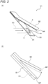
- Fig. 2 is a configuration diagram showing the details of the first check valve V1 shown in Fig. 1 , Fig. 2(a) shows a perspective view, and Fig. 2(b) shows a side view.
- a plate material is illustrated to be thicker than that of Fig. 2(a) .
- the first check valve V1 is provided, for example, so as to be able to open and close a terminal end E (downstream end) of the first vapor refrigerant flow path R1, and includes two base materials B1 and B2 and an operation plate MP.
- the two base materials B1 and B2 are plate materials in a state of being separated from each other by rotation at an angle ⁇ .
- the first base material B1 is formed with an opening O1 having a size corresponding to the diameter of the first vapor refrigerant flow path R1, and the opening O1 is in a state of being connected to the terminal end E of the first vapor refrigerant flow path R1.
- the second base material B2 is a plate material without an opening. It is noted that the second base material B2 may have an opening or the like.
- the operation plate MP is a plate material in a state of contacting the first base material B1 and closing the opening O1 of the first base material B1 in its basic state.
- pressure in the regenerative absorber 10 is increased by discharge of a vapor refrigerant, which causes a pressure difference between the regenerative absorber 10 and the condenser 20.
- the operation plate MP is separated from the first base material B1 by the pressure difference therebetween and rotated (contacts) toward the second base material B2.
- the first check valve V1 is in an open state during the day.
- the regenerative absorber 10 is not heated and the pressure difference does not occur.
- the first check valve V1 is in a closed state. That is, the first check valve V1 has a function of preventing a liquid refrigerant in the condenser 20 from flowing back into the regenerative absorber 10 in the evening and at night or preventing the liquid refrigerant from being vaporized and flowing back thereinto to be absorbed again by the absorbent liquid or the adsorbent agent.
- the condenser 20 introduces a vapor refrigerant from the regenerative absorber 10 and liquefies the vapor refrigerant into a liquid refrigerant.
- This condenser 20 is provided on one surface side of the panel exposed to sunlight.
- the second portion P2 on the one surface side of the panel corresponding to the condenser 20 is subjected to processing so as to have a solar reflectance of 80% or more, and more preferably, is subjected to processing so as to have a solar reflectance of 80% or more and a far-infrared emissivity of 80% or more (refer to Fig. 1(a) ).
- the condenser 20 is maintained in a temperature range of, for example, about 40°C to 50°C during the day, and can condense the vapor refrigerant.
- White enamel processing is an example of the above-described processing capable of obtaining the solar reflectance of 80% or more and the far-infrared emissivity of 80% or more, and in the present embodiment, the second portion P2 is subjected to the white enamel processing.
- a black enamel and a white enamel are applied to one surface side which becomes the same surface of the main body portion 1a. Therefore, both black and white enamel glazes are applied to one surface side and then simultaneously fired, thereby making it possible to perform two types of processing.
- the liquid refrigerant flow path R2 is a flow path that connects the condenser 20 to the evaporator 30.
- the liquid refrigerant flow path R2 is provided so as to be exposed to the outside from the panel-shaped main body portion 1a, but is not limited thereto.
- the liquid refrigerant flow path R2 may be housed and provided in the main body portion 1a.
- the first temperature control valve HV1 is a valve that is opened and closed depending on the ambient temperature, and is provided for the liquid refrigerant flow path R2.
- Fig. 3 is a configuration diagram showing the details of the first temperature control valve HV1 shown in Fig. 1 , Fig. 3(a) shows a perspective view, and Fig. 3(b) shows a side view. It is noted that, in Fig. 3(b) , for the sake of illustration, a plate material is illustrated to be thicker than that of Fig. 3(a) .
- the first temperature control valve HV1 is provided, for example, so as to be able to open and close a starting end S (upstream end) of the liquid refrigerant flow path R2, and includes two base materials HB1 and HB2, a temperature magnet TM, and an operation plate HMP.
- the two base materials HB1 and HB2 are plate materials in a state of being separated from each other by rotation at an angle ⁇ .
- the first base material HB1 is formed with an opening O2 having a size corresponding to the diameter of the liquid refrigerant flow path R2, and the opening O2 is in a state of being connected to the starting end S of the liquid refrigerant flow path R2.
- the second base material HB2 is a plate material without an opening. It is noted that the second base material HB2 may have an opening or the like.
- the temperature magnet TM is provided on the second base material HB2, and is formed of a permanent magnet TM1, a temperature-sensitive ferrite TM2, and a soft iron yoke TM3.
- the temperature-sensitive ferrite TM2 becomes a non-magnetic body at the Curie temperature (specific temperature (for example, 40°C)) or higher, and becomes a magnetic body below the Curie temperature.
- This temperature-sensitive ferrite TM2 is interposed between the permanent magnet TM1 and the soft iron yoke TM3. Therefore, the temperature magnet TM causes a magnetic force thereof to act on the surroundings when the temperature is lower than the specific temperature, and does not cause the magnetic force to act on the surroundings when the temperature reaches the specific temperature or higher.
- the operation plate HMP is a plate material made of a magnetic body, and is in a state of contacting the first base material B1 and closing the starting end S of the liquid refrigerant flow path R2 in its basic state.
- the temperature magnet TM since the temperature inside the condenser 20 is maintained at 40°C or higher during the day, the temperature magnet TM does not exert a magnetic force. Therefore, the operation plate HMP is in a state of contacting the first base material HB1 and closing the liquid refrigerant flow path R2.
- the temperature magnet TM causes a magnetic force thereof to act on the surroundings. Therefore, the operation plate HMP made of the magnetic body is separated from the first base material HB1, and as such the liquid refrigerant flow path R2 is in the state of being opened.
- the second check valve (first vapor refrigerant check valve) V2 is provided in the liquid refrigerant flow path R2 and prevents a vapor refrigerant from flowing backwards from the evaporator 30 into the condenser 20 (refer to Fig. 1(b) ).
- the second check valve V2 is similar to the first check valve V1, and is provided so as to be able to open and close the terminal end of the liquid refrigerant flow path R2.
- the second check valve V2 includes two base material and an operation plate, and is configured to be opened and closed depending on a pressure difference.
- the evaporator 30 is provided on the other surface side (indoor side) that is not exposed to sunlight, and evaporates the liquid refrigerant from the condenser 20 to take away evaporation heat from the other surface side of the panel, thereby performing a cooling effect.
- the inside of the evaporator 30 is, for example, in a vacuum state, so that even if a liquid refrigerant is at room temperature, the liquid refrigerant can evaporate. Therefore, the liquid refrigerant from the condenser 20 evaporates in the evaporator 30 and cools the other surface side.
- the second vapor refrigerant flow path (vapor refrigerant flow path) R3 is a flow path that connects the evaporator 30 to the regenerative absorber 10.
- the second vapor refrigerant flow path R3 is provided so as to be exposed to the outside from the panel-shaped main body portion 1a, but is not limited thereto.
- the second vapor refrigerant flow path R3 may be housed and provided in the main body portion 1a.
- the second temperature control valve HV2 is a valve that is opened and closed depending on the ambient temperature, and is provided in the second vapor refrigerant flow path R3.
- the second temperature control valve HV2 is the same as the first temperature control valve HV1, and, for example, is provided so as to be able to open and close the starting end of the second vapor refrigerant flow path R3.
- the second temperature control valve HV2 includes two base materials, a temperature magnet, and an operation plate.
- the two base materials, the temperature magnet, and the operation plate are the same as those of the first temperature control valve HV1, but a combination of the Curie temperature of the temperature-sensitive ferrite and the permanent magnet, the temperature-sensitive ferrite, and the soft iron yoke is different.
- the Curie temperature of the temperature-sensitive ferrite in the second temperature control valve HV2 is set to about 23°C (specific temperature).
- the second temperature control valve HV2 opens the second vapor refrigerant flow path R3 when the ambient temperature is 23°C or higher, and closes the second vapor refrigerant flow path R3 when the ambient temperature is below 23°C.
- the third check valve (second vapor refrigerant check valve) V3 is provided in the second vapor refrigerant flow path R3 and prevents a vapor refrigerant from flowing backwards from the regenerative absorber 10 into the evaporator 30.
- This third check valve V3 is similar to the first check valve V1, and is provided to so as to be able to open and close the terminal end of the second vapor refrigerant flow path R3.
- This third check valve V3 includes two base materials and an operation plate, and is configured to be opened and closed depending on a pressure difference.
- any one or more of the flow paths R1 to R3 may not be a tubular shape, and may be simply configured to secure a passage for a vapor refrigerant or a liquid refrigerant.
- the latent heat storage material 40 has a phase change temperature (melting point and freezing point) within a specific temperature range (for example, about 23°C).
- a specific temperature range for example, about 23°C.
- the latent heat storage material 40 is provided farther on the other surface side of the panel than the evaporator 30. For this reason, for example, in a case where the air-conditioning panel 1 is used as a building material, when the room temperature is equal to or higher than the specific temperature range, the room is cooled by the latent heat storage material 40, and as such the evaporator 30 functions as a device that takes away heat from the latent heat storage material 40 and solidifies the heat.
- the heat insulating cover 50 is a light-transmissive film material that covers the first portion P1, and corresponds to, for example, an ethylene tetra fluoro ethylene (ETFE) film.
- ETFE ethylene tetra fluoro ethylene
- a black enamel is applied to the first portion P1 corresponding to the regenerative absorber 10, and a solar absorptivity is set to 80% or more.
- the regenerative absorber 10 is heated to, for example, 100°C or higher, so that an absorbent liquid and an adsorbent agent in the regenerative absorber 10 discharge a vapor refrigerant. The discharge of the vapor refrigerant increases pressure in the regenerative absorber 10 and generates a pressure difference between the regenerative absorber 10 and the condenser 20.
- the first check valve V1 provided in the first vapor refrigerant flow path R1 becomes in an open state, and as such the vapor refrigerant passes through the first vapor refrigerant flow path R1 and reaches the condenser 20.
- the condenser 20 even if one surface side of the panel of the air-conditioning panel 1 is exposed to sunlight during the day, a white enamel is applied to the second portion P2, thereby obtaining a solar reflectance of 80% or more and a far-infrared emissivity of 80% or more. Therefore, the inside of the condenser 20 is maintained at about 40°C to 50°C. Accordingly, the vapor refrigerant from the regenerative absorber 10 is liquefied in the condenser 20 and becomes a liquid refrigerant.
- the first temperature control valve HV1 maintains a closed state. Therefore, the liquid refrigerant is accumulated in the condenser 20 without moving to the evaporator 30.
- the third check valve V3 is closed due to a high pressure in the regenerative absorber 10, and the evaporator 30 becomes in a non-functioning state.
- regeneration is performed in the regenerative absorber 10 during the day, and the liquid refrigerant is accumulated in the condenser 20. It is noted that, when the room temperature is 23°C or higher during the day, the interior of a room is cooled by the latent heat storage material 40.
- the temperature of the condenser 20 is lowered.
- the first temperature control valve HV1 of the liquid refrigerant flow path R2 is opened.
- the second check valve V2 is also opened, and the liquid refrigerant moves to the evaporator 30.
- the inside of the evaporator 30 is in a vacuum state. Therefore, the liquid refrigerant in the evaporator 30 evaporates at night.
- the second temperature control valve HV2 is in an open state.
- the third check valve V3 is also in an open state, and the vapor refrigerant generated in the evaporator 30 reaches the regenerative absorber 10.
- the vapor refrigerant that has reached the regenerative absorber 10 is absorbed by an absorbent liquid or an adsorbent agent in the regenerative absorber 10.
- a black enamel is applied to the first portion P1, and a far-infrared emissivity is set to 80% or more. Therefore, absorbed heat is suitably discharged.
- the latent heat storage material 40 is cooled by evaporation in the evaporator 30. Therefore, even if the latent heat storage material 40 is in a molten state during the day, the same will be in a solidified state again, and as such a cooling effect to the indoor side will be restored.
- the pressure of the evaporator 30 becomes higher than that of the condenser 20 due to evaporation by the evaporator 30 at night. Therefore, the second check valve V2 becomes in a closed state, thereby preventing the vapor refrigerant from flowing backwards from the evaporator 30 into the condenser 20.
- heat transfer from the latent heat storage material 40 to the liquid refrigerant, which is a liquid is much faster than heat transfer from the indoor air to the latent heat storage material 40. Therefore, even if the latent heat storage material 40 capable of cooling the interior of a room for several days is mounted on the air-conditioning panel 1, when evaporation is performed in the evaporator 30 for several hours at night, almost all of the latent heat storage material 40 returns to a solid state.
- the air-conditioning panel 1 since the air-conditioning panel 1 according to the present embodiment includes the regenerative absorber 10 having an absorbent liquid or an adsorbent agent that absorbs a vapor refrigerant and discharging the vapor refrigerant by being exposed to sunlight, the air-conditioning panel 1 can perform regeneration by being exposed to sunlight and perform absorption when not exposed to sunlight, and as such a limited area can be effectively utilized without separately providing a regenerator and an absorber.
- the regenerative absorber 10 and the condenser 20 are formed on one surface side of the panel, which is exposed to sunlight, and the evaporator 30 is formed on the other surface side of the panel, which is opposite to the one surface side of the panel, thereby making it possible not only to prevent reduction in the area of the evaporator 30 due to existence of the condenser 20, but also to prevent deterioration in the air-conditioning effect due to discarding of condensation heat.
- the regenerative absorber 10 and the condenser 20 are formed on one surface side of the panel, the one surface side being the side exposed to sunlight, the first portion P1 corresponding to the regenerative absorber 10 is subjected to processing so as to have a solar absorptivity of 80% or more and a far-infrared emissivity of 80% or more, and the second portion P2 corresponding to the condenser 20 is subjected to processing so as to have a solar reflectance of 80% or more, thereby making it possible to achieve a configuration in which regeneration and absorption are performed in the regenerative absorber 10, and deterioration in condensation efficiency in the condenser 20 is suppressed. Therefore, it is possible to solve the problem related to area occupancy and to execute more sufficient performance.
- a black enamel is formed in the first portion P1
- a solar absorptivity of 80% or more and a far-infrared emissivity of 80% or more can be achieved by enamel processing.
- a white enamel is formed in the second portion P2
- a solar reflectance of 80% or more can be achieved by enamel processing.
- the first and second portions P1 and P2 can be formed by simultaneous firing, which can contribute to simplification of a manufacturing process.
- the second check valve V2 is provided to prevent a vapor refrigerant from flowing backwards from the evaporator 30 into the condenser 20, it is possible to prevent the vapor refrigerant generated in the evaporator 30 from returning to the condenser 20 at night and to appropriately send the vapor refrigerant to the regenerative absorber 10. Therefore, it is possible to contribute to performing an appropriate air-conditioning operation.
- the third check valve V3 is provided to prevent a vapor refrigerant from flowing backwards from the regenerative absorber 10 into the evaporator 30, it is possible to prevent the vapor refrigerant generated in the regenerative absorber 10 from moving to the evaporator 30 during the time at which the regenerative absorber 10 is exposed to sunlight during the day and to appropriately send the vapor refrigerant to the condenser 20. Therefore, it is possible to contribute to performing an appropriate air-conditioning operation.
- the latent heat storage material 40 may not be provided when a cooling effect is desired to be achieved only at night.
- first and second temperature control valves HV1 and HV2 using the temperature magnet TM are provided in the present embodiment, the present disclosure is not limited thereto.
- a temperature sensor and a control unit may be further provided, and the first and second temperature control valves HV1 and HV2 may be opened and closed by the control unit according to the temperature detected by the temperature sensor.
Landscapes
- Engineering & Computer Science (AREA)
- Mechanical Engineering (AREA)
- General Engineering & Computer Science (AREA)
- Life Sciences & Earth Sciences (AREA)
- Sustainable Development (AREA)
- Chemical & Material Sciences (AREA)
- Combustion & Propulsion (AREA)
- Physics & Mathematics (AREA)
- Thermal Sciences (AREA)
- Sustainable Energy (AREA)
- Sorption Type Refrigeration Machines (AREA)
- Air Filters, Heat-Exchange Apparatuses, And Housings Of Air-Conditioning Units (AREA)
Applications Claiming Priority (2)
| Application Number | Priority Date | Filing Date | Title |
|---|---|---|---|
| JP2021076053A JP7620491B2 (ja) | 2021-04-28 | 2021-04-28 | 空調パネル |
| PCT/JP2022/014718 WO2022230515A1 (ja) | 2021-04-28 | 2022-03-25 | 空調パネル |
Publications (2)
| Publication Number | Publication Date |
|---|---|
| EP4332464A1 true EP4332464A1 (de) | 2024-03-06 |
| EP4332464A4 EP4332464A4 (de) | 2024-09-25 |
Family
ID=83847988
Family Applications (1)
| Application Number | Title | Priority Date | Filing Date |
|---|---|---|---|
| EP22795432.8A Withdrawn EP4332464A4 (de) | 2021-04-28 | 2022-03-25 | Klimapaneel |
Country Status (6)
| Country | Link |
|---|---|
| US (1) | US12287118B2 (de) |
| EP (1) | EP4332464A4 (de) |
| JP (1) | JP7620491B2 (de) |
| CN (1) | CN117063028A (de) |
| AU (1) | AU2022265118A1 (de) |
| WO (1) | WO2022230515A1 (de) |
Families Citing this family (2)
| Publication number | Priority date | Publication date | Assignee | Title |
|---|---|---|---|---|
| CN120051409A (zh) | 2022-10-13 | 2025-05-27 | 软银集团股份有限公司 | 控制系统、车辆及控制程序 |
| JP7667898B1 (ja) | 2024-05-21 | 2025-04-23 | ポルタパーク株式会社 | 空調パネル |
Family Cites Families (12)
| Publication number | Priority date | Publication date | Assignee | Title |
|---|---|---|---|---|
| JP2002107003A (ja) | 2000-07-24 | 2002-04-10 | Mayekawa Mfg Co Ltd | パネル形吸着式冷凍機 |
| WO2008114266A2 (en) | 2007-03-22 | 2008-09-25 | Ewa Tech Ltd | Apparatus and method for solar cooling and air conditioning |
| DE102009043515A1 (de) | 2009-09-30 | 2011-04-07 | Wolf Beineke | Solarthermisch betriebene Adsorptionskältemaschine zur Raumklimatisierung und Lebensmittelkühlung |
| JP5685485B2 (ja) * | 2011-05-13 | 2015-03-18 | 日立アプライアンス株式会社 | 太陽光熱利用蒸気吸収式冷凍機及び太陽光熱利用システム |
| EP3114415B1 (de) * | 2014-03-07 | 2023-06-28 | Zinniatek Limited | Sonnenenergiedachsystem |
| US9488394B1 (en) | 2015-08-28 | 2016-11-08 | King Fahd University Of Petroleum And Minerals | System and method for continuously operating a solar-powered air conditioner |
| JP6552425B2 (ja) | 2015-09-18 | 2019-07-31 | ポルタパーク株式会社 | 熱交換装置 |
| EP3299759A1 (de) * | 2016-09-21 | 2018-03-28 | Nederlandse Organisatie voor toegepast- natuurwetenschappelijk onderzoek TNO | System und verfahren zur thermochemischen speicherung von energie |
| US10663194B2 (en) * | 2017-02-07 | 2020-05-26 | Adam Peter Plesniak | Modular solar air heater |
| JP6995613B2 (ja) | 2017-12-26 | 2022-01-14 | 矢崎エナジーシステム株式会社 | 回転建具 |
| JP7350434B2 (ja) * | 2019-08-09 | 2023-09-26 | 矢崎エナジーシステム株式会社 | 構造体及びその製造方法 |
| JP7346250B2 (ja) | 2019-11-07 | 2023-09-19 | 日野自動車株式会社 | 内燃機関システムの異常診断装置 |
-
2021
- 2021-04-28 JP JP2021076053A patent/JP7620491B2/ja active Active
-
2022
- 2022-03-25 WO PCT/JP2022/014718 patent/WO2022230515A1/ja not_active Ceased
- 2022-03-25 AU AU2022265118A patent/AU2022265118A1/en not_active Abandoned
- 2022-03-25 EP EP22795432.8A patent/EP4332464A4/de not_active Withdrawn
- 2022-03-25 CN CN202280024230.4A patent/CN117063028A/zh active Pending
-
2023
- 2023-09-22 US US18/473,201 patent/US12287118B2/en active Active
Also Published As
| Publication number | Publication date |
|---|---|
| CN117063028A (zh) | 2023-11-14 |
| AU2022265118A1 (en) | 2023-10-05 |
| WO2022230515A1 (ja) | 2022-11-03 |
| EP4332464A4 (de) | 2024-09-25 |
| JP7620491B2 (ja) | 2025-01-23 |
| US12287118B2 (en) | 2025-04-29 |
| JP2022170136A (ja) | 2022-11-10 |
| US20240011649A1 (en) | 2024-01-11 |
Similar Documents
| Publication | Publication Date | Title |
|---|---|---|
| US12287118B2 (en) | Air-conditioning panel | |
| JP3966044B2 (ja) | 空調装置 | |
| JP2013217631A (ja) | 冷凍サイクル装置 | |
| KR101903108B1 (ko) | 자동차용 히트펌프 | |
| CN103983037B (zh) | 带除霜功能的双级压缩空调系统 | |
| JP4767047B2 (ja) | 空気調和装置 | |
| CN110114234B (zh) | 用于机动车辆的间接可逆空调回路及相应的操作方法 | |
| JP2009264661A (ja) | 空気調和システム | |
| WO2021015270A1 (ja) | 熱管理装置 | |
| WO2019111621A1 (ja) | ヒートポンプシステム | |
| CN107444063B (zh) | 一种车辆热泵空调器及其控制方法 | |
| WO2013088684A1 (ja) | 空気調和機 | |
| WO2019054401A1 (ja) | 冷凍サイクル装置 | |
| KR102644751B1 (ko) | 히트 펌프 사이클 | |
| JP6888280B2 (ja) | 冷凍装置 | |
| CN111595087B (zh) | 冷藏库 | |
| JP2014047955A (ja) | 冷凍サイクル装置 | |
| JP2006232164A (ja) | 車両用空調装置 | |
| JP4158235B2 (ja) | 車両用空調装置 | |
| CN114683809B (zh) | 热泵空调系统和车辆 | |
| JP3464295B2 (ja) | 冷凍冷蔵庫 | |
| JP2004028401A (ja) | 車両用空調装置 | |
| JPH11211261A (ja) | 冷凍装置 | |
| JPH02298771A (ja) | ヒートポンプ式冷凍サイクル装置 | |
| JP2002089934A (ja) | 空気調和機 |
Legal Events
| Date | Code | Title | Description |
|---|---|---|---|
| STAA | Information on the status of an ep patent application or granted ep patent |
Free format text: STATUS: THE INTERNATIONAL PUBLICATION HAS BEEN MADE |
|
| PUAI | Public reference made under article 153(3) epc to a published international application that has entered the european phase |
Free format text: ORIGINAL CODE: 0009012 |
|
| STAA | Information on the status of an ep patent application or granted ep patent |
Free format text: STATUS: REQUEST FOR EXAMINATION WAS MADE |
|
| 17P | Request for examination filed |
Effective date: 20230922 |
|
| AK | Designated contracting states |
Kind code of ref document: A1 Designated state(s): AL AT BE BG CH CY CZ DE DK EE ES FI FR GB GR HR HU IE IS IT LI LT LU LV MC MK MT NL NO PL PT RO RS SE SI SK SM TR |
|
| DAV | Request for validation of the european patent (deleted) | ||
| DAX | Request for extension of the european patent (deleted) | ||
| REG | Reference to a national code |
Ref country code: DE Ref legal event code: R079 Free format text: PREVIOUS MAIN CLASS: F25B0027000000 Ipc: F24F0005000000 |
|
| A4 | Supplementary search report drawn up and despatched |
Effective date: 20240823 |
|
| RIC1 | Information provided on ipc code assigned before grant |
Ipc: F25B 37/00 20060101ALI20240819BHEP Ipc: F25B 27/00 20060101ALI20240819BHEP Ipc: F24F 5/00 20060101AFI20240819BHEP |
|
| STAA | Information on the status of an ep patent application or granted ep patent |
Free format text: STATUS: THE APPLICATION HAS BEEN WITHDRAWN |
|
| 18W | Application withdrawn |
Effective date: 20241030 |