EP4332471A1 - Système et procédé de réfrigération et de conditionnement thermique d'un corps - Google Patents
Système et procédé de réfrigération et de conditionnement thermique d'un corps Download PDFInfo
- Publication number
- EP4332471A1 EP4332471A1 EP22382820.3A EP22382820A EP4332471A1 EP 4332471 A1 EP4332471 A1 EP 4332471A1 EP 22382820 A EP22382820 A EP 22382820A EP 4332471 A1 EP4332471 A1 EP 4332471A1
- Authority
- EP
- European Patent Office
- Prior art keywords
- reservoir
- circuit
- coolant component
- refrigeration
- thermal conditioning
- Prior art date
- Legal status (The legal status is an assumption and is not a legal conclusion. Google has not performed a legal analysis and makes no representation as to the accuracy of the status listed.)
- Pending
Links
Images



Classifications
-
- H—ELECTRICITY
- H05—ELECTRIC TECHNIQUES NOT OTHERWISE PROVIDED FOR
- H05K—PRINTED CIRCUITS; CASINGS OR CONSTRUCTIONAL DETAILS OF ELECTRIC APPARATUS; MANUFACTURE OF ASSEMBLAGES OF ELECTRICAL COMPONENTS
- H05K7/00—Constructional details common to different types of electric apparatus
- H05K7/20—Modifications to facilitate cooling, ventilating, or heating
- H05K7/2029—Modifications to facilitate cooling, ventilating, or heating using a liquid coolant with phase change in electronic enclosures
- H05K7/20327—Accessories for moving fluid, for connecting fluid conduits, for distributing fluid or for preventing leakage, e.g. pumps, tanks or manifolds
-
- F—MECHANICAL ENGINEERING; LIGHTING; HEATING; WEAPONS; BLASTING
- F25—REFRIGERATION OR COOLING; COMBINED HEATING AND REFRIGERATION SYSTEMS; HEAT PUMP SYSTEMS; MANUFACTURE OR STORAGE OF ICE; LIQUEFACTION SOLIDIFICATION OF GASES
- F25D—REFRIGERATORS; COLD ROOMS; ICE-BOXES; COOLING OR FREEZING APPARATUS NOT OTHERWISE PROVIDED FOR
- F25D17/00—Arrangements for circulating cooling fluids; Arrangements for circulating gas, e.g. air, within refrigerated spaces
- F25D17/02—Arrangements for circulating cooling fluids; Arrangements for circulating gas, e.g. air, within refrigerated spaces for circulating liquids, e.g. brine
-
- F—MECHANICAL ENGINEERING; LIGHTING; HEATING; WEAPONS; BLASTING
- F25—REFRIGERATION OR COOLING; COMBINED HEATING AND REFRIGERATION SYSTEMS; HEAT PUMP SYSTEMS; MANUFACTURE OR STORAGE OF ICE; LIQUEFACTION SOLIDIFICATION OF GASES
- F25C—PRODUCING, WORKING OR HANDLING ICE
- F25C1/00—Producing ice
- F25C1/04—Producing ice by using stationary moulds
-
- F—MECHANICAL ENGINEERING; LIGHTING; HEATING; WEAPONS; BLASTING
- F25—REFRIGERATION OR COOLING; COMBINED HEATING AND REFRIGERATION SYSTEMS; HEAT PUMP SYSTEMS; MANUFACTURE OR STORAGE OF ICE; LIQUEFACTION SOLIDIFICATION OF GASES
- F25D—REFRIGERATORS; COLD ROOMS; ICE-BOXES; COOLING OR FREEZING APPARATUS NOT OTHERWISE PROVIDED FOR
- F25D31/00—Other cooling or freezing apparatus
- F25D31/005—Combined cooling and heating devices
-
- H—ELECTRICITY
- H05—ELECTRIC TECHNIQUES NOT OTHERWISE PROVIDED FOR
- H05K—PRINTED CIRCUITS; CASINGS OR CONSTRUCTIONAL DETAILS OF ELECTRIC APPARATUS; MANUFACTURE OF ASSEMBLAGES OF ELECTRICAL COMPONENTS
- H05K7/00—Constructional details common to different types of electric apparatus
- H05K7/20—Modifications to facilitate cooling, ventilating, or heating
- H05K7/2029—Modifications to facilitate cooling, ventilating, or heating using a liquid coolant with phase change in electronic enclosures
- H05K7/20318—Condensers
-
- H—ELECTRICITY
- H05—ELECTRIC TECHNIQUES NOT OTHERWISE PROVIDED FOR
- H05K—PRINTED CIRCUITS; CASINGS OR CONSTRUCTIONAL DETAILS OF ELECTRIC APPARATUS; MANUFACTURE OF ASSEMBLAGES OF ELECTRICAL COMPONENTS
- H05K7/00—Constructional details common to different types of electric apparatus
- H05K7/20—Modifications to facilitate cooling, ventilating, or heating
- H05K7/2089—Modifications to facilitate cooling, ventilating, or heating for power electronics, e.g. for inverters for controlling motor
- H05K7/20936—Liquid coolant with phase change
-
- F—MECHANICAL ENGINEERING; LIGHTING; HEATING; WEAPONS; BLASTING
- F25—REFRIGERATION OR COOLING; COMBINED HEATING AND REFRIGERATION SYSTEMS; HEAT PUMP SYSTEMS; MANUFACTURE OR STORAGE OF ICE; LIQUEFACTION SOLIDIFICATION OF GASES
- F25C—PRODUCING, WORKING OR HANDLING ICE
- F25C1/00—Producing ice
- F25C1/22—Construction of moulds; Filling devices for moulds
-
- F—MECHANICAL ENGINEERING; LIGHTING; HEATING; WEAPONS; BLASTING
- F25—REFRIGERATION OR COOLING; COMBINED HEATING AND REFRIGERATION SYSTEMS; HEAT PUMP SYSTEMS; MANUFACTURE OR STORAGE OF ICE; LIQUEFACTION SOLIDIFICATION OF GASES
- F25C—PRODUCING, WORKING OR HANDLING ICE
- F25C5/00—Working or handling ice
- F25C5/02—Apparatus for disintegrating, removing or harvesting ice
- F25C5/04—Apparatus for disintegrating, removing or harvesting ice without the use of saws
- F25C5/08—Apparatus for disintegrating, removing or harvesting ice without the use of saws by heating bodies in contact with the ice
-
- F—MECHANICAL ENGINEERING; LIGHTING; HEATING; WEAPONS; BLASTING
- F25—REFRIGERATION OR COOLING; COMBINED HEATING AND REFRIGERATION SYSTEMS; HEAT PUMP SYSTEMS; MANUFACTURE OR STORAGE OF ICE; LIQUEFACTION SOLIDIFICATION OF GASES
- F25C—PRODUCING, WORKING OR HANDLING ICE
- F25C5/00—Working or handling ice
- F25C5/18—Storing ice
- F25C5/182—Ice bins therefor
- F25C5/185—Ice bins therefor with freezing trays
Definitions
- the present invention generally relates to a system and to a method for refrigeration and thermal conditioning of a body, for example, an ice bucket, a battery for an electric vehicle, a magnetic component, etc.
- the invention also relates to a machine for making ice cubes incorporating the mentioned system for refrigeration and thermal conditioning.
- a refrigeration system with a single reservoir which pulls heat out of a battery is known from patent application CN209374610 .
- a cooling TEC module is activated.
- the TEC module is also used for heating the battery.
- an open type constant-temperature water conditioner for charging and swapping stations is known from patent document CN209445648U .
- a water or ethylene glycol reservoir cooled with a compressor similar to the first reservoir of the present invention, is used, although for heating, an electric or infrared heater is used.
- WO2014049179 describes a method and a device for rapid freezing of ice cubes.
- the ice cube defrosting system consists of electrical resistors located on the outer walls of the ice cube housing. These cables and resistors are in contact with the coolant, increasing the risk of a short circuit and negatively affecting the efficiency of the device given that the heating of the ice cube is slower, and given that most of the heat is not transmitted to the ice cube, but rather to the glycol, which is at a lower temperature.
- the embodiments of the present invention provide, according to a first aspect, a system for refrigeration and thermal conditioning of a body, as defined in claim 1.
- the proposed system comprises a body to be refrigerated and thermally conditioned; a first circuit for refrigeration of the body and a second circuit for thermal conditioning of the body.
- the first circuit includes a first reservoir for storage of a liquid coolant component, for example, glycol, among others.
- the first reservoir is for keeping the coolant component at a certain temperature which keeps it cold within a first given temperature range, for example, between -20oC and -30oC.
- the first circuit includes a first pump for pumping the cold coolant component from inside the first reservoir to at least one portion of the body, and for returning the cold coolant component to the first reservoir once the coolant component has been applied to said portion of the body, which is at least one in number.
- the second circuit also includes a second reservoir for storage of a liquid coolant component, for example, glycol, among others.
- the second reservoir is configured for maintaining the coolant component at a certain temperature that keeps it hot within a second given temperature range, depending on the type of application.
- the second circuit includes a second pump for pumping the hot coolant component from inside the second reservoir to the portion of the body, and for returning the hot coolant component to the second reservoir once the coolant component has been applied, for a given period of time, to the portion of the body.
- the first circuit and the second circuit are configured for operating in an alternating manner during the refrigeration and subsequent thermal conditioning.
- Embodiments of the present invention also provide, according to a second aspect, a method for refrigeration and thermal conditioning of a body.
- the method comprises: refrigerating a body by means of applying a cold liquid coolant component in at least one portion of the body, wherein the cold coolant component is applied by means of a first circuit of a system for refrigeration and thermal conditioning, said first circuit comprising: a first reservoir for storage of the coolant component at a certain temperature which keeps it cold within a first given temperature range; and a first pump for pumping the cold coolant component from inside the first reservoir to the portion of the body, which is at least one in number; returning the cold coolant component to the first reservoir once it has been applied to said portion of the body; thermally conditioning the body by means of applying a hot liquid coolant component in said portion of the body, wherein the hot coolant component is applied by means of a second circuit of the system for refrigeration, said second circuit comprising: a second reservoir for storage of the coolant component at a certain temperature which keeps it hot within a second
- the body to be refrigerated and thermally conditioned may comprise: a battery for an electric vehicle, a power electronic component such as a transformer or a capacitor, an ice bucket with a series of trays for making ice cubes, etc.
- the system further comprises a condensation unit, and the second circuit comprises a heat recovery element for recovering heat from the thermal energy generated in the condensation unit. This thermal energy is used to heat the coolant component at said second given temperature range.
- the body comprises an ice bucket with a series of trays for making ice cubes, with a section of the first circuit being in thermal contact with walls of the trays and/or extending between gaps in the trays.
- the first circuit further comprises, a pre-cooling reservoir for collecting water melted from the body due to thermal conditioning.
- the pre-cooling reservoir incorporates a detachable cover with slots which block the passage of the ice cubes; and a body with an interior comprising a plurality of fins to facilitate a heat exchange with the melted water and a double bottom through which the coolant component coming from the first reservoir is introduced.
- the system also includes a storage bin, arranged below the pre-cooling reservoir, comprising a perforated base, a water inlet, a water outlet, a cold coolant component inlet and a cold coolant component outlet.
- a storage bin arranged below the pre-cooling reservoir, comprising a perforated base, a water inlet, a water outlet, a cold coolant component inlet and a cold coolant component outlet.
- the mentioned bin is part of the pre-cooling reservoir itself.
- the ice bucket is fixed and comprises a lower base or portion adapted and configured for opening through at least one side joint of the lower base or portion, allowing the ice cubes made to be discharged.
- the system for refrigeration and thermal conditioning includes one or more electrovalves and/or one or more temperature sensors.
- an automated control system preferably with a display, and wireless and/or network connectivity, is also included.
- a third aspect of the invention provides a machine for making ice cubes that comprises the system for refrigeration and thermal conditioning of the first aspect of the invention, with the body to be refrigerated and thermally conditioned being an ice bucket with a series of trays for making ice cubes.
- the system for refrigeration further comprises a condensation unit; the first circuit further comprises a pre-cooling reservoir for collecting water melted from the body due to thermal conditioning; and the second circuit further comprises a heat recovery element for recovering heat from a thermal energy generated in the condensation unit, with said thermal energy being used to heat the coolant component.
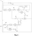
- Figs. 1 and 2 shown therein are two embodiments of the components and connections of the proposed system 1 for refrigeration and thermal conditioning of a body, for example, an ice bucket 101 with a series of trays for making ice cubes (see Fig. 3 for one example), a battery for an electric vehicle (not illustrated), a magnetic component (see Fig. 8 for an example).
- a body for example, an ice bucket 101 with a series of trays for making ice cubes (see Fig. 3 for one example), a battery for an electric vehicle (not illustrated), a magnetic component (see Fig. 8 for an example).
- the system 1 comprises two circuits which can operate in an alternating manner during refrigeration and thermal conditioning of the body 100.
- the first circuit 1C is used for refrigerating the body 100 and comprises a cold coolant reservoir, or first reservoir, 10; a cold coolant pump, or first pump, 11; a cold-body coolant non-return valve 72; and body-cold coolant electrovalve 61.
- the second circuit 2C is used for thermally conditioning, or tempering, the body 100 and comprises a hot coolant reservoir, or second reservoir, 20; a hot coolant pump, or second pump, 21; a hot coolant-body non-return valve 74; a hot coolant-body electrovalve 64; and a body-hot coolant electrovalve 65.
- the second circuit 2C also comprises a heat recovery element 51 for recovering the heat expelled by a condensation unit 50 (see Fig. 7 for an example) with its corresponding electrovalve 66 and non-return valve 75.
- the system 1 further comprises a pre-cooling reservoir 40 for collecting water melted from the body 100 due to thermal conditioning, with its corresponding cold water pump 41 and a cold water-body non-return valve 73; a cold coolant-cold water electrovalve 63 between the cold coolant pump 11 and the pre-cooling reservoir 40; a cold water-cold coolant non-return valve 71; and a water reservoir 30 with a connection to the pre-cooling reservoir 40 by means of a water intake-cold water reservoir electrovalve 62.
- FIGs. 3 and 4 show an embodiment of the proposed machine for making ice cubes.
- the machine incorporates the system 1 for refrigeration and thermal conditioning.
- the machine comprises, attached to a fixing panel 80: an ice bucket 101; the pre-cooling reservoir 40; a storage bin 70; the condensation unit 50; the heat recovery element 51; the two cold and hot coolant reservoirs 10, 20, respectively, with their corresponding pumps 11, 21 and electrovalves 60 (including electrovalves 61-66); an electromechanical component 67; and temperature sensors 91, which allow the condition of the machine to be known.
- the electrical components of the machine for example, relays, power supplies, automated control system, etc., are located in an isolated enclosure intended to be installed inside the machine, thereby avoiding short circuits caused by possible leaks or dripping of frost.
- the ice bucket 101 is tempered, for its defrosting, using the hot coolant, for example, glycol, among others, instead of by means of using electrical resistors on the outer faces of the ice cube housing.
- the cold coolant can be discharged minimizing the thermal conditioning time (about 1 minute).
- the heating of the hot coolant is performed by means of the heat recovery element 51 which recovers the heat expelled by the condensation unit 50.
- the heat expelled by the condensation unit 50 is thereby utilized, reducing the use of electrical resistors for heating the coolants, and expulsion of heat to the exterior is reduced.
- the pre-cooling reservoir 40 has a positive impact on total water utilization, on better energy utilization, and on improved machine performance.
- the pre-cooling reservoir 40 allows all the water to be utilized, avoiding the draining of water that thaws during defrosting.
- the water melted during defrosting is colder than the water in the cold water reservoir 30 (usually at room temperature), so utilizing it also represents energy savings.
- Fig. 5 shows an embodiment of the ice bucket 101.
- the ice bucket 101 includes a coolant inlet 102, a coolant outlet 103, a motor 104 and an opening mechanism 105.
- the ice bucket 101 also includes a lower portion 106 with sealing gaskets 107. The lower portion 106 can open and close, thereby allowing the ice cubes made to be discharged into the ice bucket 101.
- Fig. 6 shows an embodiment of the pre-cooling reservoir 40
- Fig. 7 shows an embodiment of the storage bin 70. It should be mentioned that although in the embodiments described above, both elements are separate, in other embodiments, these elements can be part of a single element that implements both functions, thereby reducing the size and cost of the machine, as an element is eliminated; refrigeration of the storage bin 70 is allowed, improving the conservation of the ice cube; and if the stored ice cubes partially melt, the liquid water will be utilized.
- the pre-cooling reservoir 40 illustrated in Fig. 6 comprises a cover 42 with slots which prevent the passage of the ice cubes made into the ice bucket 101, and a body 43 with an interior comprising a double bottom into which the cold coolant component is introduced through the inlet 45.
- a series of fins 44 facilitating the heat exchange with the melted water, and also holes 46 for sensors, are included in the interior of the pre-cooling reservoir 40.
- the storage bin 70 in turn, comprises a perforated base 71, a water inlet 72, a water outlet 73, a cold coolant inlet 74 and a cold coolant outlet 75.
- the proposed machine for making ice cubes also incorporates an automated control system with a display and with wireless and/or network IP connectivity. This allows the parameters of the machine to be modified remotely, maintenance tasks to be performed remotely, and scheduling of the various operating modes to be performed remotely.
- the machine can also incorporate various operating modes, such as:
- Fig. 8 illustrates an example of a ferromagnetic core 201 including a winding 202 and a respective coolant inlet 203 and a respective coolant outlet 204.
Landscapes
- Engineering & Computer Science (AREA)
- Microelectronics & Electronic Packaging (AREA)
- Physics & Mathematics (AREA)
- Thermal Sciences (AREA)
- Mechanical Engineering (AREA)
- General Engineering & Computer Science (AREA)
- Chemical & Material Sciences (AREA)
- Combustion & Propulsion (AREA)
- Devices That Are Associated With Refrigeration Equipment (AREA)
Priority Applications (2)
| Application Number | Priority Date | Filing Date | Title |
|---|---|---|---|
| EP22382820.3A EP4332471A1 (fr) | 2022-09-02 | 2022-09-02 | Système et procédé de réfrigération et de conditionnement thermique d'un corps |
| US18/450,764 US20240081024A1 (en) | 2022-09-02 | 2023-08-16 | System and method for refrigeration and thermal conditioning of a body |
Applications Claiming Priority (1)
| Application Number | Priority Date | Filing Date | Title |
|---|---|---|---|
| EP22382820.3A EP4332471A1 (fr) | 2022-09-02 | 2022-09-02 | Système et procédé de réfrigération et de conditionnement thermique d'un corps |
Publications (1)
| Publication Number | Publication Date |
|---|---|
| EP4332471A1 true EP4332471A1 (fr) | 2024-03-06 |
Family
ID=83232755
Family Applications (1)
| Application Number | Title | Priority Date | Filing Date |
|---|---|---|---|
| EP22382820.3A Pending EP4332471A1 (fr) | 2022-09-02 | 2022-09-02 | Système et procédé de réfrigération et de conditionnement thermique d'un corps |
Country Status (2)
| Country | Link |
|---|---|
| US (1) | US20240081024A1 (fr) |
| EP (1) | EP4332471A1 (fr) |
Citations (14)
| Publication number | Priority date | Publication date | Assignee | Title |
|---|---|---|---|---|
| US3888303A (en) * | 1972-10-04 | 1975-06-10 | Stephen F Skala | Thermal exchange fluid preparation of foods |
| US4173993A (en) * | 1972-10-04 | 1979-11-13 | Skala Stephen F | Domestic appliance system with thermal exchange fluid |
| US4246955A (en) * | 1972-10-04 | 1981-01-27 | Skala Stephen F | Pressure cooking appliance with thermal exchange fluid |
| US20110204655A1 (en) * | 2010-02-19 | 2011-08-25 | Dynasep Llc | Energy storage systems |
| WO2014049179A1 (fr) | 2012-09-28 | 2014-04-03 | Manuel Estrada Amo | Congélation rapide de cubes de glace, procédé, dispositif, produit et utilisations correspondants |
| EP2733445A2 (fr) | 2012-11-16 | 2014-05-21 | Whirlpool Corporation | Libération de glaçons et congélation rapide utilisant un appareil et des procédés d'échange de fluides |
| US20140150460A1 (en) * | 2012-12-03 | 2014-06-05 | Whirlpool Corporation | Apparatus with ice maker |
| US9291381B2 (en) | 2012-11-13 | 2016-03-22 | William G. Nelson | Clear ice making machine |
| US10132552B2 (en) | 2015-06-17 | 2018-11-20 | Dongbu Daewoo Electronics Corporation | Refrigerator having refrigeration system and ice maker within door and drain duct from ice maker to dispenser excess water tray |
| CN209374610U (zh) | 2018-10-18 | 2019-09-10 | 瞿志刚 | 新能源电动汽车电池综合热管理系统 |
| US20190285327A1 (en) * | 2018-03-19 | 2019-09-19 | Emerson Climate Technologies, Inc. | Ice Maker And Method Of Making And Harvesting Ice |
| CN209445648U (zh) | 2018-12-11 | 2019-09-27 | 中山市艾特网能技术有限公司 | 一种充换电站的开式恒温水空调器 |
| US10480842B2 (en) | 2017-07-07 | 2019-11-19 | Bsh Home Appliances Corporation | Compact ice making system for slimline ice compartment |
| US20200217572A1 (en) * | 2019-01-07 | 2020-07-09 | Roni Shafir | Ice maker |
Family Cites Families (5)
| Publication number | Priority date | Publication date | Assignee | Title |
|---|---|---|---|---|
| US9731578B2 (en) * | 2014-10-21 | 2017-08-15 | Atieva, Inc. | EV multi-mode thermal management system |
| JP6398764B2 (ja) * | 2015-02-06 | 2018-10-03 | 株式会社デンソー | 車両用熱管理システム |
| US10252597B2 (en) * | 2017-08-01 | 2019-04-09 | Gm Global Technology Llc | Joint active thermal management system and control logic for hybrid and electric vehicles |
| US11338647B1 (en) * | 2018-08-27 | 2022-05-24 | Apple Inc. | Vehicle thermal system |
| KR102896185B1 (ko) * | 2020-08-13 | 2025-12-04 | 현대자동차 주식회사 | 차량용 히트펌프 시스템 |
-
2022
- 2022-09-02 EP EP22382820.3A patent/EP4332471A1/fr active Pending
-
2023
- 2023-08-16 US US18/450,764 patent/US20240081024A1/en active Pending
Patent Citations (14)
| Publication number | Priority date | Publication date | Assignee | Title |
|---|---|---|---|---|
| US4173993A (en) * | 1972-10-04 | 1979-11-13 | Skala Stephen F | Domestic appliance system with thermal exchange fluid |
| US4246955A (en) * | 1972-10-04 | 1981-01-27 | Skala Stephen F | Pressure cooking appliance with thermal exchange fluid |
| US3888303A (en) * | 1972-10-04 | 1975-06-10 | Stephen F Skala | Thermal exchange fluid preparation of foods |
| US20110204655A1 (en) * | 2010-02-19 | 2011-08-25 | Dynasep Llc | Energy storage systems |
| WO2014049179A1 (fr) | 2012-09-28 | 2014-04-03 | Manuel Estrada Amo | Congélation rapide de cubes de glace, procédé, dispositif, produit et utilisations correspondants |
| US9291381B2 (en) | 2012-11-13 | 2016-03-22 | William G. Nelson | Clear ice making machine |
| EP2733445A2 (fr) | 2012-11-16 | 2014-05-21 | Whirlpool Corporation | Libération de glaçons et congélation rapide utilisant un appareil et des procédés d'échange de fluides |
| US20140150460A1 (en) * | 2012-12-03 | 2014-06-05 | Whirlpool Corporation | Apparatus with ice maker |
| US10132552B2 (en) | 2015-06-17 | 2018-11-20 | Dongbu Daewoo Electronics Corporation | Refrigerator having refrigeration system and ice maker within door and drain duct from ice maker to dispenser excess water tray |
| US10480842B2 (en) | 2017-07-07 | 2019-11-19 | Bsh Home Appliances Corporation | Compact ice making system for slimline ice compartment |
| US20190285327A1 (en) * | 2018-03-19 | 2019-09-19 | Emerson Climate Technologies, Inc. | Ice Maker And Method Of Making And Harvesting Ice |
| CN209374610U (zh) | 2018-10-18 | 2019-09-10 | 瞿志刚 | 新能源电动汽车电池综合热管理系统 |
| CN209445648U (zh) | 2018-12-11 | 2019-09-27 | 中山市艾特网能技术有限公司 | 一种充换电站的开式恒温水空调器 |
| US20200217572A1 (en) * | 2019-01-07 | 2020-07-09 | Roni Shafir | Ice maker |
Also Published As
| Publication number | Publication date |
|---|---|
| US20240081024A1 (en) | 2024-03-07 |
Similar Documents
| Publication | Publication Date | Title |
|---|---|---|
| EP2844924B1 (fr) | Système de climatisation ayant un matériau à changement de phase surrefroidi | |
| US6094925A (en) | Crossover warm liquid defrost refrigeration system | |
| CN108284725B (zh) | 新能源汽车分布式驱动智能化热管理系统 | |
| EP2766668B1 (fr) | Stockage d'énergie thermique dans un système de compresseur frigorifique | |
| EP2778574B1 (fr) | Système de refroidissement de réfrigérateur possédant une boucle de refroidissement secondaire | |
| JP2008514895A (ja) | 逆ペルチェ除霜システム | |
| EP0601875A1 (fr) | Procédé et dispositif pour sous-refroidir des circuits à réfrigérant liquide | |
| EP0505315A1 (fr) | Contrôle de dégivrage | |
| EP1872077B1 (fr) | Conditionneur d'air a stockage thermique | |
| CN110112509B (zh) | 电池包加热设备、储热设备以及电动汽车 | |
| US6263686B1 (en) | Defrost control method and apparatus | |
| US5339644A (en) | Defrost system for refrigeration apparatus | |
| US20060037340A1 (en) | Modularized high efficiency cooling device in a cooling mechanism | |
| CN102353210A (zh) | 冰箱及其制冷方法和用于冰箱的速冷装置 | |
| EP4332471A1 (fr) | Système et procédé de réfrigération et de conditionnement thermique d'un corps | |
| EP4325145A1 (fr) | Dégivrage de pompe à chaleur | |
| EP2678612B1 (fr) | Système de climatisation avec stockage de glace | |
| EP1794516B1 (fr) | Systeme de stockage d'energie thermique et de refroidissement a isolation secondaire par refrigerant | |
| CN102322702B (zh) | 冰箱及其制冷系统 | |
| CN206358015U (zh) | 一种集成式汽车蓄电池恒温系统 | |
| CN203402039U (zh) | 冷藏拖车制冷机组 | |
| CN203893476U (zh) | 用于冰箱的制冷系统及冰箱 | |
| CN112050350B (zh) | 一种用于空调除霜的控制方法、控制装置及空调 | |
| CN112050358B (zh) | 一种用于空调除霜的控制方法、控制装置及空调 | |
| KR100371682B1 (ko) | 심야전기를 이용한 축열식 복합 냉,난방 시스템 |
Legal Events
| Date | Code | Title | Description |
|---|---|---|---|
| PUAI | Public reference made under article 153(3) epc to a published international application that has entered the european phase |
Free format text: ORIGINAL CODE: 0009012 |
|
| STAA | Information on the status of an ep patent application or granted ep patent |
Free format text: STATUS: THE APPLICATION HAS BEEN PUBLISHED |
|
| AK | Designated contracting states |
Kind code of ref document: A1 Designated state(s): AL AT BE BG CH CY CZ DE DK EE ES FI FR GB GR HR HU IE IS IT LI LT LU LV MC MK MT NL NO PL PT RO RS SE SI SK SM TR |
|
| STAA | Information on the status of an ep patent application or granted ep patent |
Free format text: STATUS: REQUEST FOR EXAMINATION WAS MADE |
|
| 17P | Request for examination filed |
Effective date: 20240723 |
|
| RBV | Designated contracting states (corrected) |
Designated state(s): AL AT BE BG CH CY CZ DE DK EE ES FI FR GB GR HR HU IE IS IT LI LT LU LV MC MK MT NL NO PL PT RO RS SE SI SK SM TR |