EP4332526B1 - Dispositif de mesure de température et procédé de mesure de température - Google Patents
Dispositif de mesure de température et procédé de mesure de température Download PDFInfo
- Publication number
- EP4332526B1 EP4332526B1 EP21944144.1A EP21944144A EP4332526B1 EP 4332526 B1 EP4332526 B1 EP 4332526B1 EP 21944144 A EP21944144 A EP 21944144A EP 4332526 B1 EP4332526 B1 EP 4332526B1
- Authority
- EP
- European Patent Office
- Prior art keywords
- image
- target
- thermal infrared
- unit
- distance
- Prior art date
- Legal status (The legal status is an assumption and is not a legal conclusion. Google has not performed a legal analysis and makes no representation as to the accuracy of the status listed.)
- Active
Links
Images


Classifications
-
- G—PHYSICS
- G01—MEASURING; TESTING
- G01J—MEASUREMENT OF INTENSITY, VELOCITY, SPECTRAL CONTENT, POLARISATION, PHASE OR PULSE CHARACTERISTICS OF INFRARED, VISIBLE OR ULTRAVIOLET LIGHT; COLORIMETRY; RADIATION PYROMETRY
- G01J5/00—Radiation pyrometry, e.g. infrared or optical thermometry
- G01J5/48—Thermography; Techniques using wholly visual means
-
- G—PHYSICS
- G01—MEASURING; TESTING
- G01J—MEASUREMENT OF INTENSITY, VELOCITY, SPECTRAL CONTENT, POLARISATION, PHASE OR PULSE CHARACTERISTICS OF INFRARED, VISIBLE OR ULTRAVIOLET LIGHT; COLORIMETRY; RADIATION PYROMETRY
- G01J5/00—Radiation pyrometry, e.g. infrared or optical thermometry
- G01J5/0022—Radiation pyrometry, e.g. infrared or optical thermometry for sensing the radiation of moving bodies
- G01J5/0025—Living bodies
-
- G—PHYSICS
- G01—MEASURING; TESTING
- G01J—MEASUREMENT OF INTENSITY, VELOCITY, SPECTRAL CONTENT, POLARISATION, PHASE OR PULSE CHARACTERISTICS OF INFRARED, VISIBLE OR ULTRAVIOLET LIGHT; COLORIMETRY; RADIATION PYROMETRY
- G01J5/00—Radiation pyrometry, e.g. infrared or optical thermometry
- G01J5/02—Constructional details
- G01J5/026—Control of working procedures of a pyrometer, other than calibration; Bandwidth calculation; Gain control
-
- G—PHYSICS
- G01—MEASURING; TESTING
- G01J—MEASUREMENT OF INTENSITY, VELOCITY, SPECTRAL CONTENT, POLARISATION, PHASE OR PULSE CHARACTERISTICS OF INFRARED, VISIBLE OR ULTRAVIOLET LIGHT; COLORIMETRY; RADIATION PYROMETRY
- G01J5/00—Radiation pyrometry, e.g. infrared or optical thermometry
- G01J5/02—Constructional details
- G01J5/0275—Control or determination of height or distance or angle information for sensors or receivers
-
- G—PHYSICS
- G01—MEASURING; TESTING
- G01J—MEASUREMENT OF INTENSITY, VELOCITY, SPECTRAL CONTENT, POLARISATION, PHASE OR PULSE CHARACTERISTICS OF INFRARED, VISIBLE OR ULTRAVIOLET LIGHT; COLORIMETRY; RADIATION PYROMETRY
- G01J5/00—Radiation pyrometry, e.g. infrared or optical thermometry
- G01J5/02—Constructional details
- G01J5/08—Optical arrangements
- G01J5/0859—Sighting arrangements, e.g. cameras
-
- G—PHYSICS
- G01—MEASURING; TESTING
- G01J—MEASUREMENT OF INTENSITY, VELOCITY, SPECTRAL CONTENT, POLARISATION, PHASE OR PULSE CHARACTERISTICS OF INFRARED, VISIBLE OR ULTRAVIOLET LIGHT; COLORIMETRY; RADIATION PYROMETRY
- G01J5/00—Radiation pyrometry, e.g. infrared or optical thermometry
- G01J5/02—Constructional details
- G01J5/08—Optical arrangements
- G01J5/0896—Optical arrangements using a light source, e.g. for illuminating a surface
-
- H—ELECTRICITY
- H04—ELECTRIC COMMUNICATION TECHNIQUE
- H04N—PICTORIAL COMMUNICATION, e.g. TELEVISION
- H04N23/00—Cameras or camera modules comprising electronic image sensors; Control thereof
- H04N23/20—Cameras or camera modules comprising electronic image sensors; Control thereof for generating image signals from infrared radiation only
- H04N23/23—Cameras or camera modules comprising electronic image sensors; Control thereof for generating image signals from infrared radiation only from thermal infrared radiation
-
- G—PHYSICS
- G01—MEASURING; TESTING
- G01J—MEASUREMENT OF INTENSITY, VELOCITY, SPECTRAL CONTENT, POLARISATION, PHASE OR PULSE CHARACTERISTICS OF INFRARED, VISIBLE OR ULTRAVIOLET LIGHT; COLORIMETRY; RADIATION PYROMETRY
- G01J5/00—Radiation pyrometry, e.g. infrared or optical thermometry
- G01J2005/0077—Imaging
Definitions
- the present disclosure relates to a temperature measuring device and a temperature measuring method.
- a thermal image correcting device that is an example of a temperature measuring device and is described in Patent Literature 1 acquires a temperature distribution of an observation target from a thermal image of the observation target captured by a camera.
- US2012307046A1 discloses methods and apparatus, including cameras and computer program products, implementing and using techniques for determining a temperature of a distant object in several temperature measurement points.
- a thermal image sensor measures thermal radiation from a distant object in several thermal measurement points on the object.
- a distance determination device includes an image sensor and calculates a distance to the object in several distance measurement points.
- a thermal image indicating an amount of thermal radiation from each thermal measurement point on the object is captured by the thermal image sensor. Reflected light from the object is captured by the image sensor.
- US7813889B2 discloses an Infrared (IR) thermometer including an IR detector configured to provide an IR emission data representative of a temperature of an area of tissue.
- the IR thermometer also includes one or more secondary sensors configured to provide an IR thermometer positioning data.
- At least one microcomputer is configured to receive the IR thermometer positioning data from one or more secondary sensors.
- the at least one microcomputer is configured to run an algorithm to convert the IR thermometer positioning data to an IR thermometer positioning indication, wherein the IR thermometer positioning indication suggests a direction to move the IR thermometer for a substantially optimal IR detector view of the area of tissue.
- the invention also relates to a guiding means including a positioning sensor and a display of IR thermometer positioning information, and a method for positioning an IR thermometer.
- FUWEN LAI "Thermal image enhancement through the deconvolution methods for low-cost infrared cameras", QIRT JOURNAL - QUANTITATIVE INFRARED THERMOGRAPHY AN INTERNATIONAL JOURNAL ON IR THERMOGRAPHY, 9 May 2018 (2018-05-09), pages 1-17, XP093161062 discloses techniques for enhancing thermal images captured by low-cost infrared cameras through deconvolution methods.
- Patent Literature 1 JP 2020-153737 A
- the above thermal image correcting device using for the above camera a low-cost lens such as a lens whose cost of a material or number of lenses is reduced expands the above thermal image. As a result, there has been a problem that the accuracy of the temperature distribution of the observation target to be acquired deteriorates.
- An object of the present disclosure is to provide a temperature measuring device and a temperature measuring method that improve accuracy of temperatures of measurement targets.
- the temperature measuring device can improve accuracy of temperatures of measurement targets.
- the temperature measuring device according to Embodiment 1 will be described.
- FIG. 1 is a functional block diagram of a temperature measuring device TMD according to Embodiment 1.
- the temperature measuring device TMD includes an IR image acquiring unit 1, an IR illuminating unit 2, a visible light image acquiring unit 3, a processing unit 4, and a measuring unit 5.
- the IR image acquiring unit 1 corresponds to a "thermal infrared image acquiring unit” and a “thermal infrared illumination image acquiring unit”
- the IR illuminating unit 2 corresponds to a "thermal infrared illumination unit”
- the visible light image acquiring unit 3 corresponds to a "visible light image acquiring unit”
- the processing unit 4 corresponds to a "calculating unit” and an “adding unit”
- the measuring unit 5 corresponds to a "measuring unit”.
- IR InfraRed
- the IR image acquiring unit 1 acquires an IR image IRG of the persons JB1 and JB2 by receiving IR light IRK.
- the IR image acquiring unit 1 includes an IR camera (not illustrated) that has sensitivity that comes to a peak in, for example, a mid-infrared wavelength range (3 to 5 ⁇ m) and a far-infrared wavelength range (8 to 15 ⁇ m), and a wavelength selection device (e.g., a narrow band bandpass filter whose wavelength is 10 ⁇ m).
- the IR image acquiring unit 1 When acquiring an IR illumination image IRSG, the IR image acquiring unit 1 selectively receives IR illumination light IRSK using the above wavelength selection device, and thereby eliminates light other than the IR illumination light IRSK such as most of the IR light IRK that is reflected by the persons JB1 and JB2 and influenced by temperatures of the persons JB1 and JB2.
- the IR illuminating unit 2 radiates the IR illumination light IRSK that is infrared light (e.g., above 10 ⁇ m) in a wavelength range for which the IR image acquiring unit 1 has the sensitivity.
- the IR illuminating unit 2 includes, for example, a halogen lamp, a mid-infrared fiber laser, and a quantum cascade laser.
- the IR illuminating unit 2 irradiates the persons JB1 and JB2 with the IR illumination light IRSK, and the IR image acquiring unit 1 acquires the IR illumination image IRSG of the persons JB1 and JB2 by receiving the IR illumination light IRSK reflected by the persons JB1 and JB2.
- the visible light image acquiring unit 3 acquires a visible light image KG of the persons JB1 and JB2.
- the visible light image acquiring unit 3 includes, for example, a visible camera that has sensitivity whose peak comes in a visible light range.
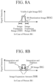
- FIG. 2 illustrates the visible light image KG according to Embodiment 1.
- the person JB1 is captured larger than the person JB2 as illustrated in FIG. 2A .
- the intensity of the visible light KK to be received has a rectangular shape as illustrated in FIG. 2B , that is, there is only the visible light KK from the persons JB1 and JB2, i.e., there are only images GZ1 and GZ2 of the persons JB1 and JB2. Consequently, by scanning the intensity of the visible light KK at a plurality of the broken line parts HS (not illustrated) in the front image illustrated in FIG. 2A , it is possible to obtain outer shapes GK1 and GK2 of the persons JB1 and JB2.
- FIG. 3 illustrates the IR image IRG according to Embodiment 1.
- the low-cost lens causes dispersion of luminance obtained from the IR light IRK to be received, that is, image expansion ZH occurs in the outer shapes GK1 and GK2 of the images GZ1 and GZ2 of the persons JB1 and JB2. Occurrence of the image expansion ZH becomes a factor that deteriorates accuracy of temperatures measured from the persons JB1 and JB2.
- the intensity of the IR light IRK on the broken line part HS in the front image illustrated in FIG. 3A by contrast with the intensity of the visible light KK illustrated in FIG. 2B , as illustrated in FIG. 3B , the intensity of the IR light IRK to be received has a shape of a collapsed rectangle and an extended skirt, in other words, the images GZ1 and GZ2 of the persons JB1 and JB2 are blurred.
- the intensity of the IR light IRK is determined according to what the temperatures of the persons JB1 and JB2 that are measurement targets are, and therefore the peak of the intensity of the IR light IRK reflected by each of the persons JB1 and JB2 is substantially the same.
- FIG. 4 illustrates the IR illumination image IRSG according to Embodiment 1.
- the low-cost lens causes occurrence of the image expansion ZH in the IR illumination image IRSG, too.
- the intensity of the IR illumination light IRSK varies according to distances L1 and L2 (illustrated in FIG. 1 ) to the persons JB1 and JB2 in the IR illumination image IRSG.
- An intensity Pr of the IR illumination light IRSK is given by following equation (1). Pr ⁇ P 0 ⁇ exp ⁇ 2 ⁇ L ⁇ R / L 2
- P0 represents power of IR illumination light radiated by the IR illuminating unit 2
- ⁇ represents an attenuation coefficient
- R represents reflectivities of the persons JB1 and JB2
- L represents distances (corresponding to above L1 and L2) to the persons JB1 and JB2.
- the power P0 of the IR illumination light IRSK radiated by the IR illuminating unit 2 is set to such a magnitude that the IR illumination light IRSK can reach the IR image acquiring unit 1 after being reflected by the persons JB1 and JB2 taking an attenuation amount during propagation of the IR illumination light IRSK into account.
- the IR image acquiring unit 1 may receive the IR light IRK and the IR illumination light IRSK without using the wavelength selection device, acquire the IR illumination image IRSG, then calculate a difference between the IR illumination image IRSG and the IR image IRG, and thereby eliminate an influence of the IR light IRK later.
- the processing unit 4 calculates an image expansion amount ZHR (illustrated in FIG. 8 ) of the persons JB1 and JB2.
- the processing unit 4 adds the image expansion amount ZHR to the images GZ1 and GZ2 of the persons JB1 and JB2 in the IR image IRG (illustrated in FIG. 3 ).
- the measuring unit 5 measures the temperatures of the persons JB1 and JB2 based on the images GZ1 and GZ2 of the persons JB1 and JB2 to which the image expansion amount ZHR has been added in the IR image IRG (illustrated in FIG. 3 ).
- FIG. 5 illustrates a configuration of the temperature measuring device TMD according to Embodiment 1.
- the temperature measuring device TMD according to Embodiment 1 includes an input unit NY, a processor PC, an output unit SY, a memory MM, and a storage medium KB as illustrated in FIG. 5 to achieve the above-described function. To be more precise, the temperature measuring device TMD according to Embodiment 1 includes the input unit NY and the output unit SY if necessary.
- the input unit NY includes, for example, a camera, a microphone, a keyboard, a mouse, and a touch panel.
- the processor PC is a well-known core of a computer that causes hardware to operate according to software.
- the output unit SY includes, for example, a liquid crystal monitor, a printer, and a touch panel.
- the memory MM includes, for example, a Dynamic Random Access Memory (DRAM) and a Static Random Access Memory (SRAM).
- the storage medium KB includes, for example, a Hard Disk Drive (HDD), a Solid State Drive (SSD), and a Read Only Memory (ROM).
- the storage medium KB stores a program PR.
- the program PR is an instruction set that defines contents of processing that the processor PC needs to execute.
- the processor PC executes the program PR stored in the storage medium KB on the memory MM of the hardware, control operations of the input unit NY and the output unit SY as needed, and thereby implements the function of each unit from the IR image acquiring unit 1 to the measuring unit 5.
- FIG. 6 is a flowchart illustrating an operation of the temperature measuring device TMD according to Embodiment 1. The operation of the temperature measuring device TMD according to Embodiment 1 will be described with reference to the flowchart in FIG. 6 below.
- Step ST11 The IR image acquiring unit 1 (illustrated in FIG. 1 ) acquires the IR image IRG (illustrated in FIG. 3 ) of the persons JB1 and JB2 (illustrated in FIG. 1 ), and acquires the IR illumination image IRSG (illustrated in FIG. 4 ) of the persons JB1 and JB2 under of radiation of the IR illumination light IRSK from the IR illuminating unit 2 (illustrated in FIG. 1 ).
- the visible light image acquiring unit 3 (illustrated in FIG. 1 ) acquires the visible light image KG (illustrated in FIG. 2 ) of the persons JB1 and JB2.
- Step ST12 As illustrated in FIG. 4B , the processing unit 4 (illustrated in FIG. 1 ) calculates the distances L1 and L2 (illustrated in FIG. 1 ) to the persons JB1 and JB2 from the IR illumination image IRSG using the equation (1).
- Step ST13 As illustrated in FIG. 2B , the processing unit 4 derives the outer shapes GK1 and GK2 of the persons JB1 and JB2 from the visible light image KG.
- FIG. 7 illustrates a range ZHH of the image expansion ZH according to Embodiment 1.
- FIG. 8 illustrates the range ZHH and the amount ZHR of the image expansion ZH according to Embodiment 1.
- Step ST14 The processing unit 4 compares the IR illumination image IRSG (illustrated in FIG. 4A ) with the visible light image KG (illustrated in FIG. 2A ), and thereby calculates the range of the image expansion ZH (hereinafter, referred to as the "image expansion range ZHH") in the IR illumination image IRSG as illustrated in FIG. 7 .
- the image expansion range ZHH is a range of the images GZ1 and GZ2 of the persons JB1 and JB2 that expand toward an outer side of the outer shapes GK1 and GK2 of the persons JB1 and JB2.
- Step ST15 As illustrated in FIGS. 8A and 8B , the processing unit 4 integrates luminances of the image expansion range ZHH, and thereby calculates the amount of the image expansion ZH (hereinafter, referred to as the "image expansion amount ZHR").
- the image expansion ZH (illustrated in FIG. 4A ) in the IR illumination image IRSG is equivalent to the image expansion ZH (illustrated in FIG. 3A ) in the IR image IRG. Consequently, the image expansion range ZHH and the image expansion amount ZHR obtained on the IR illumination image IRSG are applicable as is to the IR image IRG.
- Step ST16 The processing unit 4 adds the luminance of the image expansion amount ZHR to luminances of the images GZ1 and GZ2 of the persons JB1 and JB2 on the IR image IRG, and thereby corrects the luminances of the images GZ1 and GZ2 of the persons JB1 and JB2.
- Step ST17 The measuring unit 5 estimates the temperatures of the persons JB1 and JB2 based on the corrected luminances of the images GZ1 and GZ2 of the persons JB1 and JB2, that is, measures the temperatures of the persons JB1 and JB2.
- the temperature measuring device TMD acquires the outer shapes GK1 and GK2 of the images GZ1 and GZ2 of the persons JB1 and JB2 from the visible light image KG, calculates the image expansion amount ZHR by comparing the IR illumination image IRSG with the visible light image KG, adds the image expansion amount ZHR to the images GZ1 and GZ2 of the persons JB1 and JB2 on the IR image IRG, and thereby corrects the luminances of the images GZ1 and GZ2 of the persons JB1 and JB2 on the IR image IRG.
- the temperatures of the persons JB1 and JB2 are measured based on the corrected luminances of the images GZ1 and GZ2 of the persons JB1 and JB2, that is, by taking the image expansion amount ZHR into account, so that it is possible to more accurately measure the temperatures of the persons JB1 and JB2 than the conventional technique that does not take the image expansion ZH into account at all.
- the temperature measuring device TMD according to Embodiment 1 acquires the distances L1 and L2 to the persons JB1 to JB2. Consequently, in addition to the above effect, the temperature measuring device TMD according to Embodiment 1 can separate the images GZ1 and GZ2 of the persons JB1 and JB2 from each other using the above outer shapes GK1 and GK2 of the images GZ1 and GZ2 of the persons JB1 and JB2 and distances L1 and L2 to the persons JB1 and JB2.
- a temperature measuring device according to Embodiment 2 will be described.
- FIG. 9 is a functional block diagram of a temperature measuring device TMD according to Embodiment 2.
- the temperature measuring device TMD according to Embodiment 2 includes an IR image acquiring unit 1, an IR illuminating unit 2, a processing unit 4, and a measuring unit 5.
- the temperature measuring device TMD according to Embodiment 2 includes a distance image acquiring unit 6 and a near infrared light illuminating unit 7 instead of the visible light image acquiring unit 3.
- IR image acquiring unit 1 Functions of the IR image acquiring unit 1, the IR illuminating unit 2, the processing unit 4, and the measuring unit 5 according to Embodiment 2 are the same as the functions of the IR image acquiring unit 1, the IR illuminating unit 2, the processing unit 4, and the measuring unit 5 according to Embodiment 1.
- the distance image acquiring unit 6 receives near infrared light NK, and thereby acquires an image (hereinafter, referred to as a "distance image DG") showing distances L1 and L2 to persons JB1 and JB2.
- the near infrared light illuminating unit 7 irradiates targets to measure such as the persons JB1 and JB2 with the near infrared light NK (whose wavelength range is 1 to 2 ⁇ m) to enable the distance image acquiring unit 6 to acquire the distance image DG.
- the distance image acquiring unit 6 and the near infrared light illuminating unit 7 adopt, for example, Light Detection and Ranging (LiDAR).
- the distance image acquiring unit 6 and the near infrared light illuminating unit 7 may use, for example, visible light or ultraviolet light instead of the above near infrared light NK.
- the distance image acquiring unit 6 corresponds to a “distance image acquiring unit”
- the near infrared light illuminating unit 7 corresponds to a “distance measurement illuminating unit”
- the near infrared light NK corresponds to "distance measurement illumination light”.
- the processing unit 4 corresponds to a "first acquiring unit” and a “second acquiring unit” in addition to the correspondence in Embodiment 1.
- FIG. 10 illustrates the distance image DG according to Embodiment 2.
- a front image of the distance image DG shows outer shapes GK1 and GK2 of images GZ1 and GZ2 of the persons JB1 and JB2.
- distances L1 and L2 to the persons JB1 and JB2 are obtained according to the intensity of the near infrared light NK in the distance image DG.
- a configuration of the temperature measuring device TMD according to Embodiment 2 is the same as the configuration (illustrated in FIG. 5 ) of the temperature measuring device TMD according to Embodiment 1.
- FIG. 11 is a flowchart illustrating an operation of the temperature measuring device TMD according to Embodiment 2. The operation of the temperature measuring device TMD according to Embodiment 2 will be described with reference to the flowchart in FIG. 11 below.
- Step ST21 Similar to step ST11 in Embodiment 1, the IR image acquiring unit 1 acquires the IR image IRG (illustrated in FIG. 3 ) of the persons JB1 and JB2, and acquires the IR illumination image IRSG (illustrated in FIG. 4 ) of the persons JB1 and JB2 under radiation of IR illumination light IRSK from the IR illuminating unit 2.
- the distance image acquiring unit 6 acquires the distance image DG (illustrated in FIG. 10 ) of the persons JB1 and JB2.
- Step ST22 Unlike step ST12 in Embodiment 1, as illustrated in FIG. 10B , the processing unit 4 acquires the distances L1 and L2 to the persons JB1 and JB2 from the distance image DG using the equation (1).
- Step ST23 Unlike step ST13 in Embodiment 1, as illustrated in FIG. 10A , the processing unit 4 derives the outer shapes GK1 and GK2 of the images GZ1 and GZ2 of the persons JB1 and JB2 from the distance image DG.
- Step ST24 Unlike step ST14 in Embodiment 1, the processing unit 4 compares the IR illumination image IRSG (illustrated in FIG. 4A ) with the distance image DG (illustrated in FIG. 10A ), and thereby calculates an image expansion range ZHH.
- Step ST25 Similar to step ST15 in Embodiment 1, the processing unit 4 calculates the image expansion amount ZHR.
- Step ST26 Similar to step ST16 in Embodiment 1, the processing unit 4 corrects luminances of the images GZ1 and GZ2 of the persons JB1 and JB2.
- Step ST27 Since power P0 of the IR illumination light IRSK, the distances L1 and L2, and an intensity Pr of the IR illumination image IRSG are known, the processing unit 4 calculates, that is, acquires reflectivities R1 and R2 of the persons JB 1 and JB2, respectively, according to the above equation (1).
- calculating the above reflectivities R1 and R2 of the persons JB1 and JB1 is the same as deriving emissivities ⁇ 1 and ⁇ 2 of the persons JB1 and JB2.
- the size of the IR light IRK received by the IR image acquiring unit 1 is proportional to the emissivities ⁇ 1 and ⁇ 2.
- Step ST28 The measuring unit 5 estimates the temperatures of the persons JB1 and JB2 based on the corrected luminances of the images GZ1 and GZ2 of the persons JB1 and JB2 similar to step ST17 in Embodiment 1 by taking the emissivities ⁇ 1 and ⁇ 2 of the persons JB1 and JB2 into account unlike step ST17 in Embodiment 1, that is, measures the temperatures of the persons JB1 and JB2.
- the distance image acquiring unit 6 acquires the distance image DG, and thereby acquires the reflectivities R1 and R2 of the persons JB1 and JB2, in other words, acquires the emissivities ⁇ 1 and ⁇ 2 of the persons JB1 and JB2.
- the temperatures of the persons JB1 and JB2 are measured by taking the emissivities ⁇ 1 and ⁇ 2 into account in addition to an image expansion amount ZHR.
- a temperature measuring device according to Embodiment 3 will be described.
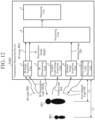
- FIG. 12 is a functional block diagram of a temperature measuring device TMD according to Embodiment 3.
- the temperature measuring device TMD according to Embodiment 3 is a combination of the temperature measuring device TMD (illustrated in FIG. 1 ) according to Embodiment 1 and the temperature measuring device TMD (illustrated in FIG. 9 ) according to Embodiment 2. More specifically, the temperature measuring device TMD according to Embodiment 3 includes an IR image acquiring unit 1, an IR illuminating unit 2, a processing unit 4, and a measuring unit 5 similar to the temperature measuring device TMD according to Embodiment 1 and the temperature measuring device TMD according to Embodiment 2.
- the temperature measuring device TMD according to Embodiment 3 includes a visible light image acquiring unit 3 similar to the temperature measuring device TMD according to Embodiment 1, and includes a distance image acquiring unit 6 and a near infrared light illuminating unit 7 similar to the temperature measuring device TMD according to Embodiment 2.
- the functions of the IR image acquiring unit 1, the IR illuminating unit 2, the visible light image acquiring unit 3, the processing unit 4, the measuring unit 5, the distance image acquiring unit 6, and the near infrared light illuminating unit 7 according to Embodiment 3 are the same as the functions of the IR image acquiring unit 1, the IR illuminating unit 2, the visible light image acquiring unit 3, the processing unit 4, the measuring unit 5, the distance image acquiring unit 6, and the near infrared light illuminating unit 7 according to Embodiments 1 and 2.
- the configuration of the temperature measuring device TMD according to Embodiment 3 is the same as the configuration (illustrated in FIG. 5 ) of the temperature measuring device TMD according to Embodiment 1.
- FIG. 13 is a flowchart illustrating an operation of the temperature measuring device TMD according to Embodiment 3. The operation of the temperature measuring device TMD according to Embodiment 3 will be described with reference to the flowchart in FIG. 13 below.
- Steps ST31 to ST36 Similar to steps ST11 to ST16 in Embodiment 1 and steps ST21 to ST26 in Embodiment 2, the processing unit 4 acquires distances L1 and L2 to persons JB1 and JB2, outer shapes GK1 and GK2, an image expansion range ZHH, and an image expansion amount ZHR, and corrects luminances of images GZ1 and GZ2 of the persons JB1 and JB2.
- Step ST37 Similar to step ST27 in Embodiment 2, the processing unit 4 calculates reflectivities R1 and R2 of the persons JB1 and JB1, that is, calculates emissivities ⁇ 1 and ⁇ 2 of the persons JB1 and JB2.
- Step ST38 Similar to step ST17 in Embodiment 1 and step ST28 in Embodiment 2, the measuring unit 5 measures the temperatures of the persons JB1 and JB2.
- the temperature measuring device TMD according to Embodiment 3 employs the configuration obtained by combining the temperature measuring device TMD according to Embodiment 1 and the temperature measuring device TMD according to Embodiment 2, and consequently can obtain the effect of the temperature measuring device TMD according to Embodiment 1 and the effect of the temperature measuring device TMD according to Embodiment 2.
- the temperature measuring device TMD uses a distance image DG obtained by the distance image acquiring unit 6 and consequently can improve robustness against environment where temperatures are measured in addition to the above effects even under, for example, environment in which a flare, a ghost, and the like appear in a visible camera included in the visible light image acquiring unit 3, and even under dim environment,.
- the temperature measuring device can be used to measure, for example, temperatures of persons.
- IR image acquiring unit 2: IR illuminating unit, 3: visible light image acquiring unit, 4: processing unit, 5: measuring unit, 6: distance image acquiring unit, 7: near infrared light illuminating unit, DG: distance image, GK1: outer shape, GK2: outer shape, GZ1: image, GZ2: image, HS: broken line portion, IRG: IR image, IRG: IR image, IRK: IR light, IRSG: IR illumination image, IRSK: IR illumination light, JB1: person, JB2: person, KB: storage medium, KG: visible light image, KK: visible light, L1: distance, L2: distance, MM: memory, NK: near infrared light, NY: input unit, P0: power, PC: processor, Pr: intensity, PR: program, R: reflectivity, R1: reflectivity, R2: reflectivity, SY: output unit, TMD: temperature measuring device, ZH: image expansion, ZHH: image
Landscapes
- Physics & Mathematics (AREA)
- General Physics & Mathematics (AREA)
- Spectroscopy & Molecular Physics (AREA)
- Health & Medical Sciences (AREA)
- Toxicology (AREA)
- Engineering & Computer Science (AREA)
- Multimedia (AREA)
- Signal Processing (AREA)
- Radiation Pyrometers (AREA)
Claims (6)
- Dispositif de mesure de température, comprenant :une unité d'éclairage d'infrarouge thermique (2) configurée pour irradier avec une lumière infrarouge thermique une cible dont la température doit être mesurée ;une unité d'acquisition d'image par éclairage infrarouge thermique (1) configurée pour acquérir, par l'intermédiaire d'une caméra infrarouge, une image d'éclairage infrarouge thermique incluant une image de la cible irradiée par la lumière infrarouge thermique ;une unité d'acquisition d'image infrarouge thermique (1) configurée pour acquérir, par l'intermédiaire de la caméra infrarouge, une image infrarouge thermique incluant l'image de la cible ;une unité d'acquisition d'image de lumière visible (3) configurée pour acquérir une image de lumière visible incluant l'image de la cible ;une unité de calcul (4) configurée pour calculer une plage d'expansion d'image de la cible sur la base de l'image de la cible dans l'image de lumière visible acquise et de l'image de la cible dans l'image d'éclairage IR acquise, en comparant l'image d'éclairage infrarouge thermique à l'image de lumière visible, l'expansion d'image se produisant dans les formes extérieures de l'image infrarouge thermique de la cible, et pour calculer une quantité d'expansion d'image en intégrant des luminances dans la plage d'expansion d'image de l'image infrarouge thermique ;une unité d'ajout (4) configurée pour ajouter la quantité d'expansion d'image calculée dans l'image infrarouge thermique acquise à la luminance de l'image infrarouge thermique de la cible ; etune unité de mesure (5) configurée pour mesurer une température de la cible sur la base de l'image infrarouge thermique de la cible à laquelle la quantité d'expansion d'image a été ajoutée.
- Dispositif de mesure de température, comprenant :une unité d'éclairage d'infrarouge thermique (2) configurée pour irradier avec une lumière infrarouge thermique une cible dont la température doit être mesurée ;une unité d'acquisition d'image par éclairage infrarouge thermique (1) configurée pour acquérir, par l'intermédiaire d'une caméra infrarouge, une image d'éclairage infrarouge thermique incluant une image de la cible irradiée par la lumière infrarouge thermique ;une unité d'acquisition d'image infrarouge thermique (1) configurée pour acquérir, par l'intermédiaire de la caméra infrarouge, une image infrarouge thermique incluant l'image de la cible ;une unité d'éclairage de mesure de distance (7) configurée pour irradier la cible avec une lumière d'éclairage de mesure de distance pour mesurer une distance ;une unité d'acquisition d'image de distance (6) configurée pour acquérir une image de distance incluant l'image de la cible irradiée avec la lumière d'éclairage de mesure de distance ;une unité de calcul (4) configurée pour calculer une plage d'expansion d'image de la cible sur la base de l'image de la cible dans l'image de distance acquise et de l'image de la cible dans l'image d'éclairage infrarouge thermique acquise, en comparant l'image d'éclairage infrarouge thermique à l'image de distance, l'expansion d'image se produisant dans les formes extérieures de l'image infrarouge thermique de la cible, et pour calculer une quantité d'expansion d'image en intégrant des luminances dans la plage d'expansion d'image de l'image infrarouge thermique ;une unité d'ajout (4) configurée pour ajouter la quantité d'expansion d'image calculée dans l'image infrarouge thermique acquise à la luminance de l'image infrarouge thermique de la cible ;une première unité d'acquisition (4) configurée pour acquérir une distance par rapport à la cible sur la base de l'image de distance acquise ;une seconde unité d'acquisition (4) configurée pour acquérir une émissivité de la cible sur la base de la distance acquise ; etune unité de mesure (5) configurée pour mesurer une température de la cible sur la base de l'image infrarouge thermique de la cible à laquelle la quantité d'expansion d'image a été ajoutée, et de l'émissivité acquise de la cible.
- Dispositif de mesure de température, comprenant :une unité d'éclairage d'infrarouge thermique (2) configurée pour irradier avec une lumière infrarouge thermique une cible dont la température doit être mesurée ;une unité d'acquisition d'image par éclairage infrarouge thermique (1) configurée pour acquérir, par l'intermédiaire d'une caméra infrarouge, une image d'éclairage infrarouge thermique incluant une image de la cible irradiée par la lumière infrarouge thermique ;une unité d'acquisition d'image infrarouge thermique (1) configurée pour acquérir, par l'intermédiaire de la caméra infrarouge, une image infrarouge thermique incluant l'image de la cible ;une unité d'acquisition d'image de lumière visible (3) configurée pour acquérir une image de lumière visible incluant l'image de la cible ;une unité d'éclairage de mesure de distance (7) configurée pour irradier la cible avec une lumière d'éclairage de mesure de distance pour mesurer une distance ;une unité d'acquisition d'image de distance (6) configurée pour acquérir une image de distance incluant l'image de la cible irradiée avec la lumière d'éclairage de mesure de distance ;une unité de calcul (4) configurée pour calculer une plage d'expansion d'image de la cible sur la base de l'image de la cible dans l'image de lumière visible acquise et de l'image de la cible dans l'image de distance acquise et de l'image de la cible dans l'image d'éclairage infrarouge thermique acquise, en comparant l'image d'éclairage infrarouge thermique à l'image de lumière visible, l'expansion d'image se produisant dans les formes extérieures de l'image infrarouge thermique de la cible, et pour calculer une quantité d'expansion d'image en intégrant des luminances dans la plage d'expansion d'image de l'image infrarouge thermique ;une unité d'ajout (4) configurée pour ajouter la quantité d'expansion d'image calculée dans l'image infrarouge thermique acquise à la luminance de l'image infrarouge thermique de la cible ; etune première unité d'acquisition (4) configurée pour acquérir une distance par rapport à la cible sur la base de l'image de distance acquise ;une seconde unité d'acquisition (4) configurée pour acquérir une émissivité de la cible sur la base de la distance acquise ; etune unité de mesure (5) configurée pour mesurer une température de la cible sur la base de l'image infrarouge thermique de la cible à laquelle la quantité d'expansion d'image a été ajoutée, et de l'émissivité acquise de la cible.
- Procédé de mesure de température, comprenant les étapes consistant à :par l'intermédiaire d'une unité d'éclairage infrarouge thermique (2), irradier avec une lumière infrarouge thermique une cible dont la température doit être mesurée ;par l'intermédiaire d'une unité d'acquisition d'image par éclairage infrarouge thermique (1), acquérir, par l'intermédiaire d'une caméra infrarouge, une image d'éclairage infrarouge thermique comprenant une image de la cible irradiée avec la lumière infrarouge thermique ;par l'intermédiaire d'une unité d'acquisition d'image infrarouge thermique (1), acquérir, par l'intermédiaire de la caméra infrarouge, une image infrarouge thermique comprenant l'image de la cible ;par l'intermédiaire d'une unité d'acquisition d'image de lumière visible (3), acquérir une image de lumière visible comprenant l'image de la cible ;par l'intermédiaire d'une unité de calcul (4), calculer une plage d'expansion d'image de l'image de la cible sur la base de l'image de la cible dans l'image de lumière visible acquise et de l'image de la cible dans l'image d'éclairage IR acquise en comparant l'image d'éclairage infrarouge thermique à l'image de lumière visible, l'expansion d'image se produisant dans les formes extérieures de l'image infrarouge thermique de la cible, et pour calculer une quantité d'expansion d'image en intégrant des luminances dans la plage d'expansion d'image de l'image infrarouge thermique ;par l'intermédiaire d'une unité d'ajout (4), ajouter la quantité d'expansion d'image calculée dans l'image infrarouge thermique acquise à la luminance de l'image infrarouge thermique de la cible ; etpar l'intermédiaire d'une unité de mesure (5), mesurer une température de la cible sur la base de l'image infrarouge thermique de la cible à laquelle la quantité d'expansion d'image a été ajoutée.
- Procédé de mesure de température, comprenant les étapes consistant à :par l'intermédiaire d'une unité d'éclairage infrarouge thermique (2), irradier avec une lumière infrarouge thermique une cible dont la température doit être mesurée ;par l'intermédiaire d'une unité d'acquisition d'image par éclairage infrarouge thermique (1), acquérir, par l'intermédiaire d'une caméra infrarouge, une image d'éclairage infrarouge thermique comprenant une image de la cible irradiée avec la lumière infrarouge thermique ;par l'intermédiaire d'une unité d'acquisition d'image infrarouge thermique (1), acquérir, par l'intermédiaire de la caméra infrarouge, une image infrarouge thermique comprenant l'image de la cible ;par l'intermédiaire d'une unité d'éclairage de mesure de distance, irradier la cible avec une lumière d'éclairage de mesure de distance pour mesurer une distance ;par l'intermédiaire d'une unité d'acquisition d'image de distance (6), acquérir une image de distance incluant l'image de la cible irradiée avec la lumière d'éclairage de mesure de distance ;par l'intermédiaire d'une unité de calcul (4), calculer une plage d'expansion d'image de l'image de la cible sur la base de l'image de la cible dans l'image de lumière visible acquise et de l'image de la cible dans l'image d'éclairage infrarouge acquise en comparant l'image d'éclairage infrarouge thermique à l'image de distance, l'expansion d'image se produisant dans les formes extérieures de l'image infrarouge thermique de la cible, et pour calculer une quantité d'expansion d'image en intégrant des luminances dans la plage d'expansion d'image de l'image infrarouge thermique ;par l'intermédiaire d'une unité d'ajout (4), ajouter la quantité d'expansion d'image calculée dans l'image infrarouge thermique acquise à la luminance de l'image infrarouge thermique de la cible ; etpar l'intermédiaire d'une première unité d'acquisition (4), acquérir une distance par rapport à la cible sur la base de l'image de distance acquise ;par l'intermédiaire d'une seconde unité d'acquisition (4), acquérir une émissivité de la cible sur la base de la distance acquise ; etpar l'intermédiaire d'une unité de mesure (5), mesurer une température de la cible d'infrarouge thermique sur la base de l'image infrarouge thermique de la cible à laquelle la quantité d'expansion d'image a été ajoutée, et de l'émissivité de la cible.
- Procédé de mesure de température, comprenant les étapes consistant à :par l'intermédiaire d'une unité d'éclairage infrarouge thermique (2), irradier avec une lumière infrarouge thermique une cible dont la température doit être mesurée ;par l'intermédiaire d'une unité d'acquisition d'image par éclairage infrarouge thermique (1), acquérir, par l'intermédiaire d'une caméra infrarouge, une image d'éclairage infrarouge thermique comprenant une image de la cible irradiée avec la lumière infrarouge thermique ;par l'intermédiaire d'une unité d'acquisition d'image infrarouge thermique (1), acquérir, par l'intermédiaire de la caméra infrarouge, une image infrarouge thermique comprenant l'image de la cible ;par l'intermédiaire d'une unité d'acquisition d'image de lumière visible (3), acquérir une image de lumière visible comprenant l'image de la cible ;par l'intermédiaire d'une unité d'éclairage de mesure de distance (7), irradier la cible avec une lumière d'éclairage de mesure de distance pour mesurer une distance ;par l'intermédiaire d'une unité d'acquisition d'image de distance (6), acquérir une image de distance incluant l'image de la cible irradiée avec la lumière d'éclairage de mesure de distance ;par l'intermédiaire d'une unité de calcul (4), calculer une plage d'expansion d'image de l'image de la cible sur la base d'une de l'image de la cible dans l'image de lumière visible acquise et de l'image de la cible dans l'image de distance acquise, et de l'image de la cible dans l'image d'éclairage infrarouge thermique acquise en comparant l'image d'éclairage infrarouge thermique à l'image de lumière visible ou l'image de distance, l'expansion d'image se produisant dans les formes extérieures de l'image infrarouge thermique de la cible, et pour calculer une quantité d'expansion d'image en intégrant des luminances dans la plage d'expansion d'image de l'image infrarouge thermique ;par l'intermédiaire d'une unité d'ajout (4), ajouter la quantité d'expansion d'image calculée dans l'image infrarouge thermique acquise à la luminance de l'image infrarouge thermique de la cible ; etpar l'intermédiaire d'une première unité d'acquisition (4), acquérir une distance par rapport à la cible sur la base de l'image de distance acquise ;par l'intermédiaire d'une seconde unité d'acquisition (4), acquérir une émissivité de la cible sur la base de la distance acquise ; etpar l'intermédiaire d'une unité de mesure (5), mesurer une température de la cible d'infrarouge thermique sur la base de l'image infrarouge thermique de la cible à laquelle la quantité d'expansion d'image a été ajoutée, et de l'émissivité de la cible.
Applications Claiming Priority (1)
| Application Number | Priority Date | Filing Date | Title |
|---|---|---|---|
| PCT/JP2021/021110 WO2022254642A1 (fr) | 2021-06-03 | 2021-06-03 | Dispositif de mesure de température et procédé de mesure de température |
Publications (3)
| Publication Number | Publication Date |
|---|---|
| EP4332526A1 EP4332526A1 (fr) | 2024-03-06 |
| EP4332526A4 EP4332526A4 (fr) | 2024-06-19 |
| EP4332526B1 true EP4332526B1 (fr) | 2025-06-25 |
Family
ID=84324014
Family Applications (1)
| Application Number | Title | Priority Date | Filing Date |
|---|---|---|---|
| EP21944144.1A Active EP4332526B1 (fr) | 2021-06-03 | 2021-06-03 | Dispositif de mesure de température et procédé de mesure de température |
Country Status (5)
| Country | Link |
|---|---|
| US (1) | US20230417600A1 (fr) |
| EP (1) | EP4332526B1 (fr) |
| JP (1) | JP7546775B2 (fr) |
| CN (1) | CN117355731A (fr) |
| WO (1) | WO2022254642A1 (fr) |
Family Cites Families (37)
| Publication number | Priority date | Publication date | Assignee | Title |
|---|---|---|---|---|
| JPH09218100A (ja) * | 1996-02-09 | 1997-08-19 | Mitsubishi Heavy Ind Ltd | 温度分布の表示装置 |
| US6107618A (en) * | 1997-07-14 | 2000-08-22 | California Institute Of Technology | Integrated infrared and visible image sensors |
| JP3565549B2 (ja) * | 1998-09-24 | 2004-09-15 | 東海カーボン株式会社 | 溶接管の溶接部温度測定方法および装置 |
| US7057256B2 (en) * | 2001-05-25 | 2006-06-06 | President & Fellows Of Harvard College | Silicon-based visible and near-infrared optoelectric devices |
| JP2005037366A (ja) * | 2003-06-24 | 2005-02-10 | Constec Engi Co | 赤外線構造物診断システム及び赤外線構造物診断方法 |
| KR100648308B1 (ko) * | 2004-08-12 | 2006-11-23 | 삼성전자주식회사 | 해상도 변환방법 및 장치 |
| WO2006060746A2 (fr) * | 2004-12-03 | 2006-06-08 | Infrared Solutions, Inc. | Camera a image combinee lumiere visible et infrarouge comportant un pointeur laser |
| KR101299074B1 (ko) * | 2006-03-03 | 2013-08-30 | 허니웰 인터내셔널 인코포레이티드 | 홍채 인코딩 시스템 |
| US7629582B2 (en) * | 2006-10-24 | 2009-12-08 | Raytheon Company | Dual band imager with visible or SWIR detectors combined with uncooled LWIR detectors |
| US7813889B2 (en) * | 2008-01-16 | 2010-10-12 | Welch Allyn, Inc. | Guiding IR temperature measuring device with probe cover |
| CN103542935B (zh) * | 2008-03-19 | 2016-02-03 | 超级医药成像有限公司 | 用于实时的组织氧合测量的小型化多光谱成像器 |
| US20090273675A1 (en) * | 2008-05-05 | 2009-11-05 | Flir Systems Ab | Ir camera and method for use with ir camera |
| US7915652B2 (en) * | 2008-10-24 | 2011-03-29 | Sharp Laboratories Of America, Inc. | Integrated infrared and color CMOS imager sensor |
| US8520970B2 (en) * | 2010-04-23 | 2013-08-27 | Flir Systems Ab | Infrared resolution and contrast enhancement with fusion |
| WO2012095322A1 (fr) | 2011-01-14 | 2012-07-19 | Sony Corporation | Système de réalisation d'image utilisant une unité d'objectif présentant des aberrations chromatiques longitudinales et procédé de fonctionnement |
| EP2530442A1 (fr) * | 2011-05-30 | 2012-12-05 | Axis AB | Procédés et appareil pour mesures thermographiques |
| JP5861190B2 (ja) | 2012-12-12 | 2016-02-16 | トヨタ自動車株式会社 | 非接触温度計測方法、及び、非接触温度計測装置 |
| DE112014000731T5 (de) | 2013-02-08 | 2015-10-22 | Denso Corporation | Bildverarbeitungsvorrichtung |
| US20140267757A1 (en) * | 2013-03-15 | 2014-09-18 | Fluke Corporation | Parallax correction in thermal imaging cameras |
| WO2016171090A1 (fr) | 2015-04-23 | 2016-10-27 | 富士フイルム株式会社 | Dispositif de traitement d'image, dispositif d'imagerie, procédé de traitement d'image et programme de traitement d'image |
| CN107836111B (zh) * | 2015-06-05 | 2020-08-11 | 菲力尔系统公司 | 用于增强动态范围红外成像的系统和方法 |
| US10152811B2 (en) * | 2015-08-27 | 2018-12-11 | Fluke Corporation | Edge enhancement for thermal-visible combined images and cameras |
| US10853926B2 (en) | 2016-03-29 | 2020-12-01 | Sony Corporation | Image processing device, imaging device, and image processing method |
| JP6620827B2 (ja) | 2017-04-14 | 2019-12-18 | Jfeスチール株式会社 | 放射温度測定装置及び放射温度測定方法 |
| GB2577646B (en) * | 2017-06-03 | 2022-09-14 | Teledyne FLIR LLC | Extensible architecture for surveillance and targeting imaging systems and methods |
| JP6939283B2 (ja) | 2017-09-05 | 2021-09-22 | ソニーグループ株式会社 | 画像処理装置、および画像処理方法、並びにプログラム |
| US10684370B2 (en) * | 2017-09-29 | 2020-06-16 | Veoneer Us, Inc. | Multifunction vehicle detection system |
| US20190141236A1 (en) * | 2017-11-06 | 2019-05-09 | Fluke Corporation | Inspection workflow using ojbect recognition and other techniques |
| US10850693B1 (en) * | 2018-04-05 | 2020-12-01 | Ambarella International Lp | Determining comfort settings in vehicles using computer vision |
| JP7129271B2 (ja) | 2018-08-16 | 2022-09-01 | セコム株式会社 | 画像処理装置 |
| WO2020160334A1 (fr) * | 2019-01-30 | 2020-08-06 | Cobalt Industries Inc. | Expérience de véhicule automatisée et réponse personnalisée |
| JP2020139866A (ja) * | 2019-02-28 | 2020-09-03 | 三星電子株式会社Samsung Electronics Co.,Ltd. | 温度計測装置、加熱調理器、および温度計測方法 |
| JP7259438B2 (ja) | 2019-03-19 | 2023-04-18 | コニカミノルタ株式会社 | 熱画像補正装置、熱画像補正方法、および、熱画像補正プログラム |
| US11336741B2 (en) * | 2019-11-01 | 2022-05-17 | Microsoft Technology Licensing, Llc | Image data segmentation and transmission |
| JP7404806B2 (ja) | 2019-11-22 | 2023-12-26 | 株式会社リコー | 撮像システム、結像光学系、及び画像処理方法 |
| US11816905B2 (en) * | 2020-03-19 | 2023-11-14 | Magna Electronics Inc. | Multi-camera vision system integrated into interior rearview mirror |
| CN111537083A (zh) * | 2020-06-22 | 2020-08-14 | 益逻触控系统公司 | 测量人的体温的方法和设备 |
-
2021
- 2021-06-03 WO PCT/JP2021/021110 patent/WO2022254642A1/fr not_active Ceased
- 2021-06-03 EP EP21944144.1A patent/EP4332526B1/fr active Active
- 2021-06-03 JP JP2023525269A patent/JP7546775B2/ja active Active
- 2021-06-03 CN CN202180098640.9A patent/CN117355731A/zh active Pending
-
2023
- 2023-09-13 US US18/367,554 patent/US20230417600A1/en active Pending
Also Published As
| Publication number | Publication date |
|---|---|
| EP4332526A4 (fr) | 2024-06-19 |
| WO2022254642A1 (fr) | 2022-12-08 |
| JP7546775B2 (ja) | 2024-09-06 |
| CN117355731A (zh) | 2024-01-05 |
| JPWO2022254642A1 (fr) | 2022-12-08 |
| US20230417600A1 (en) | 2023-12-28 |
| EP4332526A1 (fr) | 2024-03-06 |
Similar Documents
| Publication | Publication Date | Title |
|---|---|---|
| Lough et al. | Correlation of SWIR imaging with LPBF 304L stainless steel part properties | |
| EP3392635B1 (fr) | Dispositif de traitement d'image pour détection de gaz, procédé de traitement d'image pour détection de gaz, programme de traitement d'image pour détection de gaz, support d'enregistrement lisible par ordinateur comportant un programme de traitement d'image pour détection de gaz enregistré sur celui-ci, et système de détection de gaz | |
| US20100284570A1 (en) | System and method for gas leakage detection | |
| US7457721B2 (en) | Method and apparatus for measuring small displacement | |
| EP1678485B2 (fr) | Procede et camera infrarouge permettant de determiner le risque de condensation | |
| EA026014B1 (ru) | Способ предоставления данных изображения для конструирования изображения области целевого объекта при помощи итеративного процесса | |
| TW201237562A (en) | Method for measuring an optical system | |
| JP2021179404A (ja) | 温度測定システム | |
| KR20210024468A (ko) | 막두께 측정 장치 및 보정 방법 | |
| US7149652B2 (en) | Method for modeling detection of camouflaged targets | |
| EP3211456A1 (fr) | Dispositif de traitement de données, procédé de détermination de caractéristiques de pixels, procédé de traitement de données, et programme | |
| Deisenroth et al. | Measurement uncertainty of surface temperature distributions for laser powder bed fusion processes | |
| EP4332526B1 (fr) | Dispositif de mesure de température et procédé de mesure de température | |
| Lafargue-Tallet et al. | Active thermo-reflectometry for absolute temperature measurement by infrared thermography on specular materials | |
| Tan et al. | Surface reflectance retrieval from the intensity data of a terrestrial laser scanner | |
| JPH0663848B2 (ja) | 物体の表面温度測定方法 | |
| JP5279236B2 (ja) | 目標撮像探知装置 | |
| JP2007192579A (ja) | 温度計測装置及び温度計測方法 | |
| KR20210155223A (ko) | 열화상 카메라 | |
| Zheng et al. | 3D flame surface curvature analysis from reconstructed scanning across spherical expanding flames | |
| Sárosi et al. | Evaluation of reflectivity of metal parts by a thermo-camera | |
| Yu et al. | Construction and experimental verification of optimal expansion wavelength (OEW) inertia criterion based on three-channel wide-spectrum temperature measurement technology | |
| EP2113767A1 (fr) | Systèmes de tomographie informatisée et procédés correspondants impliquant une polarisation localisée | |
| US5872830A (en) | Device and method of imaging or measuring of a radiation source | |
| CN114325728B (zh) | 一种摄像头探测方法及装置 |
Legal Events
| Date | Code | Title | Description |
|---|---|---|---|
| STAA | Information on the status of an ep patent application or granted ep patent |
Free format text: STATUS: THE INTERNATIONAL PUBLICATION HAS BEEN MADE |
|
| PUAI | Public reference made under article 153(3) epc to a published international application that has entered the european phase |
Free format text: ORIGINAL CODE: 0009012 |
|
| STAA | Information on the status of an ep patent application or granted ep patent |
Free format text: STATUS: REQUEST FOR EXAMINATION WAS MADE |
|
| 17P | Request for examination filed |
Effective date: 20231124 |
|
| AK | Designated contracting states |
Kind code of ref document: A1 Designated state(s): AL AT BE BG CH CY CZ DE DK EE ES FI FR GB GR HR HU IE IS IT LI LT LU LV MC MK MT NL NO PL PT RO RS SE SI SK SM TR |
|
| A4 | Supplementary search report drawn up and despatched |
Effective date: 20240522 |
|
| RIC1 | Information provided on ipc code assigned before grant |
Ipc: G01J 5/48 20220101AFI20240515BHEP |
|
| DAV | Request for validation of the european patent (deleted) | ||
| DAX | Request for extension of the european patent (deleted) | ||
| GRAP | Despatch of communication of intention to grant a patent |
Free format text: ORIGINAL CODE: EPIDOSNIGR1 |
|
| STAA | Information on the status of an ep patent application or granted ep patent |
Free format text: STATUS: GRANT OF PATENT IS INTENDED |
|
| INTG | Intention to grant announced |
Effective date: 20250212 |
|
| GRAS | Grant fee paid |
Free format text: ORIGINAL CODE: EPIDOSNIGR3 |
|
| GRAA | (expected) grant |
Free format text: ORIGINAL CODE: 0009210 |
|
| STAA | Information on the status of an ep patent application or granted ep patent |
Free format text: STATUS: THE PATENT HAS BEEN GRANTED |
|
| AK | Designated contracting states |
Kind code of ref document: B1 Designated state(s): AL AT BE BG CH CY CZ DE DK EE ES FI FR GB GR HR HU IE IS IT LI LT LU LV MC MK MT NL NO PL PT RO RS SE SI SK SM TR |
|
| REG | Reference to a national code |
Ref country code: GB Ref legal event code: FG4D |
|
| REG | Reference to a national code |
Ref country code: CH Ref legal event code: EP |
|
| REG | Reference to a national code |
Ref country code: CH Ref legal event code: EP |
|
| REG | Reference to a national code |
Ref country code: IE Ref legal event code: FG4D |
|
| REG | Reference to a national code |
Ref country code: DE Ref legal event code: R096 Ref document number: 602021033121 Country of ref document: DE |
|
| PG25 | Lapsed in a contracting state [announced via postgrant information from national office to epo] |
Ref country code: FI Free format text: LAPSE BECAUSE OF FAILURE TO SUBMIT A TRANSLATION OF THE DESCRIPTION OR TO PAY THE FEE WITHIN THE PRESCRIBED TIME-LIMIT Effective date: 20250625 |
|
| REG | Reference to a national code |
Ref country code: LT Ref legal event code: MG9D |
|
| PG25 | Lapsed in a contracting state [announced via postgrant information from national office to epo] |
Ref country code: NO Free format text: LAPSE BECAUSE OF FAILURE TO SUBMIT A TRANSLATION OF THE DESCRIPTION OR TO PAY THE FEE WITHIN THE PRESCRIBED TIME-LIMIT Effective date: 20250925 Ref country code: GR Free format text: LAPSE BECAUSE OF FAILURE TO SUBMIT A TRANSLATION OF THE DESCRIPTION OR TO PAY THE FEE WITHIN THE PRESCRIBED TIME-LIMIT Effective date: 20250926 |
|
| PG25 | Lapsed in a contracting state [announced via postgrant information from national office to epo] |
Ref country code: BG Free format text: LAPSE BECAUSE OF FAILURE TO SUBMIT A TRANSLATION OF THE DESCRIPTION OR TO PAY THE FEE WITHIN THE PRESCRIBED TIME-LIMIT Effective date: 20250625 |
|
| PG25 | Lapsed in a contracting state [announced via postgrant information from national office to epo] |
Ref country code: HR Free format text: LAPSE BECAUSE OF FAILURE TO SUBMIT A TRANSLATION OF THE DESCRIPTION OR TO PAY THE FEE WITHIN THE PRESCRIBED TIME-LIMIT Effective date: 20250625 |
|
| PG25 | Lapsed in a contracting state [announced via postgrant information from national office to epo] |
Ref country code: RS Free format text: LAPSE BECAUSE OF FAILURE TO SUBMIT A TRANSLATION OF THE DESCRIPTION OR TO PAY THE FEE WITHIN THE PRESCRIBED TIME-LIMIT Effective date: 20250925 |
|
| PG25 | Lapsed in a contracting state [announced via postgrant information from national office to epo] |
Ref country code: LV Free format text: LAPSE BECAUSE OF FAILURE TO SUBMIT A TRANSLATION OF THE DESCRIPTION OR TO PAY THE FEE WITHIN THE PRESCRIBED TIME-LIMIT Effective date: 20250625 |
|
| REG | Reference to a national code |
Ref country code: NL Ref legal event code: MP Effective date: 20250625 |
|
| PG25 | Lapsed in a contracting state [announced via postgrant information from national office to epo] |
Ref country code: NL Free format text: LAPSE BECAUSE OF FAILURE TO SUBMIT A TRANSLATION OF THE DESCRIPTION OR TO PAY THE FEE WITHIN THE PRESCRIBED TIME-LIMIT Effective date: 20250625 |
|
| PG25 | Lapsed in a contracting state [announced via postgrant information from national office to epo] |
Ref country code: PT Free format text: LAPSE BECAUSE OF FAILURE TO SUBMIT A TRANSLATION OF THE DESCRIPTION OR TO PAY THE FEE WITHIN THE PRESCRIBED TIME-LIMIT Effective date: 20251027 |
|
| REG | Reference to a national code |
Ref country code: AT Ref legal event code: MK05 Ref document number: 1806873 Country of ref document: AT Kind code of ref document: T Effective date: 20250625 |
|
| PG25 | Lapsed in a contracting state [announced via postgrant information from national office to epo] |
Ref country code: IS Free format text: LAPSE BECAUSE OF FAILURE TO SUBMIT A TRANSLATION OF THE DESCRIPTION OR TO PAY THE FEE WITHIN THE PRESCRIBED TIME-LIMIT Effective date: 20251025 |
|
| PG25 | Lapsed in a contracting state [announced via postgrant information from national office to epo] |
Ref country code: AT Free format text: LAPSE BECAUSE OF FAILURE TO SUBMIT A TRANSLATION OF THE DESCRIPTION OR TO PAY THE FEE WITHIN THE PRESCRIBED TIME-LIMIT Effective date: 20250625 Ref country code: SM Free format text: LAPSE BECAUSE OF FAILURE TO SUBMIT A TRANSLATION OF THE DESCRIPTION OR TO PAY THE FEE WITHIN THE PRESCRIBED TIME-LIMIT Effective date: 20250625 |
|
| PG25 | Lapsed in a contracting state [announced via postgrant information from national office to epo] |
Ref country code: CZ Free format text: LAPSE BECAUSE OF FAILURE TO SUBMIT A TRANSLATION OF THE DESCRIPTION OR TO PAY THE FEE WITHIN THE PRESCRIBED TIME-LIMIT Effective date: 20250625 |
|
| PG25 | Lapsed in a contracting state [announced via postgrant information from national office to epo] |
Ref country code: PL Free format text: LAPSE BECAUSE OF FAILURE TO SUBMIT A TRANSLATION OF THE DESCRIPTION OR TO PAY THE FEE WITHIN THE PRESCRIBED TIME-LIMIT Effective date: 20250625 |
|
| PG25 | Lapsed in a contracting state [announced via postgrant information from national office to epo] |
Ref country code: EE Free format text: LAPSE BECAUSE OF FAILURE TO SUBMIT A TRANSLATION OF THE DESCRIPTION OR TO PAY THE FEE WITHIN THE PRESCRIBED TIME-LIMIT Effective date: 20250625 |
|
| PG25 | Lapsed in a contracting state [announced via postgrant information from national office to epo] |
Ref country code: SK Free format text: LAPSE BECAUSE OF FAILURE TO SUBMIT A TRANSLATION OF THE DESCRIPTION OR TO PAY THE FEE WITHIN THE PRESCRIBED TIME-LIMIT Effective date: 20250625 |
|
| PG25 | Lapsed in a contracting state [announced via postgrant information from national office to epo] |
Ref country code: ES Free format text: LAPSE BECAUSE OF FAILURE TO SUBMIT A TRANSLATION OF THE DESCRIPTION OR TO PAY THE FEE WITHIN THE PRESCRIBED TIME-LIMIT Effective date: 20250625 |
|
| PG25 | Lapsed in a contracting state [announced via postgrant information from national office to epo] |
Ref country code: DK Free format text: LAPSE BECAUSE OF FAILURE TO SUBMIT A TRANSLATION OF THE DESCRIPTION OR TO PAY THE FEE WITHIN THE PRESCRIBED TIME-LIMIT Effective date: 20250625 |
|
| PG25 | Lapsed in a contracting state [announced via postgrant information from national office to epo] |
Ref country code: IT Free format text: LAPSE BECAUSE OF FAILURE TO SUBMIT A TRANSLATION OF THE DESCRIPTION OR TO PAY THE FEE WITHIN THE PRESCRIBED TIME-LIMIT Effective date: 20250625 |