EP4332652A1 - Aktive optische kabelanordnung und montageverfahren dafür - Google Patents
Aktive optische kabelanordnung und montageverfahren dafür Download PDFInfo
- Publication number
- EP4332652A1 EP4332652A1 EP21938702.4A EP21938702A EP4332652A1 EP 4332652 A1 EP4332652 A1 EP 4332652A1 EP 21938702 A EP21938702 A EP 21938702A EP 4332652 A1 EP4332652 A1 EP 4332652A1
- Authority
- EP
- European Patent Office
- Prior art keywords
- optical
- optical cable
- ring
- half ring
- port adapter
- Prior art date
- Legal status (The legal status is an assumption and is not a legal conclusion. Google has not performed a legal analysis and makes no representation as to the accuracy of the status listed.)
- Pending
Links
- 230000003287 optical effect Effects 0.000 claims abstract description 369
- 239000013307 optical fiber Substances 0.000 claims abstract description 143
- 238000000034 method Methods 0.000 claims abstract description 19
- 230000000903 blocking effect Effects 0.000 claims abstract description 13
- 210000000078 claw Anatomy 0.000 claims description 33
- 238000009434 installation Methods 0.000 claims description 13
- 238000010586 diagram Methods 0.000 description 18
- 230000008569 process Effects 0.000 description 6
- 230000008878 coupling Effects 0.000 description 4
- 238000010168 coupling process Methods 0.000 description 4
- 238000005859 coupling reaction Methods 0.000 description 4
- 238000005516 engineering process Methods 0.000 description 4
- 230000009471 action Effects 0.000 description 2
- 230000008901 benefit Effects 0.000 description 2
- 230000005540 biological transmission Effects 0.000 description 2
- 238000004891 communication Methods 0.000 description 2
- 230000000694 effects Effects 0.000 description 2
- 238000000605 extraction Methods 0.000 description 2
- 230000006872 improvement Effects 0.000 description 2
- 238000003780 insertion Methods 0.000 description 2
- 230000037431 insertion Effects 0.000 description 2
- 230000009286 beneficial effect Effects 0.000 description 1
- 238000006243 chemical reaction Methods 0.000 description 1
- 230000007547 defect Effects 0.000 description 1
- 239000002360 explosive Substances 0.000 description 1
- 238000011900 installation process Methods 0.000 description 1
- 239000000463 material Substances 0.000 description 1
- 230000004048 modification Effects 0.000 description 1
- 238000012986 modification Methods 0.000 description 1
- 230000008439 repair process Effects 0.000 description 1
- 230000004044 response Effects 0.000 description 1
- 230000003313 weakening effect Effects 0.000 description 1
Images




Classifications
-
- G—PHYSICS
- G02—OPTICS
- G02B—OPTICAL ELEMENTS, SYSTEMS OR APPARATUS
- G02B6/00—Light guides; Structural details of arrangements comprising light guides and other optical elements, e.g. couplings
- G02B6/24—Coupling light guides
- G02B6/36—Mechanical coupling means
- G02B6/38—Mechanical coupling means having fibre to fibre mating means
- G02B6/3807—Dismountable connectors, i.e. comprising plugs
- G02B6/3897—Connectors fixed to housings, casing, frames or circuit boards
-
- G—PHYSICS
- G02—OPTICS
- G02B—OPTICAL ELEMENTS, SYSTEMS OR APPARATUS
- G02B6/00—Light guides; Structural details of arrangements comprising light guides and other optical elements, e.g. couplings
- G02B6/24—Coupling light guides
- G02B6/42—Coupling light guides with opto-electronic elements
- G02B6/4201—Packages, e.g. shape, construction, internal or external details
- G02B6/4219—Mechanical fixtures for holding or positioning the elements relative to each other in the couplings; Alignment methods for the elements, e.g. measuring or observing methods especially used therefor
- G02B6/4236—Fixing or mounting methods of the aligned elements
-
- G—PHYSICS
- G02—OPTICS
- G02B—OPTICAL ELEMENTS, SYSTEMS OR APPARATUS
- G02B6/00—Light guides; Structural details of arrangements comprising light guides and other optical elements, e.g. couplings
- G02B6/24—Coupling light guides
- G02B6/42—Coupling light guides with opto-electronic elements
- G02B6/4292—Coupling light guides with opto-electronic elements the light guide being disconnectable from the opto-electronic element, e.g. mutually self aligning arrangements
-
- G—PHYSICS
- G02—OPTICS
- G02B—OPTICAL ELEMENTS, SYSTEMS OR APPARATUS
- G02B6/00—Light guides; Structural details of arrangements comprising light guides and other optical elements, e.g. couplings
- G02B6/24—Coupling light guides
- G02B6/36—Mechanical coupling means
- G02B6/38—Mechanical coupling means having fibre to fibre mating means
- G02B6/3807—Dismountable connectors, i.e. comprising plugs
- G02B6/381—Dismountable connectors, i.e. comprising plugs of the ferrule type, e.g. fibre ends embedded in ferrules, connecting a pair of fibres
- G02B6/3825—Dismountable connectors, i.e. comprising plugs of the ferrule type, e.g. fibre ends embedded in ferrules, connecting a pair of fibres with an intermediate part, e.g. adapter, receptacle, linking two plugs
-
- G—PHYSICS
- G02—OPTICS
- G02B—OPTICAL ELEMENTS, SYSTEMS OR APPARATUS
- G02B6/00—Light guides; Structural details of arrangements comprising light guides and other optical elements, e.g. couplings
- G02B6/24—Coupling light guides
- G02B6/36—Mechanical coupling means
- G02B6/38—Mechanical coupling means having fibre to fibre mating means
- G02B6/3807—Dismountable connectors, i.e. comprising plugs
- G02B6/389—Dismountable connectors, i.e. comprising plugs characterised by the method of fastening connecting plugs and sockets, e.g. screw- or nut-lock, snap-in, bayonet type
-
- G—PHYSICS
- G02—OPTICS
- G02B—OPTICAL ELEMENTS, SYSTEMS OR APPARATUS
- G02B6/00—Light guides; Structural details of arrangements comprising light guides and other optical elements, e.g. couplings
- G02B6/24—Coupling light guides
- G02B6/42—Coupling light guides with opto-electronic elements
- G02B6/4201—Packages, e.g. shape, construction, internal or external details
- G02B6/4246—Bidirectionally operating package structures
Definitions
- the disclosure relates to the field of optical communication technology, and more specifically, relates to an active optical cable assembly and assembling method thereof.
- Active optical cables are composed of multimode optical fibers, optical transceiver devices, control chips, and parallel optical modules.
- the optical transceivers at both ends of the active optical cable provide functions of photoelectric conversion and optical transmission to improve the transmission speed and distance of the cable without weakening compatibility with standard electrical interfaces. Therefore, they are increasingly widely used in the field of optical communication.
- the optical transceiver in active optical cables comprises components such as a shell, an optical fiber, and a circuit board.
- the optical fiber is located at an end of the optical cable and is connected to the optical components on the circuit board.
- Active optical cables of related technologies require the optical fiber and circuit board connected to the optical cable to be installed together in the shell during assembly of the optical transceiver. That is, the optical fiber needs to be fixed and installed inside the optical transceiver, and cannot be assembled with the optical transceiver in a pluggable manner. Due to that the optical cable is thick and long, the entire assembly process is very inconvenient and the optical fiber will be damaged in case of any carelessness, resulting in the entire optical cable to be scrapped.
- this disclosure provides an active optical cable assembly and its assembly method, aiming to achieve a pluggable connection between the optical fiber connector and the optical transceiver, thereby achieving the function of not connecting the optical cable during the assembly of the optical transceiver, and solving the problem of optical cable scrapping caused by inconvenient assembly of the optical transceiver.
- the present disclosure provides an active optical cable assembly, comprising an optical fiber connector, an optical port adapter, and an optical transceiver which are arranged in sequence, wherein the optical port adapter is fixedly installed at an end of the optical transceiver, and the optical fiber connector is in a pluggable connection with the optical port adapter;
- an inner side of the optical port adapter is provided with elastic claws, and an outer side of a front end of the plug connector is provided with corresponding buckle slots; when the front end of the plug connector is inserted into the optical port adapter, the elastic claw is coupled to the buckle slot, and a side wall of a front end of the movable kit is squeezed onto an outside of the elastic claw to prevent the elastic claw from stretching out and detaching from the buckle slot.
- the blocking member specifically adopts an optical cable clamp ring, and an outer side of the intermediate connection sleeve is provided with a recession groove; when the optical cable clamp ring is sleeved on the recession groove, the movable kit can be prevented from sliding backwards; when the optical cable clamp ring is removed and the movable kit is caused to slide backwards to the recession groove, the plug connector can be pulled out from the optical port adapter.
- the optical cable clamp ring is a closed ring structure, comprising a first half ring and a second half ring, which are assembled to form a first ring core, for accommodating the intermediate connection sleeve of the optical fiber connector, and are connected in a buckle manner; wherein the first half ring comprises a first crossbeam and a first and a second side arms which are located at each of two ends of the first crossbeam, respectively; the second half ring comprises a second crossbeam and a third and a fourth side arms which are located at each of two ends of the second crossbeam, respectively.
- an outer side of the first side arm is provided with a first protrusion and a first recess
- an outer side of the second side arm is provided with a second protrusion and a second recess
- the optical cable clamp ring is a closed ring structure, comprising a third half ring and a fourth half ring, which are assembled to form a second ring core for accommodating the intermediate connection sleeve of the optical fiber connector, and are connected in a pivot manner and a buckle manner; wherein the third half ring comprises a third crossbeam and a fifth and sixth side arms which are located at each of two ends of the third crossbeam respectively; the fourth half ring comprises a fourth crossbeam and a seventh and eighth side arms located at each of two ends of the fourth crossbeam, respectively.
- the fifth side arm is provided with a hinge hole, and an inner side of the hinge hole is provided with an opening; the seventh side arm is provided with a hinge shaft; wherein the hinge shaft is squeezed into the hinge hole from the opening, so that the hinge shaft is concentric with the hinge hole, and the hinge shaft is rotate freely in the hinge hole;
- the optical cable clamp ring is an open ring structure, comprising a fifth crossbeam and a ninth and tenth side arms which are located at each of two ends of the fifth crossbeam;
- the intermediate connection sleeve is rotatable around the tail sleeve, and when the intermediate connection sleeve rotates at a preset angle, a blocking member that is preventable the movable kit from sliding backwards is formed; when the intermediate connection sleeve is in its initial position, the movable kit is slidable backwards to pull out the plug connector from the optical port adapter.
- the present disclosure further provides an assembling method of an active optical cable assembly, which is used for assembling the active optical cable assembly described in the first aspect, the assembling method comprising:
- the above technical solution proposed in this disclosure has the following beneficial effects compared to existing technologies: in the active optical cable assembly provided in this disclosure, when the optical fiber connector is inserted into the optical port adapter, the movable kit can be used to achieve fastening between the plug connector and the optical port adapter, and then a blocking member can be installed between the tail sleeve and the movable kit, which can prevent the movable kit from sliding backwards, whereby the movable kit can always play its fastening role to prevent the connector from detaching from the optical adapter.
- a pluggable connection can be achieved between the optical fiber connector and the optical transceiver, thereby achieving the function of not connecting the optical cable during the assembly of the optical transceiver, and solving the problem of cable scrapping caused by inconvenient assembly of the optical transceiver.
- the terms “inside”, “outside”, “vertical”, “horizontal”, “up”, “down”, “top”, “bottom”, “left”, “right”, “front”, “back”, etc. indicate the orientations or position relationships based on the orientations or position relationships shown in the accompanying drawings.
- the purpose is to only facilitate the description of the embodiments of the present disclosure and not to require the embodiments of the present disclosure to be constructed and operated in a specific orientation. Therefore, it should not be understood as a limitation on the embodiments of the present disclosure.
- an embodiment of the present disclosure provides an active optical cable assembly, as shown in Figures 1 to 5 , mainly comprising a first optical cable clamp ring 100, and an optical fiber connector 200, an optical port adapter 300, and an optical transceiver 400 which are sequentially connected; wherein the optical port adapter 300 is fixedly installed at an end of the optical transceiver 400, and the optical fiber connector 200 is in a pluggable connection with the optical port adapter 300.
- the optical fiber connector 200 comprises a movable kit 203, and a tail sleeve 204, an intermediate connection sleeve 205, and a plug connector 206 that are sequentially connected from rear to front.
- a front end of the plug connector 206 is used for coupling with the optical port adapter 300, and a rear end thereof is connected to the intermediate connection sleeve 205;
- the movable kit 203 is sleeved on the outer side of the plug connector 206, for preventing the plug connector from detaching from the optical port adapter 300 after the plug connector 206 is inserted into the optical port adapter 300, thereby achieving fastening between the optical fiber connector 200 and the optical port adapter 300, and the movable kit 203 is slidable forward and backward along the plug connector 206.
- an outer side of the intermediate connection sleeve 205 is provided with a recession groove, and the recession groove is connected to the rear end of the plug connector 206.
- the first optical cable clamp ring 100 is sleeved on the recession groove to prevent the movable kit 203 from sliding backwards.
- the fastening effect of the movable kit 203 fails, and thus the plug connector 206 can be pulled out from the optical port adapter 300.
- an inner side of the optical port adapter 300 is provided with an elastic claw 301 that extends outward, and an outer side of the front end of the plug connector 206 is provided with a corresponding buckle slot 2061.
- An outer side of the plug connector 206 is also provided with a spring groove positioned in buckle slot 2061, and the spring groove is provided with a spring 2062 therein;
- an inner side of the movable kit 203 is provided with a protrusion 2031, and a front end of the spring 2062 is in contact with a rear end of the protrusion 2031.
- the intermediate connection sleeve 205 is also provided with a first guide pin 201 and a second guide pin 202 which are located at the rear end of the recession groove, as shown in Figure 3 , for limiting a position of the movable kit 203 when it slides backwards to the recession groove; that is, the movable kit 203 can slide backwards to where at most the first guide pin 201 and the second guide pin 202 are positioned.
- the elastic claw 301 on the inner side of the optical port adapter 300 is exactly coupled to the clamp slot 2061 on the outer side of the plug connector 206.
- the spring 2062 is in a natural state, and a side wall of the front end of the movable sleeve 203 is squeezed onto an outer side of the elastic claw 301, which can prevent the elastic claw 301 from stretching out and detaching from the slot 2061, thereby achieving fastening the optical fiber connector 200 and the optical port adapter 300.
- the first optical cable clamp ring 100 is installed on the recession groove between the movable kit 203 and the tail sleeve 204 on the optical fiber connector 200, which can effectively prevent the movable kit 203 from sliding backwards, so that the front end of the movable kit 203 is always surrounding the outer side of the elastic claw 301 of the plug connector 206.
- the elastic claw 301 is effectively prevented from stretching out and separating from the clamp groove 2061.
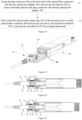
- the first optical cable clamp ring 100 needs to be removed from the recession groove, and then the movable kit 203 needs to be caused to slide backward; that is, an external force F as shown in Figure 5 is applied to the movable kit 203.
- the spring 2062 is compressed under the action of the protrusion 2031, and the movable kit 203 slides to the recession groove of the intermediate connection sleeve 205, such that the side wall of the front end of the movable kit 203 is gradually detached from the elastic claw 301, and at this time, the plug connector 206 of the optical fiber connector 200 can be pulled out from the optical port adapter 300.
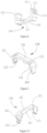
- the first optical cable clamp ring 100 is a closed ring structure, comprising a first half ring 110 and a second half ring 120.
- the first half ring 110 and the second half ring 120 are assembled to form a first ring core 101, for accommodating the intermediate connection sleeve 205 of the optical fiber connector 200.
- a first end of the first half ring 110 (i.e. the left end in the figure) and A first end of the second half ring 120 are connected through a buckle, and A second end of the first half ring 110 (i.e. the right end in the figure) and A second end of the second half ring 120 are connected through a buckle.
- the first half ring 110 comprises a first crossbeam 118 located in the middle, as well as a first side arm 111 and a second side arm 112 which are located at each of two ends of the first crossbeam 118, respectively.
- An inner side of the first crossbeam 118 is provided with a first recession groove 117, which is used to make way for the first guide pin 201 or the second guide pin 202 on the optical fiber connector 200.
- An outer side of the first side arm 111 is provided with a first protrusion 115 and a first recess 113, and an outer side of the second side arm 112 is provided with a second protrusion 116 and a second recess 114.
- the second half ring 120 comprises a second crossbeam 126 located in the middle, as well as a third side arm 121 and a fourth side arm 122 which are located at each of two ends of the second crossbeam 126, respectively.
- An inner side of the second crossbeam 126 is provided with a second recession groove 125 for making way for the first guide pin 201 or the second guide pin 202 on the optical fiber connector 200.
- the third side arm 121 is provided with a first clamp hook 123
- the fourth side arm 122 is provided with a second clamp hook 124.
- the first clamp hook 123 and the second clamp hook 124 on the second half ring 120 are squeezed into the first recess 113 and the second recess 114 in the first half ring 110, respectively, and are buckled with the first protrusion 115 and the second protrusion 116 on the first half ring 110, as shown in Figure 3 .
- the first half ring 110 and the second half ring 120 can be assembled through a buckle connection method and sleeved on the optical fiber connector 200.
- the movable kit can be used to achieve the fastening between the plug connector and the optical port adapter. Then, the first optical cable clamp ring can be sleeved on the recession groove of the optical fiber connector to prevent the movable kit from sliding backwards, and thus the movable kit can always play its fastening role to prevent the plug connector from detaching from the optical port adapter.
- a pluggable connection can be achieved between the optical fiber connector and the optical transceiver, achieving the function of not connecting the optical cable during the assembly of the optical transceiver, and solving the problem of cable scrapping caused by inconvenient assembly of the optical transceiver.
- an embodiment of the present disclosure also provides another active optical cable assembly, which differs from Embodiment 1 in that the structures of the optical cable clamp ring used are different.
- the active optical cable assembly mainly comprises a second optical cable clamp ring 500, as well as an optical fiber connector 200, an optical port adapter 300, and an optical transceiver 400 which are sequentially connected, wherein the optical port adapter 300 is fixedly installed at an end of the optical transceiver 400, and the optical fiber connector 200 is in a pluggable connection with the optical port adapter 300.
- optical fiber connector 200 and the optical port adapter 300 can be referred to the relevant introductions in Figure 4, Figure 5 , and Embodiment 1, and their contents will not be repeated here.
- the second optical cable clamp ring 500 is sleeved on the recession groove of the optical fiber connector 200, which can prevent the movable kit 203 from sliding backwards.
- the second optical cable clamp ring 500 is removed from the recession groove, and then the movable kit 203 is caused to slide backward to the recession groove to pull out the optical fiber connector 200 from the optical port adapter 300.
- the second optical cable clamp ring 500 is a closed ring structure, comprising a third half ring 510 and a fourth half ring 520.
- the third half ring 510 and the fourth half ring 520 are assembled to form a second ring core 501 for accommodating the intermediate connection sleeve 205 of the optical fiber connector 200.
- a first end of the third half ring 510 i.e. the left end in the figure
- a second end of the third half ring 510 i.e. the right end in the figure
- the third half ring 510 comprises a third crossbeam 518 located in the middle, as well as a fifth side arm 511 and a sixth side arm 512 which are located at each of two ends of the third crossbeam 518, respectively.
- the fourth half ring 520 comprises a fourth crossbeam 526 and a seventh side arm 521 and an eighth side arm 522 which are located at each of two ends of the fourth crossbeam 526, respectively.
- An inner side of the third crossbeam 518 is provided with a third recession groove 517 for making way for the first guide pin 201 or the second guide pin 202 on the optical fiber connector 200.
- An inner side of the fourth crossbeam 526 is provided with a fourth recession groove 525 for making way for the first guiding pin 201 or the second guiding pin 202 on the optical fiber connector 200.
- the fifth side arm 511 is provided with a hinge hole 513, whose inner side is provided with an opening 514, and the seventh side arm 521 is provided with a hinge shaft 523, wherein the hinge shaft 523 is squeezed into the hinge hole 513 from the opening 514, so that the hinge shaft 523 is concentric with the hinge hole 513, and the hinge shaft 523 can rotate freely in the hinge hole 513.
- An outer side of the sixth side arm 512 is provided with a third protrusion 515 and a third recess 516, and the eighth side arm 522 is provided with a third clamp hook 524.
- the hinge shaft 523 on the fourth half ring 520 rotates in the hinge hole 513 in the third half ring 510, and the third clamp hook 524 on the fourth half ring 520 squeezes into the third recess 516 in the third half ring 510 and snaps with the third protrusion 515 on the third half ring 510.
- the third half ring 510 and the fourth half ring 520 can be assembled in a pivot manner and buckle connection manner and sleeved on the optical fiber connector 200.
- the movable kit when the optical fiber connector is inserted into the optical port adapter, the movable kit can be used to achieve fastening, and then the second optical cable clamp ring can be sleeved on the recession groove of the optical fiber connector to prevent the movable kit from sliding backwards, whereby the movable kit can always play its fastening role to prevent the plug connector from detaching from the optical port adapter.
- a pluggable connection can be achieved between the optical fiber connector and the optical transceiver, thereby achieving the function of not connecting the optical cable during the assembly of the optical transceiver, and solving the problem of cable scrapping caused by inconvenient assembly of the optical transceiver.
- an embodiment of the present disclosure also provides another active optical cable assembly, which differs from Embodiments 1 and 2 in that the structures of the optical cable clamp ring used are different.
- the active optical cable assembly mainly comprises a third optical cable clamp ring 600, as well as an optical fiber connector 200, an optical port adapter 300, and an optical transceiver 400 that are sequentially connected, wherein the optical port adapter 300 is fixedly installed at an end of the optical transceiver 400, and the optical fiber connector 200 is in a pluggable connection with the optical port adapter 300.
- optical fiber connector 200 and the optical port adapter 300 can be referred to the relevant introductions in Figure 4, Figure 5 , and Embodiment 1, and their contents will not be repeated here.
- the third optical cable clamp ring 600 is sleeved on the recession groove of the optical fiber connector 200, which can prevent the movable kit 203 from sliding backwards.
- the third optical cable clamp ring 600 is removed from the recession groove, and then the movable kit 203 is forced to slide backwards to pull out the optical fiber connector 200 from the optical port adapter 300.
- the third optical cable clamp ring 600 is an open ring structure, comprising a fifth crossbeam 605 located in the middle and a ninth side arm 601 and a tenth side arm 602 which are located at each of two ends of the fifth crossbeam 605, respectively.
- An inner side of the fifth crossbeam 605 is provided with a fifth recession groove 606 for making way for the first guiding pin 201 or the second guiding pin 202 on the optical fiber connector 200.
- An end of the ninth side arm 601 is provided with a first clamp hook 603, and an end of the tenth side arm 602 is provided with a second clamp hook 604, wherein an installation port 607 is provided between the first clamp hook 603 and the second clamp hook 604.
- the middle of the optical cable clamp ring forms a third ring core 608, for accommodating the intermediate connection sleeve 205 of the optical fiber connector 200.
- the third optical cable clamp ring 600 When the third optical cable clamp ring 600 needs to be sleeved on the optical fiber connector 200, the third optical cable clamp ring 600 can be disconnected from the first clamp hook 603 and the second clamp hook 604, making the installation port 607 larger and thus the third optical cable clamp ring 600 is able to be installed at the recession groove of the optical fiber connector 200.
- the movable kit when the optical fiber connector is inserted into the optical port adapter, the movable kit can be used to achieve fastening, and then the third optical cable clamp ring can be sleeved on the recession groove of the optical fiber connector to prevent the movable kit from sliding backwards, whereby the movable kit can always play its fastening role to prevent the plug connector from detaching from the optical port adapter.
- a pluggable connection can be achieved between the optical fiber connector and the optical transceiver, thereby achieving the function of not connecting the optical cable during the assembly of the optical transceiver, and solving the problem of cable scrapping caused by inconvenient assembly of the optical transceiver.
- an embodiment of the present disclosure also provides another active optical cable assembly, which differs from Embodiments 1 to 3 in that the structures of the optical cable clamp ring used are different.
- the active optical cable assembly mainly comprises a fourth optical cable clamp ring 700, as well as an optical fiber connector 200, an optical port adapter 300, and an optical transceiver 400 that are sequentially connected, wherein the optical port adapter 300 is fixedly installed at an end of the optical transceiver 400, and the optical fiber connector 200 is in a pluggable connection with the optical port adapter 300.
- optical fiber connector 200 and the optical port adapter 300 can be referred to the relevant introductions in Figures 4, 5 , and Embodiment 1, and their contents will not be repeated here.
- the fourth optical cable clamp ring 700 is sleeved on the recession groove of the optical fiber connector 200, which can prevent the movable kit 203 from sliding backwards.
- the fourth optical cable clamp ring 700 is removed from the recession groove, and then the movable kit 203 is forced to slide backwards to pull out the optical fiber connector 200 from the optical port adapter 300.
- the fourth optical cable clamp ring 700 is a closed ring structure, comprising a sixth crossbeam 703 located in the middle, a seventh crossbeam 704 located on the opposite side of the sixth crossbeam 703, and a first elastic arm 701 and a second elastic arm 702 which are located at each of two ends of the sixth crossbeam 703, respectively.
- the sixth crossbeam 703, the first elastic arm 701, the seventh crossbeam 704, and the second elastic arm 702 form a fourth ring core.
- An inner side of the sixth crossbeam 703 is provided with a sixth recession groove 705 for making way for the first guiding pin 201 or the second guiding pin 202 on the optical fiber connector 200.
- An inner side of the seventh crossbeam 704 is provided with a seventh groove 706 for making way for the first guide pin 201 or the second guide pin 202 on the optical fiber connector 200.
- the first elastic arm 701 and the second elastic arm 702 are similar in shape to springs and can be compressed or stretched.
- the movable kit when the optical fiber connector is inserted into the optical port adapter, the movable kit can be used to achieve fastening, and then the fourth optical cable clamp ring can be sleeved on the recession groove of the optical fiber connector to prevent the movable kit from sliding backwards, whereby the movable kit can always play its fastening role to prevent the plug connector from detaching from the optical port adapter.
- a pluggable connection can be achieved between the optical fiber connector and the optical transceiver, thereby achieving the function of not connecting the optical cable during the assembly of the optical transceiver, and solving the problem of cable scrapping caused by inconvenient assembly of the optical transceiver.
- an embodiment of the present disclosure further provides a method for assembling an active optical cable assembly, to assemble the active optical cable assembly described in embodiments 1 to 4.
- the assembly method mainly comprises the following steps: Step 11, inserting the plug connector 206 at the front end of the optical fiber connector 200 into the optical port adapter 300, and using the movable kit 203 to achieve fastening between the plug connector 206 and the optical port adapter 300.
- the elastic claw 301 on the inner side of the optical port adapter 300 is coupled to the clamp slot 2061 on the outer side of the plug connector 206; at this time, the spring 2062 is in a natural state, and the side wall of the front end of the movable kit 203 is squeezed against the outer side of the elastic claw 301, which can prevent the elastic claw 301 from stretching out and detaching from the slot 2061, thereby achieving the fastening between the optical fiber connector 200 and the optical port adapter 300.
- the internal components of the optical transceiver 400 have been preassembled.
- Step 12 sleeving the first optical cable clamp ring 100 on the recession groove in the optical fiber connector 200 between the tail sleeve 204 and the movable kit 203, to prevent the movable kit 203 from sliding backwards.
- the optical cable clamp ring is installed on the recession groove in the optical fiber connector 200, which is located between the movable kit 203 and the tail sleeve 204.
- the active optical cable assembly is shown in Figures 1 , 12 , and 17 .
- the optical cable clamp ring is located in the recession groove behind the movable kit 203, which can effectively prevent the movable kit 203 from sliding backwards, as shown in Figure 4 , so that the front end of the movable kit 203 is always surrounding the outer side of the elastic claw 301 of the plug connector 206, thereby effectively preventing the elastic claw 301 from stretching out and detaching from the buckle slot 2061.
- the embodiments of this disclosure in the embodiments of this disclosure,
- the second half ring 120 is sleeved on the recession groove of the optical fiber connector 200 from the opposite side of the first half ring 110, so that the first clamp hook 123 and the second clamp hook 124 of the second half ring 120 are squeezed into the first recess 113 and the second recess 114 of the first half ring 110, respectively, and are buckled with the first protrusion 115 and the second protrusion 116 of the first half ring 110.
- the first optical cable clamp ring 100 can be sleeved on the recession groove.
- the specific disassembly steps are as follows: Firstly, removing the first optical cable clamp ring 100 from the recession groove of the optical fiber connector 200.
- the specific operations are as follows: using a tweezer and other tools to pry open the first clamp hook 123 and the second clamp hook 124 of the second half ring 120, so that the first clamp hook 123 and the second clamp hook 124 respectively detach from the first protrusion 115 and the second protrusion 116 of the first half ring 110; then sequentially removing the second half ring 120 and the first half ring 110 from the optical fiber connector 200.
- the specific operation is as follows: applying a force F opposite to the direction towards the optical transceiver 400 to the movable kit 203, so that the movable kit 203 slides to the recession groove of the intermediate connection sleeve 205, as shown in Figure 5 , whereby the side wall of the front end of the movable kit 203 gradually detaches from the elastic claw 301.
- the optical transceiver 400 can be easily opened and repaired without carrying an optical cable.
- the specific disassembly steps are as follows: Firstly, removing the second optical cable clamp ring 500 from the recession groove of the optical fiber connector 200.
- the specific operations are as follows: using a tweezer and other tools to pry open the third clamp hook 524 of the fourth half ring 520, detaching it from the third protrusion 515 of the third half ring 510, and then removing the second optical cable clamp ring 500 from the optical fiber connector 200.
- the installation steps of the third optical cable clamp ring 600 into the recession groove are as follows: Firstly, disconnecting the third optical cable clamp ring 600 from the first clamp hook 603 and the second clamp hook 604, making the installation port 607 larger.
- the installation port 607 becomes the initial size.
- the specific disassembly steps are as follows: Firstly, removing the third optical cable clamp ring 600 from the recession groove of the optical fiber connector 200.
- the specific operation is as follows: using a tool such as a finger or tweezer to simultaneously open the first clamp hook 603 and the second clamp hook 604, and increasing the installation port 607 until the third optical cable clamp ring 600 can be removed from the optical fiber connector 200.
- the installation steps of the fourth optical cable clamp ring 700 into the recession groove are as follows: Firstly, stretching outward the first elastic arm 701 and the second elastic arm 702 and causing the fourth ring core to become larger by applying an external force as shown in Figure 19 to the sixth crossbeam 703 and the seventh crossbeam 704.
- the specific disassembly steps are as follows: Firstly, stretching outward the first elastic arm 701 and the second elastic arm 702 by applying an external force as shown in Figure 19 to the sixth crossbeam 703 and the seventh crossbeam 704, to enable the fourth ring core to become larger until the fourth optical cable clamp ring 700 can be removed from the optical fiber connector 200 from the direction towards the tail sleeve 204.
- the optical fiber connector can conveniently insert and remove the optical port adapter installed on the optical transceiver, which can achieve a pluggable connection between the optical fiber connector and the optical transceiver, so that the assembly and disassembly of the optical transceiver do not require carrying optical cables, and the operation is convenient and efficient, which can solve the problem of optical cable scrapping caused by inconvenient assembly of the optical transceiver.
- an embodiment of the present disclosure provides an active optical cable assembly, and its difference from the aforementioned embodiment 4 is that the optical cable clamp ring is no longer set, but the backward sliding of the active kit is blocked by a rotatable intermediate connection sleeve.
- the optical fiber connector 200 comprises a movable kit 203, and a tail sleeve 204, an intermediate connection sleeve 205, and a plug connector 206, wherein the tail sleeve 204, the intermediate connection sleeve 205, and the plug connector 206 are sequentially connected from rear to front.
- a front end of the plug connector 206 is used for coupling with the optical port adapter 300, and a rear end is connected to the intermediate connection sleeve 205; the movable kit 203 is sleeved on an outer side of the plug connector 206 for preventing the plug connector from detaching from the optical port adapter 300 after the plug connector 206 is inserted into the optical port adapter 300, so that the fastening between the optical fiber connector 200 and the optical port adapter 300 is achieved, and the movable kit 203 can slide forward and backward along the plug connector 206.
- an outer side of the intermediate connection sleeve 205 is provided with a recession groove, which is connected to the rear end of the plug connector 206.
- the intermediate connection sleeve 205 can rotate around the tail sleeve 204, and when the intermediate connection sleeve 205 rotates at a preset angle around the axis, it can prevent the movable kit 203 from sliding backwards.
- the fastening effect fails when the movable kit 203 can slide backwards to the recession groove, and the plug connector 206 can be pulled out from the optical port adapter 300.
- an inner side of the optical port adapter 300 is provided with an elastic claw 301 that extends outward, and an outer side of the front end of the plug connector 206 is provided with a corresponding buckle slot 2061.
- the outer side of the plug connector 206 is further provided with a spring groove, which is located at the rear end of the card groove 2061, and the spring groove is provided with a spring 2062 therein;
- an inner side of the movable kit 203 is provided with a protrusion 2031, and a front end of the spring 2062 is in contact with a rear end of the protrusion 2031.
- the intermediate connection sleeve 205 is further provided with a first guide pin 201 and a second guide pin 202 which are located at the rear end of the recession groove, as shown in Figure 3 , for limiting the movable kit 203 when it slides backwards to the recession groove.
- the elastic claw 301 on the inner side of the optical port adapter 300 is just exactly coupled to the slot 2061 on the outer side of the plug connector 206.
- the spring 2062 is in a natural state, and the side wall of the front end of the movable sleeve 203 is squeezed on the outer side of the elastic claw 301, which can prevent the elastic claw 301 from stretching out and detaching from the slot 2061, thereby achieving the fastening between the optical fiber connector 200 and the optical port adapter 300.
- the intermediate connection sleeve 205 needs to be rotated back to its initial position, and then the movable kit 203 needs to be slid backwards.
- the spring 2062 is compressed under the action of the protrusion 2031, and the movable kit 203 slides to the recession groove of the intermediate connection sleeve 205, gradually detaching the side wall of the front end of the movable kit 203 from the elastic claw 301, and at this time, the plug connector 206 of the optical fiber connector 200 can be pulled out of the optical port adapter 300.
- the fitting relationship between the intermediate connection sleeve 205 and the movable kit 203 can be referred to Figure 24 .
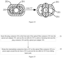
- the longitudinal dimension C at the recession groove is slightly smaller than the longitudinal dimension D inside the movable kit 203, so that when the movable kit 203 slides backwards, it can slide to the recession groove;
- the longitudinal dimension E at the recession groove is greater than the longitudinal dimension D inside the movable kit 203, so that the intermediate connection sleeve 205 can prevent the movable kit 203 from sliding backwards after rotating at a preset angle.
- the value range of the preset angle is (0°, 180°), preferably 90°; in Figure 25 , the intermediate connection sleeve 205 in the left figure is in the initial position, and the intermediate connection sleeve 205 rotates by 90° as shown in the right figure; at this time, the intermediate connection sleeve 205 can prevent the movable kit 203 from sliding backwards.
- the movable kit when the optical fiber connector is inserted into the optical port adapter, the movable kit can be used to fasten the plug connector and the optical port adapter, and then the intermediate connection sleeve can be rotated to prevent the movable kit from sliding backwards.
- the movable kit can always play its fastening role to prevent the plug connector from detaching from the optical port adapter.
- an embodiment of the present disclosure further provides a method for assembling an active optical cable assembly described in embodiment 6.
- the assembly method mainly comprises the following steps: Step 21, inserting the plug connector 206 at the front end of the optical fiber connector 200 into the optical port adapter 300, and using the movable kit 203 to achieve fastening between the plug connector 206 and the optical port adapter 300.
- Step 22 rotating the intermediate connection sleeve 205 on the optical fiber connector 200 at a preset angle around the tail sleeve 204 to prevent the movable kit 203 from sliding backwards.
- the intermediate connection sleeve 205 is rotated at a preset angle around the tail sleeve 204 from the initial position, such as 90°, as shown in Figure 24 .
- the intermediate connection sleeve 205 can effectively prevent the movable kit 203 from sliding backward, so that the front end of the movable kit 203 is always surrounding the elastic claw 301 of the plug connector 206, effectively preventing the elastic claw 301 from stretching out and separating from the slot 2061.
- the specific disassembly steps thereof are as follows: Firstly, rotating the intermediate connection sleeve 205 on the optical fiber connector 200 around the tail sleeve 204 at a preset angle and returning it to the initial position. For example, when the rotation angle is 90°, it is necessary to rotate the intermediate connection sleeve 205 from the right position in Figure 24 back to the left position in Figure 24 .
- the optical fiber connector can be conveniently inserted into or removed from the optical port adapter installed on the optical transceiver; that is a pluggable connection between the optical fiber connector and the optical transceiver can be achieved, so that the assembly and disassembly of the optical transceiver do not require optical cables, and the operation is convenient and efficient, which can solve the problem of optical cable scrapping caused by inconvenient assembly of the optical transceiver.
Landscapes
- Physics & Mathematics (AREA)
- General Physics & Mathematics (AREA)
- Optics & Photonics (AREA)
- Mechanical Coupling Of Light Guides (AREA)
- Optical Couplings Of Light Guides (AREA)
Applications Claiming Priority (2)
| Application Number | Priority Date | Filing Date | Title |
|---|---|---|---|
| CN202110471590.6A CN113189720B (zh) | 2021-04-29 | 2021-04-29 | 一种有源光缆组件及其组装方法 |
| PCT/CN2021/098889 WO2022227233A1 (zh) | 2021-04-29 | 2021-06-08 | 一种有源光缆组件及其组装方法 |
Publications (2)
| Publication Number | Publication Date |
|---|---|
| EP4332652A1 true EP4332652A1 (de) | 2024-03-06 |
| EP4332652A4 EP4332652A4 (de) | 2025-03-12 |
Family
ID=76980370
Family Applications (1)
| Application Number | Title | Priority Date | Filing Date |
|---|---|---|---|
| EP21938702.4A Pending EP4332652A4 (de) | 2021-04-29 | 2021-06-08 | Aktive optische kabelanordnung und montageverfahren dafür |
Country Status (4)
| Country | Link |
|---|---|
| US (1) | US20240248268A1 (de) |
| EP (1) | EP4332652A4 (de) |
| CN (1) | CN113189720B (de) |
| WO (1) | WO2022227233A1 (de) |
Families Citing this family (1)
| Publication number | Priority date | Publication date | Assignee | Title |
|---|---|---|---|---|
| CN117031644A (zh) * | 2023-06-30 | 2023-11-10 | 山东大学 | 光模块 |
Family Cites Families (44)
| Publication number | Priority date | Publication date | Assignee | Title |
|---|---|---|---|---|
| FR2855590B1 (fr) * | 2003-05-27 | 2006-10-20 | Caillau Ets | Embout de connexion rapide |
| CN101238614B (zh) * | 2005-08-08 | 2011-04-06 | 赖希勒及迪-马沙里有限公司 | 插头的保险装置 |
| US8855458B2 (en) * | 2008-03-06 | 2014-10-07 | Molex Incorporated | Fiber optic connector removal clips |
| CN102147507B (zh) * | 2010-02-05 | 2013-07-17 | 泰科电子(上海)有限公司 | 用于光纤适配器接口的安全装置 |
| US8500339B2 (en) * | 2011-01-11 | 2013-08-06 | Avago Technologies General Ip (Singapore) Pte. Ltd. | Locking device and method for use with a multi-fiber push on (MPO) connector module to prevent the MPO connector module from being decoupled from a receptacle |
| US10215926B2 (en) * | 2011-12-14 | 2019-02-26 | Commscope Technologies Llc | Multi-fiber fiber optic connection system with flexible, insertable pins |
| JP5898510B2 (ja) * | 2012-02-03 | 2016-04-06 | 矢崎総業株式会社 | 光コネクタ |
| CN104849814A (zh) * | 2014-02-14 | 2015-08-19 | 鸿富锦精密工业(深圳)有限公司 | 光纤连接器 |
| CN204009145U (zh) * | 2014-07-04 | 2014-12-10 | 深圳日海通讯技术股份有限公司 | 光纤连接器 |
| US9658409B2 (en) * | 2015-03-03 | 2017-05-23 | Senko Advanced Components, Inc. | Optical fiber connector with changeable polarity |
| US9684139B2 (en) * | 2015-05-29 | 2017-06-20 | Senko Advanced Components, Inc. | Optical fiber connector with changeable gender |
| US11175466B2 (en) * | 2015-07-02 | 2021-11-16 | Senko Advanced Components, Inc. | Bayonet lock MPO connector |
| US9995887B2 (en) * | 2016-01-04 | 2018-06-12 | Luxtera, Inc. | Method and system for a multi-fiber push-on/pull-off connector locking clip |
| US10989884B2 (en) * | 2017-04-07 | 2021-04-27 | Senko Advanced Components, Inc. | Behind the wall optical connector with reduced components |
| US10401576B2 (en) * | 2017-05-10 | 2019-09-03 | Senko Advanced Components, Inc. | MPO micro-latch-lock connector |
| US10620384B2 (en) * | 2017-05-25 | 2020-04-14 | Senko Advanced Components, Inc. | Adjustable polarity fiber optic connector assemblies with push-pull tabs |
| TWM550413U (zh) * | 2017-06-16 | 2017-10-11 | 建毅科技股份有限公司 | 光纖連接裝置 |
| CN207352215U (zh) * | 2017-10-26 | 2018-05-11 | 清远市亿源通光电科技有限公司 | 一种光纤连接器 |
| US11002923B2 (en) * | 2017-11-21 | 2021-05-11 | Senko Advanced Components, Inc. | Fiber optic connector with cable boot release having a two-piece clip assembly |
| JP6543326B1 (ja) * | 2017-12-25 | 2019-07-10 | 株式会社フジクラ | 光コネクタ |
| TWM561952U (zh) * | 2018-01-24 | 2018-06-11 | 建毅科技股份有限公司 | 光纖連接裝置 |
| JP7084195B2 (ja) * | 2018-04-16 | 2022-06-14 | 三和電気工業株式会社 | Mpoプラグ用ミニアダプタ |
| US10795094B2 (en) * | 2018-05-15 | 2020-10-06 | Senko Advanced Components, Inc. | Optical fiber connector |
| CN208270800U (zh) * | 2018-06-22 | 2018-12-21 | 清远市亿源通光电科技有限公司 | 一种光纤适配器 |
| US11237342B2 (en) * | 2018-06-28 | 2022-02-01 | Senko Advanced Components, Inc. | Adjustable polarity fiber optic connector assembly with shortened rotatable boot assembly |
| JP6796622B2 (ja) * | 2018-07-19 | 2020-12-09 | 株式会社フジクラ | 光コネクタ |
| CN110596823B (zh) * | 2018-09-03 | 2020-12-04 | 华为技术有限公司 | 一种光纤连接头及光纤连接器 |
| US10983280B2 (en) * | 2018-10-11 | 2021-04-20 | Senko Advanced Components, Inc. | Fiber splicing using a two-piece ferrule to form a MPO connector |
| US11181696B2 (en) * | 2019-02-22 | 2021-11-23 | Senko Advanced Components, Inc. | Adapter assembly having a return spring with a push-pull tab |
| US11215769B2 (en) * | 2019-03-07 | 2022-01-04 | Mellanox Technologies, Ltd. | MPO locking |
| JP6792673B1 (ja) * | 2019-06-25 | 2020-11-25 | 日本航空電子工業株式会社 | プラグコネクタ |
| CN114730049B (zh) * | 2019-09-17 | 2023-05-12 | 美国康涅克有限公司 | 卡套推 |
| US11726269B2 (en) * | 2019-09-24 | 2023-08-15 | Senko Advanced Components, Inc. | Lockable MPO connector for securing within a port of an adapter having a unique removal key |
| CN110501786B (zh) * | 2019-09-26 | 2024-09-03 | 广东亿源通科技股份有限公司 | 一种带锁扣的光纤连接器 |
| CN210376770U (zh) * | 2019-09-26 | 2020-04-21 | 清远市亿源通光电科技有限公司 | 一种带锁扣的光纤连接器 |
| US11105984B2 (en) * | 2019-10-11 | 2021-08-31 | Ii-Vi Delaware, Inc. | Retention device for optoelectronic connections |
| WO2021124702A1 (ja) * | 2019-12-18 | 2021-06-24 | 株式会社フジクラ | 固定部材、光コネクタ、牽引端付き光ケーブル及び光ケーブル敷設方法 |
| EP4082072A4 (de) * | 2019-12-27 | 2024-01-24 | K-Form, Inc. | Geteilter wellenleiterfilter |
| WO2021146560A1 (en) * | 2020-01-17 | 2021-07-22 | Commscope Technologies Llc | Gender changeable multi-fiber fiber optic connector |
| US12197013B2 (en) * | 2020-02-07 | 2025-01-14 | Fujikura Ltd. | Optical fiber pitch conversion jig, optical connector, pitch conversion cord, optical conversion box, and pitch conversion method for optical fibers |
| JP7434047B2 (ja) * | 2020-04-28 | 2024-02-20 | 日本航空電子工業株式会社 | 光コネクタ内蔵プラグの製造方法、及び光コネクタ内蔵プラグ |
| US11994722B2 (en) * | 2020-11-30 | 2024-05-28 | Corning Research & Development Corporation | Fiber optic adapter assemblies including an adapter housing and a locking housing |
| US11543601B1 (en) * | 2021-07-22 | 2023-01-03 | Suncall Technologies (Sz) Co., Ltd | MPO connector with high-density release clip and connector release tool |
| EP4202514A1 (de) * | 2021-12-21 | 2023-06-28 | II-VI Delaware, Inc. | Halter für einen mehrfaser-push-on-verbinder |
-
2021
- 2021-04-29 CN CN202110471590.6A patent/CN113189720B/zh active Active
- 2021-06-08 EP EP21938702.4A patent/EP4332652A4/de active Pending
- 2021-06-08 WO PCT/CN2021/098889 patent/WO2022227233A1/zh not_active Ceased
- 2021-06-08 US US18/564,456 patent/US20240248268A1/en active Pending
Also Published As
| Publication number | Publication date |
|---|---|
| CN113189720B (zh) | 2022-08-30 |
| EP4332652A4 (de) | 2025-03-12 |
| US20240248268A1 (en) | 2024-07-25 |
| WO2022227233A1 (zh) | 2022-11-03 |
| CN113189720A (zh) | 2021-07-30 |
Similar Documents
| Publication | Publication Date | Title |
|---|---|---|
| CN103140785B (zh) | 可变形套管总成和光纤连接器 | |
| CN208125956U (zh) | 光纤连接器和光纤电缆组件 | |
| KR101391039B1 (ko) | 이동가능한 플러그를 갖는 커넥터 어셈블리 | |
| US10948660B2 (en) | Connecting piece and optical fiber connector | |
| US8727638B2 (en) | Fiber channel-inter changeable fiber optic connector | |
| CN111061017B (zh) | 一种连接器和光纤连接组件 | |
| CN113296193B (zh) | 光学连接器及其光学连接器模块 | |
| US11754789B2 (en) | Fiber optic connector with unitary housing and fiber optic connector assembly | |
| US11585994B2 (en) | Active optical cable assemblies | |
| US9915793B2 (en) | Removal tool for a fiber optic ferrule alignment sleeve | |
| CN110609357A (zh) | 一种利用尾套解锁的mpo光纤连接器 | |
| CN101494337A (zh) | 具有滑动部件的连接器组件 | |
| WO2016053851A1 (en) | Fiber optic connector and pin change method for the same | |
| EP4332652A1 (de) | Aktive optische kabelanordnung und montageverfahren dafür | |
| EP4134717A1 (de) | Vorgefertigter verbinder, koppler und vorgefertigte verbinderanordnung | |
| CN220626715U (zh) | 一种光纤连接头、光纤连接插头及光纤连接组件 | |
| CN109143485A (zh) | Sc低型面连接器 | |
| KR100978778B1 (ko) | 분리 방지용 콘넥터 | |
| CN113341506A (zh) | 光纤的连接器及连接装置 | |
| CN113419311B (zh) | 一种插头连接器、插头固定部及连接器组件 | |
| EP3956705A1 (de) | Faseroptische verbinder mit trichterförmigen muffen und verfahren zu deren installation | |
| CN204595263U (zh) | 光纤连接器 | |
| CN115728874A (zh) | 连接器转接组件、连接器及光纤连接组件 | |
| CN219737834U (zh) | 一种防护壳体、插芯组件及光纤插头组件 | |
| CN106932864A (zh) | 连接器 |
Legal Events
| Date | Code | Title | Description |
|---|---|---|---|
| STAA | Information on the status of an ep patent application or granted ep patent |
Free format text: STATUS: THE INTERNATIONAL PUBLICATION HAS BEEN MADE |
|
| PUAI | Public reference made under article 153(3) epc to a published international application that has entered the european phase |
Free format text: ORIGINAL CODE: 0009012 |
|
| STAA | Information on the status of an ep patent application or granted ep patent |
Free format text: STATUS: REQUEST FOR EXAMINATION WAS MADE |
|
| 17P | Request for examination filed |
Effective date: 20231129 |
|
| AK | Designated contracting states |
Kind code of ref document: A1 Designated state(s): AL AT BE BG CH CY CZ DE DK EE ES FI FR GB GR HR HU IE IS IT LI LT LU LV MC MK MT NL NO PL PT RO RS SE SI SK SM TR |
|
| DAV | Request for validation of the european patent (deleted) | ||
| DAX | Request for extension of the european patent (deleted) | ||
| REG | Reference to a national code |
Ref country code: DE Ref legal event code: R079 Free format text: PREVIOUS MAIN CLASS: G02B0006420000 Ipc: G02B0006380000 |
|
| A4 | Supplementary search report drawn up and despatched |
Effective date: 20250210 |
|
| RIC1 | Information provided on ipc code assigned before grant |
Ipc: G02B 6/42 20060101ALI20250204BHEP Ipc: G02B 6/38 20060101AFI20250204BHEP |