EP4332701A1 - Systèmes et procédés pour supporter un processus d'usinage - Google Patents
Systèmes et procédés pour supporter un processus d'usinage Download PDFInfo
- Publication number
- EP4332701A1 EP4332701A1 EP22192867.4A EP22192867A EP4332701A1 EP 4332701 A1 EP4332701 A1 EP 4332701A1 EP 22192867 A EP22192867 A EP 22192867A EP 4332701 A1 EP4332701 A1 EP 4332701A1
- Authority
- EP
- European Patent Office
- Prior art keywords
- tool
- axis
- tool path
- machine
- limit value
- Prior art date
- Legal status (The legal status is an assumption and is not a legal conclusion. Google has not performed a legal analysis and makes no representation as to the accuracy of the status listed.)
- Withdrawn
Links
Images


Classifications
-
- G—PHYSICS
- G05—CONTROLLING; REGULATING
- G05B—CONTROL OR REGULATING SYSTEMS IN GENERAL; FUNCTIONAL ELEMENTS OF SUCH SYSTEMS; MONITORING OR TESTING ARRANGEMENTS FOR SUCH SYSTEMS OR ELEMENTS
- G05B19/00—Program-control systems
- G05B19/02—Program-control systems electric
- G05B19/18—Numerical control [NC], i.e. automatically operating machines, in particular machine tools, e.g. in a manufacturing environment, so as to execute positioning, movement or co-ordinated operations by means of program data in numerical form
- G05B19/406—Numerical control [NC], i.e. automatically operating machines, in particular machine tools, e.g. in a manufacturing environment, so as to execute positioning, movement or co-ordinated operations by means of program data in numerical form characterised by monitoring or safety
-
- G—PHYSICS
- G05—CONTROLLING; REGULATING
- G05B—CONTROL OR REGULATING SYSTEMS IN GENERAL; FUNCTIONAL ELEMENTS OF SUCH SYSTEMS; MONITORING OR TESTING ARRANGEMENTS FOR SUCH SYSTEMS OR ELEMENTS
- G05B2219/00—Program-control systems
- G05B2219/30—Nc systems
- G05B2219/35—Nc in input of data, input till input file format
- G05B2219/35336—Display locus and corresponding actual block
-
- G—PHYSICS
- G05—CONTROLLING; REGULATING
- G05B—CONTROL OR REGULATING SYSTEMS IN GENERAL; FUNCTIONAL ELEMENTS OF SUCH SYSTEMS; MONITORING OR TESTING ARRANGEMENTS FOR SUCH SYSTEMS OR ELEMENTS
- G05B2219/00—Program-control systems
- G05B2219/30—Nc systems
- G05B2219/35—Nc in input of data, input till input file format
- G05B2219/35473—Input limit values of speed, position, acceleration or force
-
- G—PHYSICS
- G05—CONTROLLING; REGULATING
- G05B—CONTROL OR REGULATING SYSTEMS IN GENERAL; FUNCTIONAL ELEMENTS OF SUCH SYSTEMS; MONITORING OR TESTING ARRANGEMENTS FOR SUCH SYSTEMS OR ELEMENTS
- G05B2219/00—Program-control systems
- G05B2219/30—Nc systems
- G05B2219/37—Measurements
- G05B2219/37093—Display speed
Definitions
- the present disclosure relates to a system for automated support of inspection and/or monitoring of a process performed by a machine tool, comprising a memory for storing machine-executable components and a processor operatively coupled to the memory and configured to execute the machine-executable components, wherein the machine-executable components include a tool path analysis component, the tool path analysis component being configured to process data, the process data being representative of a process consisting of at least one axis for moving a tool and a controller for controlling the at least one axis having machine tool is carried out, for example, to machine or manufacture a workpiece, to generate signals for visualizing a path of the tool - a tool path -, and to determine at least one variable which characterizes an axis movement of the at least one axis.
- the machine-executable components include a tool path analysis component, the tool path analysis component being configured to process data, the process data being representative of a process consisting of at least one axis for moving a tool and a controller for controlling the at
- a computer-aided method for the automated support of an inspection and/or monitoring of a process carried out by means of a machine tool wherein process data obtained from the machine tool, in particular during operation, for example in real time, the process data being representative of a process which is carried out by a at least one axis for moving a tool and a control device for controlling the machine tool having at least one axis is executed in order to machine a workpiece, signals for visualizing a path of the tool - a tool path - are generated, and at least one size, for example by deriving, is determined, which characterizes an axis movement of the at least one axis.
- control device In addition, a control device, a machine tool and a computer program are disclosed.
- a process-optimal feed rate is required.
- the feed of the tool is an important criterion in machining production in sub-processes such as finishing in order to be able to produce workpieces with high surface quality.
- Examples include 5-axis machines and machines with a non-Cartesian axis structure (e.g. hexapods). Two typical variants are known for defining the traversing movements.
- the user can program the spatial contour using either a circle or a straight line or a polynomial shape, so that the TCP (tool center point) is guided along the path according to the programmed contour.
- the user can program the target point in space/workpiece coordinates (WCS), which are mapped in machine coordinates (MCS machine coordinate system).
- WCS space/workpiece coordinates
- MCS machine coordinate system machine coordinates
- the TCP moves according to the maximum possible speeds in the axes on a curve that is not easily predictable (PTP for point-to-point). Due to the elimination of the movement of the TCP along a spatial curve, the PTP movement is faster than the TCP path movement. PTP movement is faster because it is direct (the PTP path is the shortest).
- the machine axes involved move directly from a selected coordinate transformation to the WCS target position without taking any constraints into account.
- Methods are known from the prior art in which the speed, acceleration or jerk of the movement of the TCP can be made visible using the process data recorded, for example, during a milling process or an additive manufacturing process.
- the TCP path can be colored with the feed rate, for example.
- the speed can be determined from process data and marked accordingly along the tool path, for example by coloring the tool path according to the determined speed.
- the task on which the present disclosure is based is to provide systems and methods that make it easier to identify drops in speed in manufacturing processes and to draw conclusions about their cause.
- the tool path analysis component is configured to check whether the determined variable exceeds at least one limit value assigned to at least one variable, and if the limit value is exceeded, at least an additional signal for, preferably visual, to generate identification of at least one area of the tool path where the limit value is exceeded.
- “Immediate readability” can be achieved, for example, by displaying the position in color, for example as a colored dot, and visualizing the extent of the deviation according to a color scale.
- the measures can include one or more measures from the group: NC part program change, changing the clamping situation in the machine's work area, changing tool lengths and, if necessary, tool orientations.
- the process data contains, for example, sensors attached or arranged on and/or in the machine tool recorded measured values and/or data derived from the measured values.
- the process can be, for example, a subtractive or additive machining process or manufacturing process.
- the tool can therefore be a cutting tool or cutting tool for drilling, milling, turning, grinding, honing, etc. or a laser or a nozzle.
- the process is a measuring process in which, for example, a workpiece is measured or measured.
- the tool can therefore be a measuring tool, for example a sensor device, in particular a sensor, for example a laser scanner, ultrasonic sensor or parabolic mirror, which can be fastened in a tool holder of an arm of the machine tool.
- it can be a measuring process using ultrasonic sensors.
- the surface of a workpiece can be examined, for example for its porosity.
- the sound can be delivered to a workpiece surface (e.g. from several sides) using water jets.
- the reaction of the workpiece can then be measured with one or more ultrasonic sensors, whereby the ultrasonic sensors can be positioned in tool holders and thus represent a “measuring tool”.
- a machine tool can also be a robot or a robot arm, since a robot - from a control perspective - can be viewed as a machine tool with robot kinematics.
- the robots have - mainly - rotary axes.
- the tool path analysis component is configured to: Visualize signals and the additional signal on a display device.
- control device has a parameterization, wherein the parameterization includes the at least one limit value.
- the limit value can be, for example, a dynamic limit of the axis, for example the feed axis of the machine tool.
- a possible cause of speed drops are the dynamic limits of the feed axes of the machine tool.
- Each machine axis has a speed, acceleration and jerk limit set by the machine manufacturer.
- a jerk limit related to the tool path can be provided.
- the dynamic limits are part of the parameterization of the CNC (NC control). They limit the dynamics of the axes according to the design, electrical or control specifications/project planning of the distributor/machine manufacturer.
- the dynamic limits can, among other things, ensure that the corresponding axes do not experience forces that can, for example, lead to their constructive irreversible changes.
- the process data includes data representative of the position of the at least one axis and/or the tool, in particular position data of the axis, which are preferably representative of the tool position.
- the tool path analysis component can then determine the actual speeds, accelerations and displacements over time, for example by deriving the tool path (the tool path) or the positions of the machine axes over time. The tool path analysis component can then, for example, check whether one of the dynamic limits has been exceeded at the respective coordinates.
- the tool path analysis component indicates, for example via color coding and additional information, where in the point cloud that forms the visualization of the tool path which dynamic limit has been exceeded.
- the process data has a reference to the part program that runs on the control device and in particular on an NC control (NC for numerical control).
- the process data contains references to certain G functions (which can correspond, for example, to certain dynamic groups of the machine tool, e.g. finishing, roughing, positioning, etc.) and preferably to G code lines, so that the search for possible errors and causes is simplified.
- the process data can therefore have a reference to a part program for the machining process or to the part program of the machining process, the process data in particular containing a reference to G functions of the part program and preferably to G code lines of the part program
- the process data can include the following information.
- the process data can include axis position of each axis of a multi-axis (3, 4, 5, 6, ...) machine tool.
- the process data can include tool positions in the spatial or workpiece coordinate system.
- the process data can contain information about which G function, i.e. H. a specific function in the part program is currently active (if the process is carried out in real time) or was active.
- the process data can therefore contain a relationship between the axis positions, the tool positions and the specific G functions, so that specific G functions can be assigned to the axis positions and the tool positions.
- the tool path analysis component is configured to determine position data of the at least one axis, for example in a machine tool coordinate system, from the signals for visualizing the tool path, which are generated, for example, in a workpiece coordinate system. Through this The knowledge is gained as to which axis and how, in relation to the workpiece coordinate system, was involved.
- the at least one variable is a physical, time-dependent variable that preferably directly describes the axis movement.
- the at least one variable is speed, acceleration, jerk or shock. This can be a speed-related and/or position-related jerk.
- the limit values can be one or more of the following dynamic limits of the machine: maximum axis speed - MAX AX_SPEED, maximum axis acceleration - MAX_AX_BESCHL, maximum axis jerk - MAX_AX_RUCK, maximum tool tip jerk - MAX_BAHN_RUCK. These limits can be changed and adjusted in the part program.
- the dynamic limits are usually stored in the machine configuration (in channel or axis machine data) and can be made available to the tool path analysis component or retrieved from the tool path analysis component.
- the tool path is a trajectory (movement path or path) stored by the tool, in particular by the tool center point (e.g. from the tool tip or from the tool center (for ball mills)) or, if the process is simulated before it is actually carried out, to be stored. is.
- the visualization is a 2D or 3D visualization.
- the tool path analysis component is configured to obtain the process data during operation, i.e., during operation of the machine tool. This is therefore real-time data.
- the tool path analysis component is configured to generate the additional signal or a further additional signal when the at least one variable exceeds a threshold value that can be predetermined by an operator and is dependent on the at least one limit value.
- the threshold value can be set, for example, as a fraction of the limit value.
- such thresholds are user-defined warning limits.
- the additional signal or the further additional signal is thus generated when the value of the at least one variable comes too close to the limit value, for example the dynamic limit.
- the axis is a feed axis and the axis movement is a feed movement.
- the machine tool comprises two or more axes, with the tool path analysis component being configured to determine the at least one size for each axis and to check whether the at least one limit value is exceeded.
- two or more axes can be combined (in terms of software) to form a (machine tool) channel.
- the control of the machine tool or the robot can be programmed so that several axes are moved simultaneously in a common movement (as a unit). In this case we can speak of a channel movement.
- Limit values e.g. dynamic limits
- the parameterization of an NC control can include channel limit values.
- Usually a channel movement is slower than the movements of individual axes. Compliance with the limit values assigned to channel movement is therefore safer.
- the channel limit values set, for example, dynamic limits for the interaction of the axes on your path, path jerk, path speed, path acceleration.
- the tool path analysis component is set up to generate different additional signals for different axes, which preferably lead to different markings, for example in terms of design.
- the task is also solved with a control device with the system described above.
- control device has a part program (NC program, G-code file) that can be executed on the control device.
- control device can include an NC control or be designed as an NC control.
- control device can include a computing device (e.g. an industrial computer (industrial PC), for example in the form of an edge device, or laptop, etc.).
- industrial PC industrial computer
- the task is also achieved with a machine tool with at least one axis for moving a tool, for example for subtractive or additive manufacturing of a workpiece, and with an above-mentioned control device.
- the machine tool further comprises a display device assigned to the control device, on which the signals and the additional signal can be visualized, preferably simultaneously.
- the object is also achieved according to the invention with a method mentioned at the beginning by checking whether the determined variable exceeds at least one limit value assigned to at least one variable, and when the limit value is exceeded, at least an additional signal for, for example visual, identification of at least one area of the tool path at which the limit value is exceeded is generated.
- the task is solved with a computer program which includes commands which, when the program is executed by a computer, cause it to carry out the aforementioned method.
- the user therefore does not need any in-depth mechatronic knowledge in order to be able to attribute drops in path speed/points of limited productivity and quality to the fact that limit values have been reached.
- Such an analysis can be carried out with just a few mouse clicks. Leads the user the analysis with virtual data from the virtual NCK, which in this case is no less meaningful than with data from the real machine, then he already receives a statement as to whether the dynamic values can be maintained without having to produce a single missing part. Based on recorded target values, production can be fully validated in the virtual world.
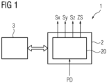
- FIG 1 shows a system 1, which corresponds to a system for automated support of an inspection and/or monitoring of a machining process.
- the system 1 includes a memory 2.
- Machine-executable or computer-executable components can be stored on the memory 2.
- a processor 3 which can be designed, for example, as an electronic circuit, is operatively coupled to the memory 2.
- the processor 3 is configured to execute the machine-executable components.
- the machine-executable components include a tool path analysis component 20.
- the tool path analysis component 20 can, for example, be designed as software, in particular as a software module.
- the tool path analysis component includes 20 commands or instructions that the processor 3 can process.
- the tool path analysis component 20 is configured to receive process data PD or to retrieve the process data PD, for example.
- the process data PD contains from and/or in the machine tool 100 (see FIG 4 ) attached or arranged sensors (not shown) recorded measured values and / or data derived from the measured values, for example KPIs (Key Performance Indicators), secondary measured variables, etc.
- KPIs Key Performance Indicators
- the process data PD is representative of a machining process which is carried out by at least one axis for moving a tool 101 and a control device for controlling the machine tool 100 having at least one axis in order to machine a workpiece 103 (see FIG 4 ).
- the axis is, for example, a feed axis. Preferably it is subtractive processing.
- the tool path analysis component 20 is configured to generate PD signals Sx, Sy, Sz for visualizing a path of the tool - a tool path WB1, WB2 - from the process data.
- FIG 2 and FIG 3 illustrate such a visualization.
- the tool path WB1 and WB2 can, for example, be visualized in a Cartesian coordinate system X, Y, Z.
- the tool path WB1, WB2 is visualized, which is a tool, for example a tool 101 FIG 4 during a subtractive machining process.
- Such a tool path WB1, WB2 also corresponds to the surface of the workpiece, for example the workpiece 103 FIG 4 , which occurs when machining with the tool.
- the signals Sx, Sy, Sz can, for example, describe the position of the tool in the X, Y, Z coordinate system.
- the tool path analysis component 20 is configured to determine variables that characterize an axis movement of the at least one axis.
- a further signal can be generated to correspondingly identify the size on or along the tool path WB1, WB2.
- the tool path WB1, WB2 can be colored according to the determined values of the at least one variable. This is in FIG 2 and FIG 3 illustrated in grayscale.
- the variable can, for example, be a physical, time-dependent variable that preferably directly describes the axis movement.
- the quantity is a speed, an acceleration, or a jerk of the corresponding axis.
- the size can be a corresponding component of the speed, acceleration, or jerk in the X, Y, Z coordinate system.
- tool path analysis component 20 is configured to check whether the determined size is at least one that exceeds at least one size assigned limit.
- the limit value can be, for example, a dynamic limit of the axes, for example the feed axis of the machine tool.
- Each machine axis has a speed, acceleration and jerk limit set, for example, by the machine manufacturer. Furthermore, a jerk limit related to the tool path (tool center point) WB1, WB2 can be provided. These values are also known as dynamic limits.
- the limit values in particular the dynamic limits, can be part of a parameterization of an NC control (NC for numerical control), for example the NC control 102 of the control device of the machine tool 100 FIG 4 .
- NC control for numerical control
- the limit values prevent the corresponding axis from moving faster than specified by the part program. If such a case occurs, the NC control reduces the corresponding size, e.g. the feed, in order not to exceed the limit values, especially the dynamic limits.
- This can, for example, lead to drops of at least one magnitude, for example to drops in speed, which can be noticeable in the surface quality of the workpiece.
- the tool path analysis component 20 is configured to generate at least one additional signal ZS when at least one of the limit values, preferably the dynamic limits, is reached or exceeded.
- the additional signal ZS serves to preferably visually identify that area or those areas BG of the tool path WB1 in which the limit value has been reached or exceeded.
- FIG 3 It can be seen that the tool path WB2 was traversed without reaching or exceeding the limit values have been.
- the tool path WB2 corresponds to a process in which, based on the information of the FIG 2 Corresponding corrections have been made in the machining process, preferably the corresponding controlled system has been optimized.
- the tool path analysis component 20 can be configured to display the signals Sx, Sy, Sz and the additional signal ZS on a display device, for example on a display device 104 of the machine tool 100 FIG 4 to visualize.
- the marking can be designed as an oval or rectangular border, for example.
- the marking preferably includes information about exactly which limit value has been reached or exceeded.
- the identification includes the information about the at least one size and/or the at least one axis. This information can, for example, be displayed in an additional window on the display device.
- the labeling can include information about what percentage of the limit value has been reached or by what percentage the limit value has been exceeded.
- FIG 5 is an enlarged section of one of the BG areas
- FIG 2 represents, illustrates.
- the marking of the areas BG means that a deviation of the at least one variable at a specific position on the tool path WB1, WB2 can be immediately determined and read.
- the information in the marking makes it possible, among other things, to determine the cause of the speed drops that led to the BG areas.
- the position can be displayed in color, for example as a colored dot, and/or the extent of deviation according to a color scale.
- the points can be designed differently.
- FIG 5 reveals three points GSW, which are shown as filled circles. All other points can be seen as empty circles.
- a filled circle can be represented as a red dot and an empty circle as a green dot.
- the reference symbol "GSW” and the arrows pointing to the points can also be visualized.
- the displayed “GSW” can contain an indication of which limit value or user-defined threshold value was reached or exceeded for which axis and/or channel.
- the process data PD includes data representative of the position of the at least one axis, in particular position data of the axis, which are preferably representative of the tool position.
- the at least one variable can be determined, for example, from position data by derivation (according to time).
- the tool path WB1, WB2 can be visualized as a 2D or 3D contour or line. More dimensions for visualization are also conceivable: 3D contour and coloring (of the point cloud) - 4D; 3D contour and coloring and line thickness - 5D; 3D and 3D vector (to show curvature direction, for example) - 6D.
- the tool path analysis component 20 can also be configured to generate the additional signal when the at least one variable exceeds a threshold value that is dependent on the at least one limit value, for example predetermined by an operator.
- the threshold value can be set, for example, as a fraction of the limit value.
- the marking can preferably indicate or contain information about the percentage by which the threshold value has been exceeded.
- FIG 4 shows a machine tool 100, for example a system 1 of FIG 1 can include.
- the machine tool 100 can have multiple axes, for example feed axes, for moving the tool 101 and a control device that includes an NC controller 102 for controlling the axes.
- the machine tool 100 is a 5- or 6-axis machine tool.
- the machine tool 100 usually processes a workpiece 103. This is preferably subtractive processing. It goes without saying that the system 1 can also be used in an additive manufacturing process.
- the system 1 can be implemented, for example, in the control device, in particular in the NC control 102.
- the control device can also include further units that are structurally separate from the NC control 102, for example.
- control device may include an edge device 105.
- the edge device 105 can, for example, be designed as an industrial computer and be set up to record the process data PD, cache it, pre-process it, make it available to a cloud platform (not shown here), etc.
- the system 1 can also be implemented in such an edge device 105 and, for example, the display device 104 Use the NC control 102 to visualize the signals Sx, Sy, Sz and the additional signal ZS.
- the control device can also include one or more other preferably mobile devices 106, for example smartphone, laptop, tablet, etc.
- the system 1 can be in each of these, for example via a local network with the edge device 105 and/or with the NC Controller 102 connected devices are implemented. Alternatively or additionally, the devices 106 may be connected to the cloud platform.
- the tool path analysis component 20 is configured to obtain the process data PD during operation, i.e., during operation of the machine tool 100. This means that process data PD is received in real time.
- the tool path analysis component 20 can be configured to determine the at least one quantity for each axis and to check whether the at least one limit value has been reached or exceeded.
- Different axes can be assigned different limit values for the at least one variable, whereby the tool path analysis component 20 can be configured to check for each axis whether the corresponding at least one limit value has been reached or exceeded.
- the tool path analysis component 20 can be set up to generate different additional signals for different axes, which preferably lead to different (eg in design) identification.
- each axis can be assigned a specific color of identification, and different colors can be used for different axes.
- the parameterization of the NC control 102 preferably has at least one limit value for the at least one variable for each axis.
- control device in particular NC control 102, includes a machine-executable program code, for example a part program or G-code file.
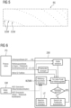
- FIG 6 shows a flowchart showing a computer-aided method for automatically supporting an inspection and/or monitoring of a subtractive machining process, which is carried out when a tool path analysis component runs on a computing device, for example the tool path analysis component 20 on the control device.
- the tool path analysis component 200 receives process data PD that is representative of the machining process during operation of the machine tool.
- the process data PD can include, for example, the following information.
- the machine tool is, for example, a five-axis machine tool, so that the process data PD includes axis position A1, ..., A5 ("Axis position [A1, ..., A5]" in FIG 6 ).
- the process data PD includes tool positions in the spatial or workpiece coordinate system u1, u2, u3.
- the process data PD can contain information about which G function, ie a specific function in the part program that is executed on the control device, in particular on the NC control, is currently active ("Active G function" in FIG 6 ). In this way it is possible to create a relationship between the G-code lines and the process data PD.
- a specific G function can be assigned to the axis positions A1, ..., A5 and the tool positions u1, u2, u3.
- the process data PD can be sent to the tool path analysis component 200 in the form of corresponding signals (see FIG 6 ) to provide.
- the tool path analysis component 200 receives limit values GW assigned to the corresponding axes and the corresponding quantities.
- the GW limits include limit values in machine coordinates - the "MCS limits" MAX_AX_SCHW[0..5] ⁇ 1..5>; MAX_AX_BESCHL[0..5] ⁇ 1..5>; MAX_AX_RUCK[0..5] ⁇ 1..5> - and the limit values in spatial/workpiece coordinates - the "WCS limit values" MAX_BAHN_RUCK[0..5].
- the tool path analysis component can include 200 user-defined limits or thresholds UT - SPEED_LIM [in % of limit], ACCE_LIM [in % of limit], RUCK_LIM [in % of limit], where each barrier corresponds to a limit.
- the tool path analysis component 200 can expediently have an interface, in particular a user interface, via which the limits or the threshold values can be changed.
- the limit values GW and/or the user-defined limits UT can be supplied to one or more machine tool models WZMM, which includes, for example, the tool path analysis component 200.
- the machine tool models WZMM include the limit values GW and the user-defined limits UT. This means that the limit values GW can be stored in the tool path analysis component 20 or the tool path analysis component 20 can download the limit values GW from the NC control.
- the tool path analysis component From the process data PD, the tool path analysis component generates 200 signals to visualize the tool path.
- the tool path can be displayed in the form of a point cloud in a Cartesian coordinate system ("Show point cloud" in FIG 6 ).
- speed, acceleration, shock, speed-related and position-related jerk can be determined by deriving them based on time - AKT_AX_SCHW ⁇ 1 ..5>;AKT_AX_BESCHL ⁇ 1..5>;AKT_AX_RUCK ⁇ 1..5>; and AKT_BAHN_RUCK[0..5] ("Determine size" in FIG 6 ).
- the variables that characterize the axis movement of the corresponding axis are determined.
- each point on the tool path it is then checked whether the determined variable reaches or exceeds at least one limit value assigned to this variable.
- Each point can be associated with the G function that is executed to create that point.
- the tool path analysis component 200 If one of the corresponding limit values MAX_AX_SPEED[0..5] ⁇ 1..5>, MAX_AX_BESCHL[0..5] ⁇ 1..5>, MAX_AX_RUCK[0..5] ⁇ 1..5>, MAX_BAHN_RUCK[0 ..5] or if one of the user-defined threshold values is reached or exceeded, the tool path analysis component 200 generates at least one additional signal for visually identifying the area of the tool path at which the limit value or the user-defined threshold value was reached or exceeded.
- an area can be marked using the additional signal or signals, for example point by point, and the marking can be visualized ("mark the area of the point cloud" in FIG 6 ).
- the points of the point cloud that are in the aforementioned areas BG or in the aforementioned regions can be colored with a different color.
- information in the form of a text “GSW” can also be displayed for respective points ( FIG 5 ), which, for example, indicates which limit value or user-defined threshold value was reached or exceeded for which axis and/or channel.
- the text can contain the following information: "The speed value for axis B1 is 98% of the limit value".
- the control of the machine tool can be optimized. For example, the parameterization of the NC control 102 and in particular the individual G functions can be adjusted. This can reduce the number of speed drops.
Landscapes
- Engineering & Computer Science (AREA)
- Human Computer Interaction (AREA)
- Manufacturing & Machinery (AREA)
- Physics & Mathematics (AREA)
- General Physics & Mathematics (AREA)
- Automation & Control Theory (AREA)
- Numerical Control (AREA)
Priority Applications (1)
| Application Number | Priority Date | Filing Date | Title |
|---|---|---|---|
| EP22192867.4A EP4332701A1 (fr) | 2022-08-30 | 2022-08-30 | Systèmes et procédés pour supporter un processus d'usinage |
Applications Claiming Priority (1)
| Application Number | Priority Date | Filing Date | Title |
|---|---|---|---|
| EP22192867.4A EP4332701A1 (fr) | 2022-08-30 | 2022-08-30 | Systèmes et procédés pour supporter un processus d'usinage |
Publications (1)
| Publication Number | Publication Date |
|---|---|
| EP4332701A1 true EP4332701A1 (fr) | 2024-03-06 |
Family
ID=83152102
Family Applications (1)
| Application Number | Title | Priority Date | Filing Date |
|---|---|---|---|
| EP22192867.4A Withdrawn EP4332701A1 (fr) | 2022-08-30 | 2022-08-30 | Systèmes et procédés pour supporter un processus d'usinage |
Country Status (1)
| Country | Link |
|---|---|
| EP (1) | EP4332701A1 (fr) |
Citations (5)
| Publication number | Priority date | Publication date | Assignee | Title |
|---|---|---|---|---|
| JPH0772914A (ja) * | 1993-09-06 | 1995-03-17 | Sharp Corp | 工具経路表示装置 |
| DE102010017763A1 (de) * | 2009-07-14 | 2011-02-17 | Fanuc Ltd. | Gerät zum Anzeigen des Werkzeugwegs für Werkzeugmaschinen |
| DE102011051392A1 (de) * | 2010-07-12 | 2012-01-12 | Fanuc Corporation | Werkzeug-anzeigevorrichtung mit verzögerungsfaktor-kennzeichnungsmittel für werkzeugmaschinen |
| DE112015004920T5 (de) * | 2014-10-31 | 2017-07-13 | Cloudbased Industry 4.0 Technologies Ag | Computerimplementiertes Verfahren zur Teilanalytik eines Werkstücks, das von mindestens einer CNC- Maschine bearbeitet wird |
| US20190171189A1 (en) * | 2017-12-06 | 2019-06-06 | D.P. Technology Corp. | Systems, Methods, and Devices for Toolpath Virtualization and Optimization |
-
2022
- 2022-08-30 EP EP22192867.4A patent/EP4332701A1/fr not_active Withdrawn
Patent Citations (5)
| Publication number | Priority date | Publication date | Assignee | Title |
|---|---|---|---|---|
| JPH0772914A (ja) * | 1993-09-06 | 1995-03-17 | Sharp Corp | 工具経路表示装置 |
| DE102010017763A1 (de) * | 2009-07-14 | 2011-02-17 | Fanuc Ltd. | Gerät zum Anzeigen des Werkzeugwegs für Werkzeugmaschinen |
| DE102011051392A1 (de) * | 2010-07-12 | 2012-01-12 | Fanuc Corporation | Werkzeug-anzeigevorrichtung mit verzögerungsfaktor-kennzeichnungsmittel für werkzeugmaschinen |
| DE112015004920T5 (de) * | 2014-10-31 | 2017-07-13 | Cloudbased Industry 4.0 Technologies Ag | Computerimplementiertes Verfahren zur Teilanalytik eines Werkstücks, das von mindestens einer CNC- Maschine bearbeitet wird |
| US20190171189A1 (en) * | 2017-12-06 | 2019-06-06 | D.P. Technology Corp. | Systems, Methods, and Devices for Toolpath Virtualization and Optimization |
Non-Patent Citations (1)
| Title |
|---|
| THORSTEN SCHREINER ET AL: "The influence of CAD/CAM application driven tool path generation on the design process of electric drive trains for machine tools", ELECTRIC DRIVES PRODUCTION CONFERENCE (EDPC), 2012 2ND INTERNATIONAL, IEEE, 15 October 2012 (2012-10-15), pages 1 - 7, XP032322634, ISBN: 978-1-4673-3007-7, DOI: 10.1109/EDPC.2012.6425137 * |
Similar Documents
| Publication | Publication Date | Title |
|---|---|---|
| DE102010036499B4 (de) | Werkzeugvektor-Anzeigevorrichtung für eine Werkzeugmaschine mit Drehachse | |
| EP2285537B1 (fr) | Dispositif et procédé de génération assistée par ordinateur d' une bande de manipulateur | |
| DE102010017763B4 (de) | Gerät zum Anzeigen des Werkzeugwegs für Werkzeugmaschinen | |
| EP2138914B1 (fr) | Procédé et dispositif d'optimisation, de surveillance ou d'analyse d'un processus | |
| DE112015004939B4 (de) | Verfahren zum Optimieren der Produktivität eines Bearbeitungsprozesses einer CNC-Maschine | |
| DE102011108282B4 (de) | Numerische Steuerung für eine Mehrachsenmaschine zum Bearbeiten einer geneigten Bearbeitungsebene | |
| EP2188684B1 (fr) | Machine-outil virtuelle servant à représenter des actions menées par des unités d'usinage d'une machine-outil réelle | |
| DE112010005510B4 (de) | Numerisches Steuerverfahren und Vorrichtung dafür | |
| EP1914612B1 (fr) | Procédé destiné au positionnement d'axes dans des machines-outils | |
| DE102013114372A1 (de) | Laststand-anzeige für eine werkzeugmaschine | |
| EP3221094B1 (fr) | Procédé et système de correction d'une trajectoire d'usinage d'un outil guidé par un robot | |
| EP3873703B1 (fr) | Optimisation assistée par ordinateur d'un usinage à commande numérique d'une pièce à usiner | |
| DE102015105800B4 (de) | Werkzeugweganzeigevorrichtung zur Anzeige eines Werkzeugwegs | |
| DE102004019653B4 (de) | Simulationsvorrichtung | |
| DE102019126691A1 (de) | Werkzeugmaschine | |
| DE102016004185B4 (de) | Numerische Steuerung mit Kontrolle eines Eingriffs zwischen Werkzeug und Werkstück | |
| DE102014103194A1 (de) | Numerische Steuerung | |
| DE10393527T5 (de) | Systeme und Verfahren zur Darstellung komplexer n-Kurven für die Direktsteuerung einer Werkzeugbewegung | |
| DE102014014524A1 (de) | Werkzeugbahnanzeigevorrichtung, mit einer Anzeigeeinheit für Bahndaten | |
| EP3168701B1 (fr) | Procédé de représentation de l'usinage dans une machine-outil | |
| DE112021002823B4 (de) | Robotersteuervorrichtung und Robotersystem | |
| EP4332701A1 (fr) | Systèmes et procédés pour supporter un processus d'usinage | |
| DE112008003870T5 (de) | Verfahren und System zum Steuern eines Industrieroboters in Übereinstimmung mit einem Bewegungssteuerungs-Parametersatz | |
| DE102017105078B4 (de) | Robotersteuerung, die einen Roboter Bearbeitungsbewegungen durchführen lässt, und Roboterprogramm-Generator | |
| DE102019128707A1 (de) | Robotersystem |
Legal Events
| Date | Code | Title | Description |
|---|---|---|---|
| PUAI | Public reference made under article 153(3) epc to a published international application that has entered the european phase |
Free format text: ORIGINAL CODE: 0009012 |
|
| STAA | Information on the status of an ep patent application or granted ep patent |
Free format text: STATUS: THE APPLICATION HAS BEEN PUBLISHED |
|
| AK | Designated contracting states |
Kind code of ref document: A1 Designated state(s): AL AT BE BG CH CY CZ DE DK EE ES FI FR GB GR HR HU IE IS IT LI LT LU LV MC MK MT NL NO PL PT RO RS SE SI SK SM TR |
|
| STAA | Information on the status of an ep patent application or granted ep patent |
Free format text: STATUS: THE APPLICATION IS DEEMED TO BE WITHDRAWN |
|
| 18D | Application deemed to be withdrawn |
Effective date: 20240907 |