EP4332710B1 - Procédés et robots autonomes pour la prise d'inventaire dans une structure - Google Patents
Procédés et robots autonomes pour la prise d'inventaire dans une structure Download PDFInfo
- Publication number
- EP4332710B1 EP4332710B1 EP22306282.9A EP22306282A EP4332710B1 EP 4332710 B1 EP4332710 B1 EP 4332710B1 EP 22306282 A EP22306282 A EP 22306282A EP 4332710 B1 EP4332710 B1 EP 4332710B1
- Authority
- EP
- European Patent Office
- Prior art keywords
- image
- mobile robot
- autonomous mobile
- camera
- positioning
- Prior art date
- Legal status (The legal status is an assumption and is not a legal conclusion. Google has not performed a legal analysis and makes no representation as to the accuracy of the status listed.)
- Active
Links
Images


Classifications
-
- G—PHYSICS
- G06—COMPUTING OR CALCULATING; COUNTING
- G06Q—INFORMATION AND COMMUNICATION TECHNOLOGY [ICT] SPECIALLY ADAPTED FOR ADMINISTRATIVE, COMMERCIAL, FINANCIAL, MANAGERIAL OR SUPERVISORY PURPOSES; SYSTEMS OR METHODS SPECIALLY ADAPTED FOR ADMINISTRATIVE, COMMERCIAL, FINANCIAL, MANAGERIAL OR SUPERVISORY PURPOSES, NOT OTHERWISE PROVIDED FOR
- G06Q10/00—Administration; Management
- G06Q10/08—Logistics, e.g. warehousing, loading or distribution; Inventory or stock management
- G06Q10/087—Inventory or stock management, e.g. order filling, procurement or balancing against orders
-
- B—PERFORMING OPERATIONS; TRANSPORTING
- B25—HAND TOOLS; PORTABLE POWER-DRIVEN TOOLS; MANIPULATORS
- B25J—MANIPULATORS; CHAMBERS PROVIDED WITH MANIPULATION DEVICES
- B25J9/00—Program-controlled manipulators
- B25J9/16—Program controls
- B25J9/1656—Program controls characterised by programming, planning systems for manipulators
- B25J9/1661—Program controls characterised by programming, planning systems for manipulators characterised by task planning, object-oriented languages
-
- G—PHYSICS
- G05—CONTROLLING; REGULATING
- G05D—SYSTEMS FOR CONTROLLING OR REGULATING NON-ELECTRIC VARIABLES
- G05D1/00—Control of position, course, altitude or attitude of land, water, air or space vehicles, e.g. using automatic pilots
- G05D1/60—Intended control result
- G05D1/656—Interaction with payloads or external entities
- G05D1/689—Pointing payloads towards fixed or moving targets
-
- B—PERFORMING OPERATIONS; TRANSPORTING
- B25—HAND TOOLS; PORTABLE POWER-DRIVEN TOOLS; MANIPULATORS
- B25J—MANIPULATORS; CHAMBERS PROVIDED WITH MANIPULATION DEVICES
- B25J11/00—Manipulators not otherwise provided for
-
- B—PERFORMING OPERATIONS; TRANSPORTING
- B25—HAND TOOLS; PORTABLE POWER-DRIVEN TOOLS; MANIPULATORS
- B25J—MANIPULATORS; CHAMBERS PROVIDED WITH MANIPULATION DEVICES
- B25J19/00—Accessories fitted to manipulators, e.g. for monitoring, for viewing; Safety devices combined with or specially adapted for use in connection with manipulators
- B25J19/02—Sensing devices
- B25J19/021—Optical sensing devices
- B25J19/023—Optical sensing devices including video camera means
-
- B—PERFORMING OPERATIONS; TRANSPORTING
- B25—HAND TOOLS; PORTABLE POWER-DRIVEN TOOLS; MANIPULATORS
- B25J—MANIPULATORS; CHAMBERS PROVIDED WITH MANIPULATION DEVICES
- B25J9/00—Program-controlled manipulators
- B25J9/16—Program controls
- B25J9/1602—Program controls characterised by the control system, structure, architecture
- B25J9/161—Hardware, e.g. neural networks, fuzzy logic, interfaces, processor
-
- B—PERFORMING OPERATIONS; TRANSPORTING
- B25—HAND TOOLS; PORTABLE POWER-DRIVEN TOOLS; MANIPULATORS
- B25J—MANIPULATORS; CHAMBERS PROVIDED WITH MANIPULATION DEVICES
- B25J9/00—Program-controlled manipulators
- B25J9/16—Program controls
- B25J9/1656—Program controls characterised by programming, planning systems for manipulators
- B25J9/1664—Program controls characterised by programming, planning systems for manipulators characterised by motion, path, trajectory planning
-
- G—PHYSICS
- G05—CONTROLLING; REGULATING
- G05D—SYSTEMS FOR CONTROLLING OR REGULATING NON-ELECTRIC VARIABLES
- G05D1/00—Control of position, course, altitude or attitude of land, water, air or space vehicles, e.g. using automatic pilots
- G05D1/02—Control of position or course in two dimensions
- G05D1/021—Control of position or course in two dimensions specially adapted to land vehicles
- G05D1/0231—Control of position or course in two dimensions specially adapted to land vehicles using optical position detecting means
- G05D1/0246—Control of position or course in two dimensions specially adapted to land vehicles using optical position detecting means using a video camera in combination with image processing means
-
- G—PHYSICS
- G05—CONTROLLING; REGULATING
- G05D—SYSTEMS FOR CONTROLLING OR REGULATING NON-ELECTRIC VARIABLES
- G05D1/00—Control of position, course, altitude or attitude of land, water, air or space vehicles, e.g. using automatic pilots
- G05D1/20—Control system inputs
- G05D1/24—Arrangements for determining position or orientation
- G05D1/244—Arrangements for determining position or orientation using passive navigation aids external to the vehicle, e.g. markers, reflectors or magnetic means
-
- G—PHYSICS
- G05—CONTROLLING; REGULATING
- G05D—SYSTEMS FOR CONTROLLING OR REGULATING NON-ELECTRIC VARIABLES
- G05D1/00—Control of position, course, altitude or attitude of land, water, air or space vehicles, e.g. using automatic pilots
- G05D1/40—Control within particular dimensions
- G05D1/43—Control of position or course in two dimensions [2D]
-
- G—PHYSICS
- G06—COMPUTING OR CALCULATING; COUNTING
- G06K—GRAPHICAL DATA READING; PRESENTATION OF DATA; RECORD CARRIERS; HANDLING RECORD CARRIERS
- G06K19/00—Record carriers for use with machines and with at least a part designed to carry digital markings
- G06K19/06—Record carriers for use with machines and with at least a part designed to carry digital markings characterised by the kind of the digital marking, e.g. shape, nature, code
- G06K19/06009—Record carriers for use with machines and with at least a part designed to carry digital markings characterised by the kind of the digital marking, e.g. shape, nature, code with optically detectable marking
- G06K19/06018—Record carriers for use with machines and with at least a part designed to carry digital markings characterised by the kind of the digital marking, e.g. shape, nature, code with optically detectable marking one-dimensional coding
- G06K19/06028—Record carriers for use with machines and with at least a part designed to carry digital markings characterised by the kind of the digital marking, e.g. shape, nature, code with optically detectable marking one-dimensional coding using bar codes
-
- G—PHYSICS
- G06—COMPUTING OR CALCULATING; COUNTING
- G06T—IMAGE DATA PROCESSING OR GENERATION, IN GENERAL
- G06T7/00—Image analysis
- G06T7/70—Determining position or orientation of objects or cameras
-
- G—PHYSICS
- G06—COMPUTING OR CALCULATING; COUNTING
- G06T—IMAGE DATA PROCESSING OR GENERATION, IN GENERAL
- G06T7/00—Image analysis
- G06T7/70—Determining position or orientation of objects or cameras
- G06T7/73—Determining position or orientation of objects or cameras using feature-based methods
-
- H—ELECTRICITY
- H04—ELECTRIC COMMUNICATION TECHNIQUE
- H04N—PICTORIAL COMMUNICATION, e.g. TELEVISION
- H04N23/00—Cameras or camera modules comprising electronic image sensors; Control thereof
- H04N23/90—Arrangement of cameras or camera modules, e.g. multiple cameras in TV studios or sports stadiums
-
- G—PHYSICS
- G05—CONTROLLING; REGULATING
- G05D—SYSTEMS FOR CONTROLLING OR REGULATING NON-ELECTRIC VARIABLES
- G05D2105/00—Specific applications of the controlled vehicles
- G05D2105/80—Specific applications of the controlled vehicles for information gathering, e.g. for academic research
- G05D2105/93—Specific applications of the controlled vehicles for information gathering, e.g. for academic research for inventory
-
- G—PHYSICS
- G05—CONTROLLING; REGULATING
- G05D—SYSTEMS FOR CONTROLLING OR REGULATING NON-ELECTRIC VARIABLES
- G05D2107/00—Specific environments of the controlled vehicles
- G05D2107/70—Industrial sites, e.g. warehouses or factories
-
- G—PHYSICS
- G05—CONTROLLING; REGULATING
- G05D—SYSTEMS FOR CONTROLLING OR REGULATING NON-ELECTRIC VARIABLES
- G05D2109/00—Types of controlled vehicles
- G05D2109/10—Land vehicles
-
- G—PHYSICS
- G05—CONTROLLING; REGULATING
- G05D—SYSTEMS FOR CONTROLLING OR REGULATING NON-ELECTRIC VARIABLES
- G05D2111/00—Details of signals used for control of position, course, altitude or attitude of land, water, air or space vehicles
- G05D2111/10—Optical signals
Definitions
- the present technology generally relates to methods and autonomous mobile robots for taking inventory in a structure.
- Data centers provide computing facilities that service operational processing needs of a wide variety of local and global customers. As such, data centers implement a vast number of computer processing systems, i.e., processing servers and associated electronic equipment that, depending on the scale of customers, can range from hundreds to thousands of the same. Typically, for maintenance accessibility reasons, data centers organize the computer processing systems into a series of spaced rows of racks arranged in parallel that are separated by an aisle space disposed in between two consecutive rows of racks.
- the racks may be housed in a space have a large surface area of more than thousands of square meters. Due to such a substantially large size of the data centers, the amount of time and expense to perform daily operations by human operators of the data centers may be considerable. Notably, taking inventory of the computer processing systems contained in a data center is a valuable task for proper management of the data center. In conventional data centers, inventory of physical locations and hardware characteristics of the computer processing systems is manually performed. Besides, said inventory may have to be updated on a regular basis due to potential replacement, modifications of locations and/ or addition of new computer processing systems.
- U.S. Patent Publication No. 2017/0225891 discloses robots that locates and maps item locations in a distribution site using a set of markers that the robots can scan without cessation of movement.
- the optimal position of the robots is determined by affine transform computation or feature mapping.
- the robot first aligns itself according to the expected item position as indicated by one or more of the markers.
- the alignment is determined based on size and orientation of the markers in images obtained using the robot's camera.
- the robot then aligns itself according to the actual item position.
- the repositioning is determined based on size and orientation of the actual item in images obtained using the robot's camera.
- robots traverse the shelves to identify and map item location therein.
- European Patent No. 4,012,531 discloses an automated datacenter imaging system including an automated guided vehicle having a housing.
- the system includes an optical imaging system coupled to the housing comprising a plurality of cameras each configured to have a respective field of view, the fields of view being at least partially non-overlapping with one another.
- the system includes a laser imaging system coupled to the housing and scans the datacenter to obtain a plurality of distances between the housing and a plurality of locations within the datacenter.
- the system includes an image processor configured to correlate a plurality of images taken by the cameras with the plurality of distances taken by the laser imaging system into a single mosaic map.
- the image processor locates the plurality of images and the plurality of distances relative to a known coordinate system of the datacenter.
- U.S. Patent Publication No. 2019/0180150 discloses a method for a multiple camera sensor suite mounted on an autonomous robot to detect and recognize shelf labels using color Haar classifiers.
- processor any functional block labeled as a "processor” or “processing unit”
- the functions may be provided by a single dedicated processor, by a single shared processor, or by a plurality of individual processors, some of which may be shared.
- the processor may be a general-purpose processor, such as a central processing unit (CPU) or a processor dedicated to a specific purpose, such as a digital signal processor (DSP).
- CPU central processing unit
- DSP digital signal processor
- processor should not be construed to refer exclusively to hardware capable of executing software, and may implicitly include, without limitation, application specific integrated circuit (ASIC), field programmable gate array (FPGA), read-only memory (ROM) for storing software, random access memory (RAM), and non-volatile storage. Other hardware, conventional and/or custom, may also be included.
- ASIC application specific integrated circuit
- FPGA field programmable gate array
- ROM read-only memory
- RAM random access memory
- non-volatile storage Other hardware, conventional and/or custom, may also be included.
- modules may be represented herein as any combination of flowchart elements or other elements indicating performance of process steps and/or textual description. Such modules may be executed by hardware that is expressly or implicitly shown. Moreover, it should be understood that module may include for example, but without being limitative, computer program logic, computer program instructions, software, stack, firmware, hardware circuitry or a combination thereof which provides the required capabilities.
- a "server” is a computer program that is running on appropriate hardware and is capable of receiving requests (e.g., from client devices) over a network, and carrying out those requests, or causing those requests to be carried out.
- the hardware may be one physical computer or one physical computer system, but neither is required to be the case with respect to the present technology.
- a "server” is not intended to mean that every task (e.g., received instructions or requests) or any particular task will have been received, carried out, or caused to be carried out, by the same server (i.e., the same software and/or hardware); it is intended to mean that any number of software elements or hardware devices may be involved in receiving/sending, carrying out or causing to be carried out any task or request, or the consequences of any task or request; and all of this soft-ware and hardware may be one server or multiple servers, both of which are included within the expression "at least one server”.
- user device is any computer hardware that is capable of running software appropriate to the relevant task at hand.
- user devices include personal computers (desktops, laptops, netbooks, etc.), smartphones, and tablets, as well as network equipment such as routers, switches, and gateways.
- network equipment such as routers, switches, and gateways.
- a device acting as a user device in the present context is not precluded from acting as a server to other user devices.
- the use of the expression "a user device” does not preclude multiple user devices being used in receiving/sending, carrying out or causing to be carried out any task or request, or the consequences of any task or request, or steps of any method described herein.
- a “database” is any structured collection of data, irrespective of its particular structure, the database management software, or the computer hardware on which the data is stored, implemented or otherwise rendered available for use.
- a database may reside on the same hardware as the process that stores or makes use of the information stored in the database or it may reside on separate hardware, such as a dedicated server or plurality of servers.
- dataset includes information of any nature or kind whatsoever capable of being stored in a database.
- information includes, but is not limited to audiovisual works (images, movies, sound records, presentations etc.), data (location data, numerical data, etc.), text (opinions, comments, questions, messages, etc.), documents, spreadsheets, lists of words, etc.
- component is meant to include software (appropriate to a particular hardware context) that is both necessary and sufficient to achieve the specific function(s) being referenced.
- computer usable information storage medium is intended to include media of any nature and kind whatsoever, including RAM, ROM, disks (CD-ROMs, DVDs, floppy disks, hard drivers, etc.), USB keys, solid state-drives, tape drives, etc.
- an "indication" of an information element may be the information element itself or a pointer, reference, link, or other indirect mechanism enabling the recipient of the indication to locate a network, memory, database, or other computer-readable medium location from which the information element may be retrieved.
- an indication of a document could include the document itself (i.e. its contents), or it could be a unique document descriptor identifying a data object with respect to a particular object storage device, or some other means of directing the recipient of the indication to a network location, memory address, database table, or other location where the data object may be accessed.
- the degree of precision required in such an indication depends on the extent of any prior understanding about the interpretation to be given to information being exchanged as between the sender and the recipient of the indication. For example, if it is understood prior to a communication between a sender and a recipient that an indication of an information element will take the form of a database key for an entry in a particular table of a predetermined database containing the information element, then the sending of the database key is all that is required to effectively convey the information element to the recipient, even though the information element itself was not transmitted as between the sender and the recipient of the indication.
- An autonomous mobile robot 100 is presented for taking inventory of a plurality of objects within a structure.
- the autonomous mobile robot 100 (details of which are described below) is configured and arranged for taking inventory of servers within a datacenter 10, illustrated schematically in Figure 1 .
- the datacenter 10 includes a plurality of rows 20 of server racks 50. While ten server rack rows 20 are illustrated with six server racks 50 each, this is simply meant to be a non-limiting example. Each pair of rows 20 is grouped to form a warm alley therebetween, with cold alleys formed between pairs of rows 20. Each server rack 50 supports a plurality of servers (not shown).
- the cold alleys allow for a robot transport path 70 along which the autonomous mobile robot 100 can travel during operation of methods described hereinbelow.
- the datacenter 10 further includes a robot charging station 95 for charging the autonomous mobile robot 100. Specifics of the charging station 95 could vary in different examples.
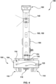
- the autonomous mobile robot 100 according to and performing at least some non-limiting examples of the present technology is illustrated.
- the autonomous mobile robot 100 also referred to herein as the autonomous mobile robot 100, includes a mobile robot base 105, also referred to as the base 105, for providing movement of the autonomous mobile robot 100.
- the base 105 provides a support structure for components of the autonomous mobile robot 100, as well as the movement of the autonomous mobile robot 100.
- the base 105 includes a main body 104.
- the main body 104 is cylinder, with a diameter greater than its height for stability. It is contemplated that the body 104 could be implemented in different forms.
- the base 105 includes a charging module 106 (shown schematically) disposed in the body 104.
- the charging module 106 includes battery and charging-related electronic components (not separately indicated) for providing power to the components of the autonomous mobile robot 100.
- the charging module 106 is configured and arranged to connect to the robot charging station 95 to recharge the battery as required.
- the robot base 105 also includes electric motors 108 (shown schematically) operatively connected to the charging module 106 and a plurality of ground-engaging elements 110, specifically wheels 110.
- the wheels 110 are operatively connected to the motors 108 to be driven thereby.
- the exact number of motors 108 and wheels 110 may vary between different examples and embodiments and it not meant to be limited to the illustrated arrangement.
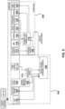
- the robot base 105 includes a navigation and mapping controller 112 communicatively connected to the motors 108 for directing and driving the autonomous mobile robot 100 through the datacenter 10.
- the robot base 105 further includes a plurality of sensors communicatively connected to the controller 112 to provide navigational and environmental information to the controller 112.
- the base 105 includes an inertial measurement unit (IMU) 116 (shown schematically) communicatively connected to the controller 112 and disposed within the base body 104.
- the IMU 116 is formed from a printed circuit board (PCB), MEMS-based gyroscope and three-axis accelerometer (not separately identified), although the specific implementation of the IMU 116 could vary.
- the IMU 116 measures acceleration, angular speed, and the orientation of the autonomous mobile robot 100 in space.
- the IMU 116 generally includes a signal processing circuit communicatively connected to the controller 112 for providing raw or treated spatial or kinetic data to the controller 112.
- the base 105 includes two LIDAR assemblies 118 communicatively connected to the controller 112 for detecting objects and obstacles surrounding the autonomous mobile robot 100 in order to map the surroundings for navigation.
- one LIDAR assembly 118 is connected to and disposed in an upper portion of the base body 104 and the other LIDAR assembly 118 is connected to and disposed below the base body 104, but different placement of one or both assemblies 118 are contemplated in different examples.
- Each LIDAR assembly 118 has an imaging region 119 with a 360° lateral field of view and a range of approximately 16 meters, as is illustrated in Figure 6 . Depending on specific choice of LIDAR assembly, the exact imaging range and/or field of view could vary in different examples.
- the base 105 also includes five ultrasonic sensors 120 communicatively connected to the controller 112.
- the ultrasonic sensors 120 are integrated into the exterior walls of the base body 104, with the ultrasonic sensors 120 being arranged to provide a sensing region 121 with a 360° field of view around the autonomous mobile robot 100.
- the sensing region 121 has a sensing range of approximately 4 meters from the base 105.
- the ultrasonic sensors 120 thus provide obstacle detection around the autonomous mobile robot 100, although information from the sensors 120 could also be integrated into mapping by the autonomous mobile robot 100.
- the number and capabilities of the ultrasonic sensors 120 could vary.
- the base 105 further includes wheel encoders 122 (shown schematically) for measuring movement of the wheels 110 in order to monitor distance traveled by the autonomous mobile robot 100.
- Each wheel encoder 122 measures the rotations of a corresponding wheel 110, which provide information on both a distance traveled by each wheel 110 (with the wheel radius being known), as well as the relative movement between wheels 110.
- the wheel encoders 122 are communicatively connected to the controller 112 and disposed in the base body 104. Depending on the example, it is contemplated that the wheel encoders 122 could be omitted in some cases.
- the base 105 also includes four infrared sensors 114 communicatively connected to the controller 112, via the charging module 106.
- the infrared sensors 114 are disposed on a forward side of the base 105 in order to sense a small region in front of the autonomous mobile robot 100 (when moving in a generally forward direction).
- an infrared sensing region 115 extends a short distance generally forward from the infrared sensors 114.
- the infrared sensors 114 serve to detect the charging base 95, when in close proximity to the base 95, and to properly position the autonomous mobile robot 100 relative to the charging base 95 in order to autonomously connect the autonomous mobile robot 100 to the charging base 95 for charging.
- the infrared sensors 114 could be omitted, disposed on a backward side of the base 105 in order to sense a small region behind the autonomous mobile robot 100 (when moving in a generally forward direction) or exchanged for different sensing technology for positioning the robot 110 relative to the charging base 95.
- the base 105 further includes a camera 124, also referred to as a depth camera 124, disposed on a top surface of the base body 104.
- a camera 124 also referred to as a depth camera 124, disposed on a top surface of the base body 104.
- the camera 124 provides a live and/or recorded view from a front side of the autonomous mobile robot 100 to an operator of the autonomous mobile robot 100.
- the autonomous mobile robot 100 includes a rigid member 140, also referred to as the post 140, connected to and extending generally vertically upward from the base 105.
- the post 140 supports a variety of peripheral components of the autonomous mobile robot 100, as will be described in more detail below.
- the post 140 is generally rectangular and defines therein a series of slots for receiving and/or connecting components. It is contemplated that the post 140 could be implemented in a variety of forms, including but not limited to a cylindrical form. It is also contemplated that more than one post could be included in the autonomous mobile robot 100, for example for supporting different peripheral components on different posts.
- the autonomous mobile robot 100 further includes a system manager 180, also referred to as an embedded computer 180 or a controller 180, for managing operation of the autonomous mobile robot 100, the controller 180 being communicably connected to the navigation and mapping controller 112.
- the computer 180 has a processor unit (not shown) for carrying out executable code, and hard disk storage 150, also referred to as a memory unit 150, operatively connected to the controller 180 that stores, inter alia, the executable code in a non-transitory medium (not shown) included in the storage 150.
- the processor unit includes one or more processors for performing processing operations that implement functionality of the controller 180.
- the processor unit may be a general-purpose processor or may be a specific-purpose processor comprising one or more preprogrammed hardware or firmware elements (e.g., application-specific integrated circuits (ASICs), electrically erasable programmable read-only memories (EEPROMs), etc.) or other related elements.
- the non-transitory medium of the storage 150 may be a semiconductor memory (e.g., read-only memory (ROM) and/or random-access memory (RAM)), a magnetic storage medium, an optical storage medium, and/or any other suitable type of memory. Management of the autonomous mobile robot 100 according to methods of the present technology will be described in more detail below.
- the autonomous mobile robot 100 includes a Wi-Fi antenna/router 155 communicatively and operatively connected to the controller 180.
- the Wi-Fi antenna/router 155 provides wireless communication between the autonomous mobile robot 100 (and/or the controller 180 of the autonomous mobile robot 100) and related systems, such as an external controller for an operator. Depending on the example, it is contemplated that the autonomous mobile robot 100 could communicate with a central controller via the Wi-Fi antenna/router 155.
- the autonomous mobile robot 100 includes a human-machine interface (HMI) 160.
- the HMI 160 is disposed on a top portion of the post 140. While the HMI 160 is arranged in a position to facilitate interaction by the user, it is contemplated that the HMI 160 could be differently placed on the post 140.
- the HMI 160 includes a touch screen 164 for presenting information to the user and for receiving touch commands from the user.
- the autonomous mobile robot 100 could receive commands only via wireless communication, including but not limited to the Wi-Fi antenna/router 155. In some such cases, the HMI 160 and/or the touchscreen 164.
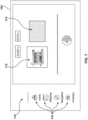
- FIG. 7 illustrates one non-limiting example of a control graphic user interface (GUI) 170 on the touch screen 164.
- the control GUI 170 is one non-limiting example of a software-implemented program for providing information to the user and providing an interface for receiving user commands.
- the control GUI 170 presents a computer-generated map 172 of the structure surveyed by the autonomous mobile robot 100, in this case the datacenter 10.
- the map 172 could be presented in a variety of forms, including but not limited to: an architectural plan and/or a theoretical map saved to the storage 150, and a map created and/or updated by the autonomous mobile robot 100 during exploration of the structure.
- the control GUI 170 also presents an image from the camera 124 (shown schematically) in order to illustrate the region in front of the autonomous mobile robot 100 to the user.
- the control GUI 170 also includes a variety of control functions selectable via a plurality of icons 176.
- the control functions could vary depending on the particular example of the autonomous mobile robot 100 or needs of the structure surveyed thereby.
- the control functions could include, but are not limited to: a structure mapping function, a robot navigation function, an inventory activation function, and a structure monitoring function.
- the controller 180, the control GUI 170, and components of the autonomous mobile robot 100 are operated using a robot operating system (ROS) according to a publisher/subscriber model.
- the controller 180 is communicatively connected to a plurality of nodes via the Wi-Fi antenna/router 155.
- the controller 180 is implemented as a remote Next Unit of Computing module (NUC) communicably connected to the base 105.
- NUC Next Unit of Computing module
- the controller 180 may be remotely connected to the base 105 and components thereof using the Wi-Fi antenna/router 155 for transmitting signals.
- the controller 180 may also be communicably connected to the base 105 and components thereof using Ethernet protocol for transmitting signals.
- different control programming is contemplated.
- the autonomous mobile robot 100 further includes at least two cameras and an inventory module that, upon being executed by the controller 180, causes autonomous mobile robot 100 to take inventory of objects in the data center 10 based on data provided by the at least two cameras.
- the at least two cameras include a first camera 182 and a second camera 184.
- the cameras 182, 184 may be Red-Green-Blue (RGB) cameras, Red-Green-Blue-Depth (RGBD) cameras, monochromatic cameras, or any other types of cameras that may provide data suitable for being used by the inventoring module 174.
- the first camera 182 has a lower image resolution than the second camera 184 such that data provided by the first camera 182 may be manipulated by any data processing system (e.g. the controller 180) with less computing resources.
- Processing of the data provided by the first camera 182 may thus be substantially faster than processing of the data provided by the second camera 184.
- the data provided by the second camera 184 include more information about entities imaged by the second camera 184, given that an image resolution of the second camera 184 is substantially higher.
- the first image resolution is 640x480 (i.e. 640 pixels across a width of a picture capture by the first camera 184, and 480 pixels along a height of said picture) and the second image resolution is 4032x3040.
- the second image resolution is thus more than six times higher than the first image resolution. Execution of the inventoring module 174 is described in greater details here further below with respect to Figures 9 to 11 .
- the autonomous mobile robot 100 may comprise a plurality of first cameras 182 and a plurality of second cameras 184.
- a plurality of point of views may thus be provided by the pluralities of cameras 182, 184.
- the plurality of first cameras 182 operate similarly to the described single first camera 182 and in a simultaneous manner with one another.
- the plurality of second cameras 184 operate similarly to the described single second camera 184 and in a simultaneous manner with one another.
- functions of the first and second cameras 182, 184 are performed by a unique camera that may selectively capture images at the first and second image resolutions.
- said unique camera is a RASPBERRY TM PI HQ camera having a 90° horizontal field of view (HFOV) lens.
- the autonomous mobile robot 100 takes inventory of a plurality of objects within a structure.
- the structure is the datacenter 10 and the plurality of objects is a plurality of servers housed in the racks 50 of the datacenter 10. It is contemplated that the structure and the plurality of objects may differ from the datacenter 10 and the servers thereof respectively in alternative examples.
- any system variation configured to distribute perform any inventory of a plurality of object in a structure can be adapted to execute examples of the present technology, once teachings presented herein are appreciated.
- Figure 8 illustrates a plurality of objects of a datacenter to be observed by the present technology. More specifically, Figure 8 depicts eight (8) electronic equipment modules 55 hosted in one of the racks 50 of the data center 10. It should be understood that the rack 50 may host a different number of electronic equipment modules 55 or other computer processing systems.
- each electronic equipment module 55 includes a support unit 57 and electronic equipment such as a server or other electronic equipment (e.g., networking equipment) supported by the support unit 57.
- the support unit 57 may provide connecting means for connecting the electronic equipment module 55 to the rack 50.
- the rack 50 may include vertical walls 24 laterally spaced from one another so as to define a housing section therebetween in which the electronic equipment modules 55 can be housed.
- the support unit 57 is connected to and/or supported by an equipment support 27.
- the equipment supports 27 are connected to each vertical wall 24 and extend perpendicular thereto.
- a mounting of the electronic equipment modules 55 within the rack 50 is not limitative, other means for connecting the electronic equipment modules 55 to the rack 50 are contemplated in alternative examples.
- the rack 50 may for example be a 19-inch, standard-size rack having dimensions as defined in the EIA/ECA-310-5 E "Cabinets, Racks, Panels, And Associated Equipment" standard.
- the rack 50 is a server rack and the electronic equipment modules 55 housed thereby are server modules or related functional modules (e.g., networking or power supply modules).
- the electronic equipment modules 55 are disposed in the rack 50 in a same manner for each electronic equipment module 55 to form a column of similarly looking electronic equipment modules 55.
- the support unit 57 of each electronic equipment module 55 includes a front panel 59.
- An indicator 62 is disposed on the front panel 59, which may be an electronic equipment module light (e.g. an Light-Emitting Diode (LED)) for example, for indicating, when lit, that electronic components of the corresponding electronic equipment module 55 are electrically powered.
- the indicator 62 may be used to indicate presence and/or position of the electronic equipment module 55 in the rack 50.
- An inventory label 64 is also disposed on the front panel 59.
- the inventory label 64 may include texts, pictures, bar codes, QR-codes, or any other two-dimensional or three-dimensional indications comprising information about hardware characteristics, software characteristics and/or an identifier of the corresponding electronic equipment module 55. As such, any system suitable to read or scan the inventory label 64 may access said information about the corresponding electronic equipment module 55.
- Figure 9 schematically depicts the autonomous mobile robot 100 taking inventory of the plurality of electronic equipment modules 55. As depicted on Figure 9 , the autonomous mobile robot 100 moves in a robot transport path 70 (e.g. an aisle of the data center 10) along a row of racks 50.
- a robot transport path 70 e.g. an aisle of the data center 10.
- the controller 180 may use a navigation planner such as "move_base” algorithm from Robot Operating System (ROS) software library to provide global and local planners to the autonomous mobile robot 100, coupled with “teb_local_planner” from the ROS software library that may optimize a trajectory of the autonomous mobile robot 100 with respect to a trajectory execution time, separation from detected obstacles and compliance with kinodynamic constraints at runtime.
- the navigation planner may thus plan navigation and further cause the autonomous mobile robot 100 to navigate along a generated path in the data center 10.
- the autonomous mobile robot 100 uses sensors such as the inertial measurement unit (IMU) 116, the LIDAR assemblies 118, the ultrasonic sensors 120, the infrared sensors 114 and the camera 124 to receive environmental information about an environment of the autonomous mobile robot 100.
- the LIDAR assemblies 118 may detect presence of the row of racks 50 and provide the controller 180 with data including information about a distance between said row of racks 50 and the autonomous mobile robot 100 such that the controller 180 may cause the autonomous mobile robot 100 to navigate at a given distance of the row of racks 50. This may increase a relative safety level of the autonomous mobile robot 100 and the racks 50 by reducing a probability of collision between the two.
- data provided by the camera 124 may be inputted in a object-detection algorithm to detect presence of a human entity (e,g, an operator of the data center), an open door of a rack 50, a forklift, or any other object that may be suitably detected by a given object-detection algorithm.
- a human entity e,g, an operator of the data center
- the controller 180 is provided with the environmental information including information about entities present in a vicinity of the autonomous mobile robot 100 such that the controller 180 may cause and/or adjust a navigation thereof.
- the controller 180 accesses a plan of the data center 10 and causes the autonomous mobile robot 100 to displace through the structure, displacements of the autonomous mobile robot 100 being based at least in part on the plan of the structure.
- the controller 180 executes the inventoring module 174. More specifically, the controller 180 causes the first camera 182 to capture positioning images at the first image resolution. For example, the first camera 182 may continuously capture images (e.g. with an imaging rate of five images per second), the first camera 182 being oriented toward the racks 50. In some examples, the first camera provides a stream of images at the first image resolution to the controller 180. Images captured by the first camera 182 are indicative of a position of the autonomous mobile robot 100 relatively to the racks 50, as may thus be referred to as "positioning images". For example and without limitations, the first camera 182 may be fixedly attached to the post 140, such that the first camera 182 is oriented toward the racks 50 when the autonomous mobile robot 100 navigates along the racks 50 on the robot transport path 70.
- the controller 180 Upon receiving the positioning images, the controller 180 processes the positioning images and determine presence of a predetermined landmark, such as the indicator 62.
- the controller 180 may use a form-identifying image treatment algorithm to detect presence of the predetermined landmark in the positioning image.
- the image of the predetermined landmark may be, for example and without limitation, a shape, a contoured shape, a pattern, a color (e.g. RGB value, HSL value), a variation of color (e.g. gradient of color), a brightness and/or any visual characteristics or combination thereof of a pixel or a group of pixels of the captured positioning image.
- the first camera 182 is an RGB camera and the controller 180 detects presence of the image of the predetermined landmark upon detecting a circular form having an RGB value within an RGB value range and a brightness value above a predetermined threshold.
- detection of the image of the predetermined landmark is indicative of an imaging, by the first camera 182, of one of the indicators 62 of the electronic equipment modules 55.
- the controller 180 identifies the positioning image containing the predetermined landmark as a landmarked positioning image.
- the autonomous mobile robot 100 is in a position denoted P1 while the first camera 182 captures images of the racks 50.
- the controller 180 may identify a landmarked positioning image while the autonomous mobile robot 100 is positioned in P1.
- the controller 180 uses the form-identifying image treatment algorithm to detect an image of a predetermined repeating landmark and identifies a positioning image as the landmarked positioning image in response to the predetermined repeating landmark being detected in said positioning image.
- the indicators 62 of the electronic equipment module 55 of a same rack 50 form a column 90 of indicators, which can be referred to as a predetermined repeating landmark 90 given that it includes a plurality of the aforementioned predetermined landmarks.
- the form-identifying image treatment algorithm is used by the controller 180 to search for a predetermined repeating form pattern in the given positioning image.
- the positioning image is further identified as a landmarked positioning image in response to successfully finding the predetermined repeating form pattern in the given image.
- the first camera 182 is a RGB camera and the controller 180 detects presence of the image of the predetermined repeating landmark upon detecting a column of circular forms having an RGB value within an RGB value range and a brightness above a predetermined threshold.
- the predetermined repeating form pattern is a plurality of occurrences of circular forms having a RGB value within a RGB value range and a brightness value above a predetermined threshold in the positioning image, the circular forms being aligned along a same direction that is, in this example, a generally vertical line.
- detection of the image of the predetermined landmark is indicative of an imaging, by the first camera 182, of a column of the indicators 62 extending substantially vertically of the electronic equipment modules 55 of a same rack 50.
- the controller 180 identifies the positioning image containing the predetermined repeating landmark as a landmarked positioning image.
- the controller 180 may cause the autonomous mobile robot 100 to stop and determines a position of the autonomous mobile robot 100 relatively to the predetermined landmark. To do so, the controller 180 may, for example, use data provided by the IMU 116, the LIDAR assemblies 118, the ultrasonic sensors 120, the infrared sensors 114 and the camera 124. It is to be understood that in this context, the relative positions of the autonomous mobile robot 100 and the predetermined landmark include information about a location and an orientation of the autonomous mobile robot 100 relatively to the predetermined landmark and the rack 50.
- the controller 180 further determines a data collection position relatively to the predetermined landmark or the predetermined repeating landmark.
- the data collection position and determination thereof are based on the position of the autonomous mobile robot 100 during acquisition of the landmarked positioning image (i.e. P1 in this example).
- Information about the data collection position relatively to the predetermined landmark or the predetermined repeating landmark may be accessed by the controller 180 such that the controller 180 may cause the autonomous mobile robot 100 to reach said data collection position starting from P1.
- the controller 180 may determine that P1 is 2 meters away in a first direction from the predetermined landmark.
- the controller 180 may access information about the data collection position indicative that a location associated with the data collection position is 0.7 meter away from the predetermined landmark, and an orientation of the autonomous mobile robot 100 associated with the data collection position is a second predetermined direction.
- the controller 180 may thus determine the location and orientation of the data collection position relatively to P1 and cause the autonomous mobile robot 100 to reach said data collection position. It is to be understood that in this context, the autonomous mobile robot 100 is said to navigate to a predetermined data collection position in cases where a location and an orientation relative to the predetermine landmark are adjusted according to a predetermined location and angular orientation such that the autonomous mobile robot 100 is in the data collection position.
- the controller 180 upon identifying the landmarked positioning image and relative positions of the autonomous mobile robot 100 and the predetermined landmark or the predetermined repeating landmark, the controller 180 cause the autonomous mobile robot 100 to adjust a position (i.e. location and orientation of the autonomous mobile robot 100) by navigating to the data collection position.
- a position i.e. location and orientation of the autonomous mobile robot 100
- the autonomous mobile robot 100 is in the data collection position denoted P2 and may have adjusted a location and/or an orientation of autonomous mobile robot 100 relatively to the predetermined landmark.
- the controller 180 causes the autonomous mobile robot 100 to stop once the autonomous mobile robot 100 is in the data collection position.
- the controller 180 cause the second camera 184 to acquire at least one inventory image at the second image resolution.
- the data collection position P2 is defined such that a field of view of the second camera 184 include the inventory labels 64 when the autonomous mobile robot 100 is in the data collection image P2.
- the inventory labels 64 of the 55 of a same rack 50 form a label column 80.
- the field of view of the second camera 184 is set such that the inventory image includes the label column 80.
- the second camera 184 may be fixedly attached to the post 140 and adjacent to the first camera 182.
- the controller 180 further extracts, from the inventory image, the plurality of inventory labels 64.
- the controller 180 may transmit the extracted inventory labels or data red or scanned therefrom to an operator device of an operator of the data center 10.
- the controller 180 may also access a database (e.g. using the Wi-Fi antenna/router 155) to access information about the electronic equipment modules 55 such as hardware characteristics, software characteristics and/or identifiers of the corresponding electronic equipment modules 55 based on the extracted inventory labels 64.
- Inventory of the electronic equipment modules 55 of a rack 50 may be performed.
- the autonomous mobile robot 100 may further proceed with navigating along the robot transport path 70 and take inventory of another rack 50.
- the autonomous mobile robot 100 may successively take inventory of the electronic equipment modules 55 of consecutive racks 50 along the robot transport path 70.
- the autonomous mobile robot 100 may also receive instructions to navigate to a specific rack 50 within the data center 10 and take inventory of the electronic equipment modules 55 therefrom.
- Figures 8 to 10 illustrates the autonomous mobile robot 100 operating in the data center 10 for taking inventory of electronic equipment modules 55 and more specifically, of servers within the data center 10.
- any system variation configured to taking inventory of a plurality of objects within a structure can be adapted to execute examples of the present technology, once teachings presented herein are appreciated.
- Examples and embodiments of the present technology can be equally applied to other types of the structure and other types of objects to take inventory for.
- the structure may be a warehouse, a mall, a shipping platform, a library, or any other structure where taking inventory may be suitably performed by the autonomous mobile robot 100.
- the objects may be labelled items, shops, parcels, books, or any other objects that may be detected by the autonomous mobile robot 100.
- Figure 11 is a flow diagram of a method 1000 for taking inventory of a plurality of objects within a structure according to some examples of the present technology.
- the method 1000 or one or more steps thereof may be performed by an autonomous mobile robot, in the present example by the autonomous mobile robot 100.
- the method 1000 or one or more steps thereof may be, for example and without limitation, executed by the controller 180 or a remote controller communicably connected with the autonomous mobile robot 100.
- the method 1000 or one or more steps thereof may be embodied in computer-executable instructions that are stored in a computer-readable medium, such as a non-transitory mass storage device, loaded into memory and executed by a CPU.
- the steps of the method 1000 are executed by a controller of the autonomous mobile robot, such as controller 180 of the autonomous mobile robot 100.
- Some steps or portions of steps in the flow diagram may be omitted or changed in order.
- the method 1000 begins, at step 1005, with causing the autonomous mobile robot to navigate through at least a portion of the structure.
- the structure is a data center such as the data center 10.
- the controller of the autonomous mobile robot accesses a map or a plan of the structure and further causes the autonomous mobile robot to displace through the structure.
- the displacements of the autonomous mobile robot may be based at least in part on the plan of the structure.
- the controller may use a navigation planner to determine the displacements of the autonomous mobile robot such as the aforementioned"move_base” and “teb_local_planner” algorithms.
- the controller may also use the "map_server” algorithm from the ROS software library to access and/or retrieve a map of the structure from a server or a database communicably connected to the controller.
- the controller of the autonomous mobile robot may acquire environmental information using at least one sensor of the autonomous mobile robot.
- the controller may communicate with sensors of the autonomous mobile robot such as the inertial measurement unit (IMU) 116, LIDAR assemblies 118, ultrasonic sensors 120, infrared sensors 114 and camera 124, and receive data therefrom. Said data may include navigational and environmental information.
- the controller may further base displacements of the autonomous mobile robot at least in part on the environmental information.
- the method 1000 continues, at step 1010, with causing, while navigating through the portion of the structure, at least one camera of the autonomous mobile robot to acquire a plurality of positioning images at a first image resolution.
- the at least one camera may be the first camera 182.
- the first image resolution may be, for example and without limitation, 640x480.
- the at least one camera images at least one rack of the datacenter, such as the rack 50 to acquire the positioning images.
- the autonomous mobile robot includes a plurality of cameras that may be identical to the first camera 182.
- the controller of the autonomous mobile robot causes the plurality of cameras to acquire a plurality of sets of positioning images.
- the plurality of cameras simultaneously image different areas of the structure.
- the cameras may simultaneously image a front side of the rack 50 depicted on Figure 8 .
- the method 1000 further continues, at step 1015, with determining that at least one positioning image of the plurality of positioning images contains an image of a predetermined landmark.
- the controller of the autonomous mobile robot may process a given image using a form-identifying image treatment algorithm to search for an image of the predetermined landmark for each positioning image.
- the form-identifying image treatment algorithm may be, for example and without limitation, YOLOv5 available on GitHub TM platform. Other algorithms may be used in addition to or instead of the YOLOv5 algorithm.
- the controller may detect presence of the image of the predetermined landmark upon detecting a circular form having a RGB value within an RGB value range and a brightness value above a predetermined threshold in a given positioning image.
- the positioning image containing the image of the predetermined landmark may be referred to as a landmarked positioning image.
- the controller may identify a positioning image as a landmarked positioning image upon determining presence of a predetermined repeating landmark in said positioning image.
- the controller of the autonomous mobile robot may use the form-identifying image treatment algorithm to search for a predetermined repeating form pattern in the given image for each of the plurality of positioning images.
- the predetermined repeating form pattern may be a column of circular forms having a RGB value within a RGB value range and a brightness value above a predetermined threshold.
- the column of circular forms may correspond to the column 80 of indicators such as electronic equipment module light (e.g. LEDs) of the electronic equipment modules 55 of a same rack 50.
- the circular forms are expected to correspond to the indicators 62 (e.g. LEDs) as described in Figure 8 .
- the controller identifies the given image as containing the image of the predetermined repeating landmark.
- the method 1000 further continues, at step 1020, with causing, in response to determining that the at least one positioning image of the plurality of positioning images contains the image of the predetermined landmark, the autonomous mobile robot to reach a predetermined data collection position. More specifically, the controller may access information about a location and an orientation that the autonomous mobile robot should reach relatively to the predetermined landmark. Determination of the location of the predetermined data collection position relatively to a current location of the autonomous mobile robot is based at least in part on a position of the autonomous mobile robot during acquisition of the landmarked positioning image. In an example, the controller causes the autonomous mobile robot to come to a stop in an imaging position relative to the predetermined landmark.
- the method 1000 further continues, at step 1025, with causing the at least one camera of the autonomous mobile robot to acquire at least one inventory image at a second image resolution, the second image resolution being greater than the first image resolution.
- the second image resolution may be, for example and without limitation, 4032x3040.
- the autonomous mobile robot includes a first camera (e.g. the first camera 124) to acquire images at the first image resolution and a second camera (e.g. the second camera 184) to acquire images at the second image resolution.
- Data provided by the first camera may thus be manipulated by any data processing system (e.g. the controller 180) with less computing resources compared to data provided by the second camera. Processing of the data provided by the first camera may thus be substantially faster than processing of the data provided by the second camera.
- data provided by the second camera include more information due to the relative higher image resolution.
- acquiring the inventory images includes imaging inventory labels, such as the inventory labels 64, disposed on a front surface of the electronic equipment modules 55. More specifically, it is expected that the inventory labels are included in a field of view of the second camera when the autonomous mobile robot is in the data collection position.
- the controller of the autonomous mobile robot causes the at least one camera to acquire the plurality of positioning images at the first image resolution and the at least one inventory image at the second image resolution at a same distance to the plurality of objects.
- the method 1000 ends, at step 1030, with extracting from the at least one inventory image, a plurality of inventory labels, each inventory label relating to a corresponding object of the plurality of objects within the structure.
- the inventory labels may be, for example and without limitation, similar or having the same characteristics to the inventory labels 64 of the electronic equipment modules 55.
- the controller may extract texts, pictures, bar codes, QR-codes, or any other two-dimensional or three-dimensional indications of the inventory labels comprising information about hardware characteristics, software characteristics and/or an identifier of the corresponding electronic equipment module 55.
Landscapes
- Engineering & Computer Science (AREA)
- Physics & Mathematics (AREA)
- General Physics & Mathematics (AREA)
- Automation & Control Theory (AREA)
- Aviation & Aerospace Engineering (AREA)
- Radar, Positioning & Navigation (AREA)
- Remote Sensing (AREA)
- Robotics (AREA)
- Business, Economics & Management (AREA)
- Mechanical Engineering (AREA)
- Theoretical Computer Science (AREA)
- Multimedia (AREA)
- Computer Vision & Pattern Recognition (AREA)
- Economics (AREA)
- Signal Processing (AREA)
- Electromagnetism (AREA)
- Operations Research (AREA)
- Quality & Reliability (AREA)
- General Business, Economics & Management (AREA)
- Tourism & Hospitality (AREA)
- Accounting & Taxation (AREA)
- Finance (AREA)
- Development Economics (AREA)
- Strategic Management (AREA)
- Entrepreneurship & Innovation (AREA)
- Human Resources & Organizations (AREA)
- Marketing (AREA)
- Artificial Intelligence (AREA)
- Evolutionary Computation (AREA)
- Mathematical Physics (AREA)
- Fuzzy Systems (AREA)
- Software Systems (AREA)
- Control Of Position, Course, Altitude, Or Attitude Of Moving Bodies (AREA)
- Health & Medical Sciences (AREA)
- Game Theory and Decision Science (AREA)
- Medical Informatics (AREA)
- Manipulator (AREA)
Claims (15)
- Procédé (1000) pour la prise d'inventaire d'une pluralité d'objets au sein d'une structure, le procédé comprenant :le fait d'amener un robot mobile autonome (100) à naviguer à travers au moins une partie de la structure ;lors de la navigation à travers la partie de la structure, le fait d'amener au moins une caméra (182, 184) du robot mobile autonome (100) à acquérir une pluralité d'images de positionnement à une première résolution d'image ;la détermination qu'au moins une image de positionnement de la pluralité d'images de positionnement contient une image d'un point de repère prédéterminé ;en réponse à la détermination que l'au moins une image de positionnement de la pluralité d'images de positionnement contient l'image du point de repère prédéterminé, le fait d'amener le robot mobile autonome (100) à naviguer vers une position de collecte de données prédéterminée, la position de collecte de données prédéterminée étant basée au moins en partie sur une position du robot mobile autonome (100) pendant l'acquisition de l'au moins une image de positionnement ;le procédé étant caractérisé en ce que le procédé comprend également :le fait d'amener l'au moins une caméra (182, 184) du robot mobile autonome (100) à acquérir au moins une image d'inventaire à une seconde résolution d'image, la seconde résolution d'image étant supérieure à la première résolution d'image ; etl'extraction, à partir de l'au moins une image d'inventaire, d'une pluralité d'étiquettes d'inventaire (64), chaque étiquette d'inventaire (64) se rapportant à un objet correspondant de la pluralité d'objets au sein de la structure.
- Procédé (1000) selon la revendication 1, dans lequel le fait d'amener le robot mobile autonome (100) à naviguer vers la position de collecte de données prédéterminée comprend :
le fait d'amener le robot (100) à s'arrêter dans une position d'imagerie par rapport au point de repère prédéterminé. - Procédé (1000) selon la revendication 1 ou 2, dans lequel le fait d'amener le robot mobile autonome (100) à naviguer à travers au moins la partie de la structure comprend :le fait d'accéder à un plan de la structure ; etle fait d'amener le robot mobile autonome (100) à se déplacer à travers la structure, les déplacements du robot mobile autonome (100) étant basés au moins en partie sur le plan de la structure.
- Procédé (1000) selon la revendication 3, dans lequel le fait d'amener le robot mobile autonome (100) à se déplacer à travers la structure comprend également l'acquisition d'informations environnementales à l'aide d'au moins un capteur (114, 116, 118, 120, 122, 124) du robot mobile autonome (100), les déplacements du robot mobile autonome (100) étant basés au moins en partie sur les informations environnementales.
- Procédé (1000) selon l'une quelconque des revendications 1 à 4, dans lequel la détermination que l'au moins une image de positionnement contient une image du point de repère prédéterminé comprend la détermination que l'au moins une image de positionnement contient une image d'un point de repère répétitif prédéterminé (90).
- Procédé (1000) selon la revendication 5, dans lequel la détermination que l'au moins une image de positionnement contient l'image du point de repère répétitif prédéterminé (90) comprend :pour chacune de la pluralité d'images de positionnement, le traitement d'une image donnée à l'aide d'un algorithme de traitement d'image d'identification de forme pour rechercher un motif de forme répétitif prédéterminé dans l'image donnée ; eten réponse à la recherche réussie du motif de forme répétitif prédéterminé dans l'image donnée, l'identification de l'image donnée comme contenant l'image du point de repère répétitif prédéterminé (90).
- Procédé (1000) selon la revendication 6, dans lequel :
le traitement de l'image donnée à l'aide de l'algorithme de traitement d'image d'identification de forme comprend :l'identification d'une pluralité de formes circulaires d'une valeur de couleur prédéterminée dans l'image donnée ; eten réponse à la pluralité de formes circulaires formant une ligne généralement verticale, l'identification de l'image donnée comme contenant l'image du point de repère répétitif prédéterminé (90). - Procédé (1000) selon l'une quelconque des revendications 1 à 7, dans lequel :
le fait d'amener l'au moins une caméra (182, 184) à acquérir la pluralité d'images de positionnement à la première résolution d'image comprend :
le fait d'amener une pluralité de caméras du robot mobile autonome (100) à acquérir une pluralité d'ensembles d'images de positionnement, la pluralité de caméras étant configurée et agencée pour imager simultanément différentes zones de la structure. - Procédé (1000) selon l'une quelconque des revendications 1 à 7, dans lequel le fait d'amener l'au moins une caméra (182, 184) du robot mobile autonome (100) à acquérir la pluralité d'images de positionnement à la première résolution d'image et le fait d'amener l'au moins une caméra (182, 184) à acquérir l'au moins une image d'inventaire à la seconde résolution d'image se produit avec l'au moins une caméra (182, 184) à une même distance de la pluralité d'objets.
- Procédé (1000) selon l'une quelconque des revendications 1 à 9, dans lequel :le fait d'amener le robot mobile autonome (100) à naviguer à travers la structure comprend le fait d'amener le robot mobile autonome (100) à naviguer à travers un centre de données (10) ;le fait d'amener l'au moins une caméra (182, 184) à acquérir la pluralité d'images de positionnement comprend l'imagerie d'au moins un rack (50) du centre de données (10) ;la détermination que l'au moins une image de positionnement contient l'image du point de repère prédéterminé comprend la détermination que l'au moins une image de positionnement contient une image d'une pluralité de lumières de module d'équipement électronique (62) ; etl'extraction de chaque étiquette d'inventaire comprend l'extraction d'une pluralité de codes à barres, chaque code à barres identifiant un module d'équipement électronique correspondant de l'au moins un rack (50).
- Support non transitoire lisible par ordinateur comprenant des instructions lisibles par ordinateur qui, une fois exécutées par un système, amènent le système à réaliser le procédé (1000) selon l'une quelconque des revendications 1 à 10.
- Robot mobile autonome (100) pour la prise d'inventaire dans une structure, le robot mobile autonome (100) comprenant :une base de robot mobile (105) pour assurer le mouvement du robot mobile autonome (100) ;un élément rigide (140) relié à la base de robot mobile (105) et se prolongeant au moins partiellement vers le haut à partir de celle-ci ;au moins une caméra (182, 184) reliée de manière fixe à l'élément rigide (140), l'au moins une caméra (182, 184) étant configurée et agencée pour acquérir des images d'une pluralité d'objets au sein de la structure ; etun système de dispositif de commande connecté de manière communicative à la base de robot mobile (105) et à l'au moins une caméra (182, 184), le système de dispositif de commande étant configuré pour :
commander le déplacement du robot mobile autonome (100) à l'aide de la base de robot mobile (105), le robot mobile autonome (100) étant caractérisé en ce que le dispositif de commande est également configuré pour :
commander le fonctionnement de l'au moins une caméra (182, 184) pour :acquérir une pluralité d'images de positionnement à une première résolution d'image ; etacquérir, en réponse à la détermination que l'au moins une image de positionnement de la pluralité d'images de positionnement contient une image d'un point de repère prédéterminé, au moins une image d'inventaire à une seconde résolution d'image, la seconde résolution d'image étant supérieure à la première résolution d'image, le dispositif de commande étant configuré pour amener le robot mobile autonome (100) à naviguer vers une position de collecte de données prédéterminée, la position de collecte de données prédéterminée étant basée au moins en partie sur une position du robot mobile autonome (100) pendant l'acquisition de l'au moins une image de positionnement ; etextraire, à partir de l'au moins une image d'inventaire, une pluralité d'étiquettes d'inventaire (64), chaque étiquette d'inventaire (64) se rapportant à un objet correspondant de la pluralité d'objets au sein de la structure. - Robot mobile autonome (100) selon la revendication 12, dans lequel :l'au moins une caméra (182, 184) comprend une pluralité de caméras reliées à l'élément rigide (140) ; etchaque caméra de la pluralité de caméras est configurée et agencée pour imager simultanément une partie différente de la structure.
- Robot mobile autonome (100) selon la revendication 13, au moins une caméra de la pluralité de caméras (182, 184) est espacée verticalement d'au moins une autre caméra de la pluralité de caméras.
- Robot mobile autonome (100) selon l'une quelconque des revendications 12 à 14, dans lequel :la structure est un centre de données (10) ; etle robot autonome (100) est configuré et agencé pour imager une pluralité de racks (50) dans le centre de données (10).
Priority Applications (5)
| Application Number | Priority Date | Filing Date | Title |
|---|---|---|---|
| EP22306282.9A EP4332710B1 (fr) | 2022-08-30 | 2022-08-30 | Procédés et robots autonomes pour la prise d'inventaire dans une structure |
| CA3210059A CA3210059A1 (fr) | 2022-08-30 | 2023-08-23 | Methodes et robots autonomes pour la prise d~inventaire dans une structure |
| US18/238,318 US12406228B2 (en) | 2022-08-30 | 2023-08-25 | Methods and autonomous robots for taking inventory in a structure |
| CN202311100986.5A CN117621043A (zh) | 2022-08-30 | 2023-08-29 | 用于在结构中进行盘点的方法和自主式机器人 |
| KR1020230113290A KR20240031114A (ko) | 2022-08-30 | 2023-08-29 | 구조체에서 인벤토리를 파악하기 위한 방법 및 자율 로봇 |
Applications Claiming Priority (1)
| Application Number | Priority Date | Filing Date | Title |
|---|---|---|---|
| EP22306282.9A EP4332710B1 (fr) | 2022-08-30 | 2022-08-30 | Procédés et robots autonomes pour la prise d'inventaire dans une structure |
Publications (2)
| Publication Number | Publication Date |
|---|---|
| EP4332710A1 EP4332710A1 (fr) | 2024-03-06 |
| EP4332710B1 true EP4332710B1 (fr) | 2024-10-02 |
Family
ID=83361318
Family Applications (1)
| Application Number | Title | Priority Date | Filing Date |
|---|---|---|---|
| EP22306282.9A Active EP4332710B1 (fr) | 2022-08-30 | 2022-08-30 | Procédés et robots autonomes pour la prise d'inventaire dans une structure |
Country Status (5)
| Country | Link |
|---|---|
| US (1) | US12406228B2 (fr) |
| EP (1) | EP4332710B1 (fr) |
| KR (1) | KR20240031114A (fr) |
| CN (1) | CN117621043A (fr) |
| CA (1) | CA3210059A1 (fr) |
Families Citing this family (1)
| Publication number | Priority date | Publication date | Assignee | Title |
|---|---|---|---|---|
| US20260111691A1 (en) * | 2024-10-20 | 2026-04-23 | Dell Products L.P. | Computing device rack location identification system |
Family Cites Families (27)
| Publication number | Priority date | Publication date | Assignee | Title |
|---|---|---|---|---|
| WO2005004142A1 (fr) * | 2003-06-30 | 2005-01-13 | Fujitsu Limited | Procede de commande d'un dispositif bibliotheque, programme et dispositif |
| US8117092B2 (en) | 2003-07-09 | 2012-02-14 | Hewlett-Packard Development Company, L.P. | Inventory management of components |
| US7313461B2 (en) * | 2003-11-26 | 2007-12-25 | Hewlett-Packard Development Company, L.P. | Data connectivity with a robotic device |
| US7725212B2 (en) | 2005-10-21 | 2010-05-25 | Hewlett-Packard Development Company, L.P. | Datacenter with automated robotic maintenance |
| US7693757B2 (en) | 2006-09-21 | 2010-04-06 | International Business Machines Corporation | System and method for performing inventory using a mobile inventory robot |
| US9463574B2 (en) * | 2012-03-01 | 2016-10-11 | Irobot Corporation | Mobile inspection robot |
| US9176648B1 (en) | 2012-12-19 | 2015-11-03 | Emc Corporation | Authoring a virtualized data center |
| US9378481B2 (en) * | 2013-09-09 | 2016-06-28 | Level 3 Communications, Llc | System and methods for inventory management of data center equipment contained in server racks |
| US9152149B1 (en) | 2014-06-06 | 2015-10-06 | Amazon Technologies, Inc. | Fiducial markers with a small set of values |
| US9908239B1 (en) | 2014-06-12 | 2018-03-06 | Amazon Technologies, Inc. | Mobile robot system |
| US10509110B2 (en) * | 2015-12-29 | 2019-12-17 | The Boeing Company | Variable resolution light radar system |
| US9908702B2 (en) * | 2016-02-05 | 2018-03-06 | Invia Robotics, Inc. | Robotic navigation and mapping |
| US11087272B2 (en) | 2016-03-29 | 2021-08-10 | Bossa Nova Robotics Ip, Inc. | System and method for locating, identifying and counting items |
| KR102216498B1 (ko) | 2016-05-19 | 2021-02-17 | 심베 로보틱스 인코포레이션 | 상점의 선반 상의 제품의 배치를 추적하기 위한 방법 |
| US10769582B2 (en) * | 2016-06-30 | 2020-09-08 | Bossa Nova Robotics Ip, Inc. | Multiple camera system for inventory tracking |
| US10071856B2 (en) | 2016-07-28 | 2018-09-11 | X Development Llc | Inventory management |
| US10353395B2 (en) | 2016-09-26 | 2019-07-16 | X Development Llc | Identification information for warehouse navigation |
| US10210603B2 (en) * | 2016-10-17 | 2019-02-19 | Conduent Business Services Llc | Store shelf imaging system and method |
| US10331876B2 (en) | 2017-02-24 | 2019-06-25 | Microsoft Technology Licensing, Llc | Automated secure disposal of hardware components |
| JP6912946B2 (ja) | 2017-06-12 | 2021-08-04 | 株式会社野村総合研究所 | 状態判定装置 |
| US11334086B2 (en) * | 2017-09-27 | 2022-05-17 | Intel Corporation | Autonomous robots and methods of operating the same |
| US20190180150A1 (en) * | 2017-12-13 | 2019-06-13 | Bossa Nova Robotics Ip, Inc. | Color Haar Classifier for Retail Shelf Label Detection |
| AU2018203338B2 (en) | 2018-05-14 | 2020-06-25 | Deutsche Post Ag | Autonomous robot vehicle |
| US10935980B2 (en) * | 2018-09-12 | 2021-03-02 | International Business Machines Corporation | Automated maintenance of datacenter computers using mobile robotic manipulators |
| US12437258B2 (en) | 2020-08-12 | 2025-10-07 | Carnegie Mellon University | System and method for identifying products in a shelf management system |
| US11651519B2 (en) | 2020-08-12 | 2023-05-16 | Google Llc | Autonomous 2D datacenter rack imager |
| US20220187844A1 (en) * | 2020-12-14 | 2022-06-16 | Google Llc | Autonomous 3D Datacenter Mapping System |
-
2022
- 2022-08-30 EP EP22306282.9A patent/EP4332710B1/fr active Active
-
2023
- 2023-08-23 CA CA3210059A patent/CA3210059A1/fr active Pending
- 2023-08-25 US US18/238,318 patent/US12406228B2/en active Active
- 2023-08-29 KR KR1020230113290A patent/KR20240031114A/ko active Pending
- 2023-08-29 CN CN202311100986.5A patent/CN117621043A/zh active Pending
Also Published As
| Publication number | Publication date |
|---|---|
| CN117621043A (zh) | 2024-03-01 |
| KR20240031114A (ko) | 2024-03-07 |
| US12406228B2 (en) | 2025-09-02 |
| CA3210059A1 (fr) | 2024-02-29 |
| US20240070611A1 (en) | 2024-02-29 |
| EP4332710A1 (fr) | 2024-03-06 |
Similar Documents
| Publication | Publication Date | Title |
|---|---|---|
| US10949798B2 (en) | Multimodal localization and mapping for a mobile automation apparatus | |
| US11790546B2 (en) | Point cloud annotation for a warehouse environment | |
| US20200150666A1 (en) | Method, system and apparatus for obstacle handling in navigational path generation | |
| AU2019396253B2 (en) | Method, system and apparatus for auxiliary label detection and association | |
| US11450011B2 (en) | Adaptive item counting algorithm for weight sensor using sensitivity analysis of the weight sensor | |
| US11543249B2 (en) | Method, system and apparatus for navigational assistance | |
| US12051252B2 (en) | Location discovery | |
| US11587243B2 (en) | System and method for position tracking using edge computing | |
| US11501455B2 (en) | System and method for position tracking using edge computing | |
| US20240074116A1 (en) | Robot-assisted monitoring of potential heat anomalies in a datacenter rack assemblies | |
| US12406228B2 (en) | Methods and autonomous robots for taking inventory in a structure | |
| US20200182623A1 (en) | Method, system and apparatus for dynamic target feature mapping | |
| US20200191559A1 (en) | Method, system and apparatus for support structure detection | |
| US12318915B2 (en) | Visual guidance for locating obstructed mobile robots | |
| US11327504B2 (en) | Method, system and apparatus for mobile automation apparatus localization | |
| CN113219485B (zh) | 自主3d数据中心映射系统 | |
| US20230177853A1 (en) | Methods and Systems for Visual Item Handling Guidance |
Legal Events
| Date | Code | Title | Description |
|---|---|---|---|
| PUAI | Public reference made under article 153(3) epc to a published international application that has entered the european phase |
Free format text: ORIGINAL CODE: 0009012 |
|
| STAA | Information on the status of an ep patent application or granted ep patent |
Free format text: STATUS: EXAMINATION IS IN PROGRESS |
|
| 17P | Request for examination filed |
Effective date: 20230330 |
|
| AK | Designated contracting states |
Kind code of ref document: A1 Designated state(s): AL AT BE BG CH CY CZ DE DK EE ES FI FR GB GR HR HU IE IS IT LI LT LU LV MC MK MT NL NO PL PT RO RS SE SI SK SM TR |
|
| REG | Reference to a national code |
Ref country code: DE Ref legal event code: R079 Free format text: PREVIOUS MAIN CLASS: G05D0001000000 Ipc: G05D0001244000 Ref document number: 602022006514 Country of ref document: DE |
|
| GRAP | Despatch of communication of intention to grant a patent |
Free format text: ORIGINAL CODE: EPIDOSNIGR1 |
|
| STAA | Information on the status of an ep patent application or granted ep patent |
Free format text: STATUS: GRANT OF PATENT IS INTENDED |
|
| RIC1 | Information provided on ipc code assigned before grant |
Ipc: G05D 111/10 20240101ALI20240521BHEP Ipc: G05D 109/10 20240101ALI20240521BHEP Ipc: G05D 107/70 20240101ALI20240521BHEP Ipc: G05D 105/80 20240101ALI20240521BHEP Ipc: G05D 1/689 20240101ALI20240521BHEP Ipc: G05D 1/244 20240101AFI20240521BHEP |
|
| INTG | Intention to grant announced |
Effective date: 20240618 |
|
| GRAS | Grant fee paid |
Free format text: ORIGINAL CODE: EPIDOSNIGR3 |
|
| GRAA | (expected) grant |
Free format text: ORIGINAL CODE: 0009210 |
|
| STAA | Information on the status of an ep patent application or granted ep patent |
Free format text: STATUS: THE PATENT HAS BEEN GRANTED |
|
| AK | Designated contracting states |
Kind code of ref document: B1 Designated state(s): AL AT BE BG CH CY CZ DE DK EE ES FI FR GB GR HR HU IE IS IT LI LT LU LV MC MK MT NL NO PL PT RO RS SE SI SK SM TR |
|
| REG | Reference to a national code |
Ref country code: GB Ref legal event code: FG4D |
|
| REG | Reference to a national code |
Ref country code: CH Ref legal event code: EP |
|
| REG | Reference to a national code |
Ref country code: DE Ref legal event code: R096 Ref document number: 602022006514 Country of ref document: DE |
|
| P01 | Opt-out of the competence of the unified patent court (upc) registered |
Free format text: CASE NUMBER: APP_51752/2024 Effective date: 20240913 |
|
| REG | Reference to a national code |
Ref country code: IE Ref legal event code: FG4D |
|
| REG | Reference to a national code |
Ref country code: LT Ref legal event code: MG9D |
|
| REG | Reference to a national code |
Ref country code: NL Ref legal event code: MP Effective date: 20241002 |
|
| REG | Reference to a national code |
Ref country code: AT Ref legal event code: MK05 Ref document number: 1728938 Country of ref document: AT Kind code of ref document: T Effective date: 20241002 |
|
| PG25 | Lapsed in a contracting state [announced via postgrant information from national office to epo] |
Ref country code: NL Free format text: LAPSE BECAUSE OF FAILURE TO SUBMIT A TRANSLATION OF THE DESCRIPTION OR TO PAY THE FEE WITHIN THE PRESCRIBED TIME-LIMIT Effective date: 20241002 |
|
| PG25 | Lapsed in a contracting state [announced via postgrant information from national office to epo] |
Ref country code: NL Free format text: LAPSE BECAUSE OF FAILURE TO SUBMIT A TRANSLATION OF THE DESCRIPTION OR TO PAY THE FEE WITHIN THE PRESCRIBED TIME-LIMIT Effective date: 20241002 |
|
| PG25 | Lapsed in a contracting state [announced via postgrant information from national office to epo] |
Ref country code: IS Free format text: LAPSE BECAUSE OF FAILURE TO SUBMIT A TRANSLATION OF THE DESCRIPTION OR TO PAY THE FEE WITHIN THE PRESCRIBED TIME-LIMIT Effective date: 20250202 Ref country code: PT Free format text: LAPSE BECAUSE OF FAILURE TO SUBMIT A TRANSLATION OF THE DESCRIPTION OR TO PAY THE FEE WITHIN THE PRESCRIBED TIME-LIMIT Effective date: 20250203 Ref country code: HR Free format text: LAPSE BECAUSE OF FAILURE TO SUBMIT A TRANSLATION OF THE DESCRIPTION OR TO PAY THE FEE WITHIN THE PRESCRIBED TIME-LIMIT Effective date: 20241002 |
|
| PG25 | Lapsed in a contracting state [announced via postgrant information from national office to epo] |
Ref country code: FI Free format text: LAPSE BECAUSE OF FAILURE TO SUBMIT A TRANSLATION OF THE DESCRIPTION OR TO PAY THE FEE WITHIN THE PRESCRIBED TIME-LIMIT Effective date: 20241002 |
|
| PG25 | Lapsed in a contracting state [announced via postgrant information from national office to epo] |
Ref country code: BG Free format text: LAPSE BECAUSE OF FAILURE TO SUBMIT A TRANSLATION OF THE DESCRIPTION OR TO PAY THE FEE WITHIN THE PRESCRIBED TIME-LIMIT Effective date: 20241002 |
|
| PG25 | Lapsed in a contracting state [announced via postgrant information from national office to epo] |
Ref country code: ES Free format text: LAPSE BECAUSE OF FAILURE TO SUBMIT A TRANSLATION OF THE DESCRIPTION OR TO PAY THE FEE WITHIN THE PRESCRIBED TIME-LIMIT Effective date: 20241002 |
|
| PG25 | Lapsed in a contracting state [announced via postgrant information from national office to epo] |
Ref country code: NO Free format text: LAPSE BECAUSE OF FAILURE TO SUBMIT A TRANSLATION OF THE DESCRIPTION OR TO PAY THE FEE WITHIN THE PRESCRIBED TIME-LIMIT Effective date: 20250102 |
|
| PG25 | Lapsed in a contracting state [announced via postgrant information from national office to epo] |
Ref country code: GR Free format text: LAPSE BECAUSE OF FAILURE TO SUBMIT A TRANSLATION OF THE DESCRIPTION OR TO PAY THE FEE WITHIN THE PRESCRIBED TIME-LIMIT Effective date: 20250103 Ref country code: AT Free format text: LAPSE BECAUSE OF FAILURE TO SUBMIT A TRANSLATION OF THE DESCRIPTION OR TO PAY THE FEE WITHIN THE PRESCRIBED TIME-LIMIT Effective date: 20241002 Ref country code: LV Free format text: LAPSE BECAUSE OF FAILURE TO SUBMIT A TRANSLATION OF THE DESCRIPTION OR TO PAY THE FEE WITHIN THE PRESCRIBED TIME-LIMIT Effective date: 20241002 |
|
| PG25 | Lapsed in a contracting state [announced via postgrant information from national office to epo] |
Ref country code: CZ Free format text: LAPSE BECAUSE OF FAILURE TO SUBMIT A TRANSLATION OF THE DESCRIPTION OR TO PAY THE FEE WITHIN THE PRESCRIBED TIME-LIMIT Effective date: 20241002 Ref country code: PL Free format text: LAPSE BECAUSE OF FAILURE TO SUBMIT A TRANSLATION OF THE DESCRIPTION OR TO PAY THE FEE WITHIN THE PRESCRIBED TIME-LIMIT Effective date: 20241002 |
|
| PG25 | Lapsed in a contracting state [announced via postgrant information from national office to epo] |
Ref country code: RS Free format text: LAPSE BECAUSE OF FAILURE TO SUBMIT A TRANSLATION OF THE DESCRIPTION OR TO PAY THE FEE WITHIN THE PRESCRIBED TIME-LIMIT Effective date: 20250102 |
|
| PG25 | Lapsed in a contracting state [announced via postgrant information from national office to epo] |
Ref country code: SM Free format text: LAPSE BECAUSE OF FAILURE TO SUBMIT A TRANSLATION OF THE DESCRIPTION OR TO PAY THE FEE WITHIN THE PRESCRIBED TIME-LIMIT Effective date: 20241002 |
|
| REG | Reference to a national code |
Ref country code: DE Ref legal event code: R097 Ref document number: 602022006514 Country of ref document: DE |
|
| PG25 | Lapsed in a contracting state [announced via postgrant information from national office to epo] |
Ref country code: DK Free format text: LAPSE BECAUSE OF FAILURE TO SUBMIT A TRANSLATION OF THE DESCRIPTION OR TO PAY THE FEE WITHIN THE PRESCRIBED TIME-LIMIT Effective date: 20241002 |
|
| PG25 | Lapsed in a contracting state [announced via postgrant information from national office to epo] |
Ref country code: EE Free format text: LAPSE BECAUSE OF FAILURE TO SUBMIT A TRANSLATION OF THE DESCRIPTION OR TO PAY THE FEE WITHIN THE PRESCRIBED TIME-LIMIT Effective date: 20241002 |
|
| PG25 | Lapsed in a contracting state [announced via postgrant information from national office to epo] |
Ref country code: RO Free format text: LAPSE BECAUSE OF FAILURE TO SUBMIT A TRANSLATION OF THE DESCRIPTION OR TO PAY THE FEE WITHIN THE PRESCRIBED TIME-LIMIT Effective date: 20241002 |
|
| PG25 | Lapsed in a contracting state [announced via postgrant information from national office to epo] |
Ref country code: SK Free format text: LAPSE BECAUSE OF FAILURE TO SUBMIT A TRANSLATION OF THE DESCRIPTION OR TO PAY THE FEE WITHIN THE PRESCRIBED TIME-LIMIT Effective date: 20241002 |
|
| PG25 | Lapsed in a contracting state [announced via postgrant information from national office to epo] |
Ref country code: IT Free format text: LAPSE BECAUSE OF FAILURE TO SUBMIT A TRANSLATION OF THE DESCRIPTION OR TO PAY THE FEE WITHIN THE PRESCRIBED TIME-LIMIT Effective date: 20241002 |
|
| PLBE | No opposition filed within time limit |
Free format text: ORIGINAL CODE: 0009261 |
|
| STAA | Information on the status of an ep patent application or granted ep patent |
Free format text: STATUS: NO OPPOSITION FILED WITHIN TIME LIMIT |
|
| PG25 | Lapsed in a contracting state [announced via postgrant information from national office to epo] |
Ref country code: SE Free format text: LAPSE BECAUSE OF FAILURE TO SUBMIT A TRANSLATION OF THE DESCRIPTION OR TO PAY THE FEE WITHIN THE PRESCRIBED TIME-LIMIT Effective date: 20241002 |
|
| 26N | No opposition filed |
Effective date: 20250703 |
|
| PGFP | Annual fee paid to national office [announced via postgrant information from national office to epo] |
Ref country code: DE Payment date: 20250828 Year of fee payment: 4 |
|
| PGFP | Annual fee paid to national office [announced via postgrant information from national office to epo] |
Ref country code: FR Payment date: 20250822 Year of fee payment: 4 |
|
| REG | Reference to a national code |
Ref country code: CH Ref legal event code: H13 Free format text: ST27 STATUS EVENT CODE: U-0-0-H10-H13 (AS PROVIDED BY THE NATIONAL OFFICE) Effective date: 20260324 |
|
| PG25 | Lapsed in a contracting state [announced via postgrant information from national office to epo] |
Ref country code: MC Free format text: LAPSE BECAUSE OF FAILURE TO SUBMIT A TRANSLATION OF THE DESCRIPTION OR TO PAY THE FEE WITHIN THE PRESCRIBED TIME-LIMIT Effective date: 20241002 |
|
| PG25 | Lapsed in a contracting state [announced via postgrant information from national office to epo] |
Ref country code: LU Free format text: LAPSE BECAUSE OF NON-PAYMENT OF DUE FEES Effective date: 20250830 |
|
| PG25 | Lapsed in a contracting state [announced via postgrant information from national office to epo] |
Ref country code: CH Free format text: LAPSE BECAUSE OF NON-PAYMENT OF DUE FEES Effective date: 20250831 |