EP4332728B1 - Computerblade mit versetzten netzwerkkarten - Google Patents
Computerblade mit versetzten netzwerkkarten Download PDFInfo
- Publication number
- EP4332728B1 EP4332728B1 EP22306290.2A EP22306290A EP4332728B1 EP 4332728 B1 EP4332728 B1 EP 4332728B1 EP 22306290 A EP22306290 A EP 22306290A EP 4332728 B1 EP4332728 B1 EP 4332728B1
- Authority
- EP
- European Patent Office
- Prior art keywords
- blade
- connector
- computing
- computing blade
- support
- Prior art date
- Legal status (The legal status is an assumption and is not a legal conclusion. Google has not performed a legal analysis and makes no representation as to the accuracy of the status listed.)
- Active
Links
Images
Classifications
-
- G—PHYSICS
- G06—COMPUTING OR CALCULATING; COUNTING
- G06F—ELECTRIC DIGITAL DATA PROCESSING
- G06F1/00—Details not covered by groups G06F3/00 - G06F13/00 and G06F21/00
- G06F1/16—Constructional details or arrangements
- G06F1/20—Cooling means
-
- H—ELECTRICITY
- H05—ELECTRIC TECHNIQUES NOT OTHERWISE PROVIDED FOR
- H05K—PRINTED CIRCUITS; CASINGS OR CONSTRUCTIONAL DETAILS OF ELECTRIC APPARATUS; MANUFACTURE OF ASSEMBLAGES OF ELECTRICAL COMPONENTS
- H05K7/00—Constructional details common to different types of electric apparatus
- H05K7/14—Mounting supporting structure in casing or on frame or rack
- H05K7/1485—Servers; Data center rooms, e.g. 19-inch computer racks
- H05K7/1487—Blade assemblies, e.g. blade cases or inner arrangements within a blade
-
- G—PHYSICS
- G06—COMPUTING OR CALCULATING; COUNTING
- G06F—ELECTRIC DIGITAL DATA PROCESSING
- G06F1/00—Details not covered by groups G06F3/00 - G06F13/00 and G06F21/00
- G06F1/16—Constructional details or arrangements
- G06F1/18—Packaging or power distribution
- G06F1/183—Internal mounting support structures, e.g. for supporting printed circuit boards
-
- G—PHYSICS
- G06—COMPUTING OR CALCULATING; COUNTING
- G06F—ELECTRIC DIGITAL DATA PROCESSING
- G06F1/00—Details not covered by groups G06F3/00 - G06F13/00 and G06F21/00
- G06F1/16—Constructional details or arrangements
- G06F1/18—Packaging or power distribution
- G06F1/183—Internal mounting support structures, e.g. for supporting printed circuit boards
- G06F1/185—Mounting of expansion boards
-
- H—ELECTRICITY
- H05—ELECTRIC TECHNIQUES NOT OTHERWISE PROVIDED FOR
- H05K—PRINTED CIRCUITS; CASINGS OR CONSTRUCTIONAL DETAILS OF ELECTRIC APPARATUS; MANUFACTURE OF ASSEMBLAGES OF ELECTRICAL COMPONENTS
- H05K7/00—Constructional details common to different types of electric apparatus
- H05K7/14—Mounting supporting structure in casing or on frame or rack
- H05K7/1485—Servers; Data center rooms, e.g. 19-inch computer racks
- H05K7/1488—Cabinets therefor, e.g. chassis or racks or mechanical interfaces between blades and support structures
- H05K7/1491—Cabinets therefor, e.g. chassis or racks or mechanical interfaces between blades and support structures having cable management arrangements
-
- H—ELECTRICITY
- H05—ELECTRIC TECHNIQUES NOT OTHERWISE PROVIDED FOR
- H05K—PRINTED CIRCUITS; CASINGS OR CONSTRUCTIONAL DETAILS OF ELECTRIC APPARATUS; MANUFACTURE OF ASSEMBLAGES OF ELECTRICAL COMPONENTS
- H05K7/00—Constructional details common to different types of electric apparatus
- H05K7/20—Modifications to facilitate cooling, ventilating, or heating
- H05K7/20009—Modifications to facilitate cooling, ventilating, or heating using a gaseous coolant in electronic enclosures
- H05K7/20136—Forced ventilation, e.g. by fans
- H05K7/20154—Heat dissipaters coupled to components
-
- H—ELECTRICITY
- H05—ELECTRIC TECHNIQUES NOT OTHERWISE PROVIDED FOR
- H05K—PRINTED CIRCUITS; CASINGS OR CONSTRUCTIONAL DETAILS OF ELECTRIC APPARATUS; MANUFACTURE OF ASSEMBLAGES OF ELECTRICAL COMPONENTS
- H05K7/00—Constructional details common to different types of electric apparatus
- H05K7/20—Modifications to facilitate cooling, ventilating, or heating
- H05K7/20218—Modifications to facilitate cooling, ventilating, or heating using a liquid coolant without phase change in electronic enclosures
- H05K7/20254—Cold plates transferring heat from heat source to coolant
-
- H—ELECTRICITY
- H05—ELECTRIC TECHNIQUES NOT OTHERWISE PROVIDED FOR
- H05K—PRINTED CIRCUITS; CASINGS OR CONSTRUCTIONAL DETAILS OF ELECTRIC APPARATUS; MANUFACTURE OF ASSEMBLAGES OF ELECTRICAL COMPONENTS
- H05K7/00—Constructional details common to different types of electric apparatus
- H05K7/20—Modifications to facilitate cooling, ventilating, or heating
- H05K7/20709—Modifications to facilitate cooling, ventilating, or heating for server racks or cabinets; for data centers, e.g. 19-inch computer racks
- H05K7/20763—Liquid cooling without phase change
- H05K7/20772—Liquid cooling without phase change within server blades for removing heat from heat source
-
- G—PHYSICS
- G06—COMPUTING OR CALCULATING; COUNTING
- G06F—ELECTRIC DIGITAL DATA PROCESSING
- G06F2200/00—Indexing scheme relating to G06F1/04 - G06F1/32
- G06F2200/20—Indexing scheme relating to G06F1/20
- G06F2200/201—Cooling arrangements using cooling fluid
Definitions
- a HPC (High Performance Computing) computer, or supercomputer comprises a plurality of computing blades in the form of modules inserted into a bay.
- Each computing blade comprises a motherboard comprising a plurality of processors each configured to process data.
- Each computing blade also comprises high-speed network cards, for example of the Ethernet ® mezzanine type (OCP3 card), to enable communication between the computing blades and the use of the power of several processors to execute the same task. To be functional, each of these network cards must be connected to the motherboard.
- the motherboard In liquid-cooled HPC computers, the motherboard is mounted on one side of the cold plate, through which heat sinks are mounted to cool the processors.
- heat sinks In liquid-cooled HPC computers, the motherboard is mounted on one side of the cold plate, through which heat sinks are mounted to cool the processors.
- such a configuration can make the insertion and card-to-card connection of network cards with the motherboard particularly complex, particularly due to the lack of space around the motherboard.
- each network card must have a thermal interface with the cold plate through which the coolant circulates in order to cool the said network card. The traditional card-to-card connection is therefore not satisfactory for this type of computing blade.
- the document EP3500079A1 relates to a liquid cooling system for an electronic card which may be ineffective or unsuitable.
- the document US2022229798A1 describes an information processing system with a floating palette card that may be inefficient or unsuitable.
- the second connector is connected to the motherboard through the cold plate in order to access the motherboard by the shortest path and thus optimize the space occupied by the blade and its components.
- all or part of the second connectors could be connected to the motherboard by cables bypassing the cold plate by one or more of its edges.
- each network card is mounted on the cold plate by means of a support part, in particular so as to allow the use of standard network cards sold commercially.
- the support part comprises a body and a device for holding the first connector, mounted on said body, in order to maintain the connector in an optimized connected position and thus prevent it from moving during transport or during use of the computing blade.
- the holding device comprises a support blade of the first connector and a plate for holding the first connector on said support blade.
- the holding plate is fixed to the support blade using at least one screw, preferably using two screws, in order to effectively lock the first connector in the connected position in the holding device.
- the support blade is attached to the body of the support part by being offset by a distance relative to the cold plate in order to adapt the position of the first connector to the plug-in end of the network card.
- the body of the support part is made of a thermal energy conducting material, preferably aluminum, in order to allow efficient cooling of the network card.
- each network card is attached to an edge of the computing blade, preferably the same edge, by a fixing end, opposite the plug-in end.
- the network cards can then be easily connected to a communication network via Ethernet ® type cables.
- One embodiment also relates to a server, in particular a supercomputer, comprising at least one computing blade as presented above.
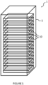
- FIG. 1 illustrates an example of a supercomputer 1 according to an embodiment of the invention.
- supercomputer 1 could be a server or any type of computer rack in which it is necessary to mount at least one liquid-cooled multiprocessor computing module.
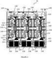
- FIG. 2 illustrates an example of a calculation blade 10 according to the invention.
- the computing blade 10 firstly comprises a motherboard 110 and a cold plate 120.
- the cold plate 120 is sized to cover the processor support and includes a plurality of heat sinks 122, a cooling circuit 124, an exhaust circuit 126, a so-called “cold” input connector 128 and a so-called “hot” output connector 129.
- the cooling circuit 124 comprises channels inside which circulates a so-called “cold” heat transfer fluid, entering the cooling circuit 124 via the cold inlet connector 128 and which is intended to supply the heat sinks 122.
- Each heat sink 122 is mounted opposite a processor to cool it by heat exchange.
- the evacuation circuit 126 comprises channels inside which circulates a so-called “hot” heat transfer fluid having heated up through the heat sinks 122 and which is evacuated through the hot outlet connector 129.
- Each network card 130 comprises a plug-in end 132 configured to receive a connector and is configured to enable data communication between the processor with which said network card 130 is associated and another processor of the computing blade 10 or of another computing blade 10 (of the supercomputer 1 or of another supercomputer) via said plug-in end 132.
- Each network card 130 is mounted on the cold plate 120 while being connected to the motherboard 110 via a connection system 140.
- the connection system 140 comprises a first connector 142, a second connector 144 and a cable (or a cable harness) 146 electrically connecting the first connector 142 and the second connector 144.
- the first connector 142 is connected to the plug-in end 132 of the network card 130.
- the second connector 144 is connected on the one hand to the first connector 142 via the cable 146 and on the other hand to the motherboard 110.
- the second connector 144 is connected to the motherboard 110 through the cold plate 120 in order to access the motherboard 110 by a short path and thus optimize the space occupied by the computing blade 10 and its components.
- the cable 146 is flexible so as to be able to conform to the space formed between the heat sinks 122 and to the connection direction of both the first connector 142 (here parallel to the plane along which the cold plate 120 extends) and the second connector 144 (here orthogonal to the plane along which the cold plate 120 extends).
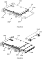
- Each network card 130 is mounted on the cold plate 120 via a support piece 150, as illustrated in the Figure 3 .
- the support part 150 comprises a body 152 and a holding device 154 mounted on said body 152 and configured to hold the first connector 142 when said first connector 142 is connected to the plug-in end 132 in order to prevent the first connector 142 from moving during transport or use of the computing blade 10.
- the holding device 154 makes it possible to hold the connector in the connected position on the plug-in end 132 in an optimized manner.
- the holding device 154 comprises a support blade 154L and a holding plate 154P.
- the support blade 154L receives the first connector 142 while the holding plate 154P blocks the first connector 142 on said support blade 154L.
- the support blade 154L is made of metal, preferably aluminum to conduct thermal energy. More preferably, the holding plate 154P is also made of metal, preferably steel.
- the support blade 154L is fixed to the body 152 of the support part 150 and extends parallel to the cold plate 120 while being offset by a distance relative to said cold plate 120.
- the body 152 of the support part 150 is made of a thermal energy conducting material, for example aluminum, in order to allow the cooling of the network card 130 by the thermal energy provided by the heat transfer fluid circulating in the cold plate 120.
- each network card 130 is fixed on an edge of the computing blade 10 by its fixing end, opposite the plug-in end 132.
- a metal fixing element 160 makes it possible to fix the network card 130 on the edge of the computing blade 10, for example by screwing or locking.
- the invention makes it possible to optimize the distribution of the components on either side of the cold plate 120, in particular to place the network cards 130 in the most suitable location, in particular on the opposite face of the cold plate 120 relative to the motherboard 110.
- the invention therefore makes it possible to obtain a computing blade 10 that is compact and easy to maintain.
- different types and models of network card can be used since they are no longer constrained by the position of the motherboard in a card-to-card insertion configuration.
Landscapes
- Engineering & Computer Science (AREA)
- Microelectronics & Electronic Packaging (AREA)
- Physics & Mathematics (AREA)
- General Engineering & Computer Science (AREA)
- Theoretical Computer Science (AREA)
- Computer Hardware Design (AREA)
- Thermal Sciences (AREA)
- Human Computer Interaction (AREA)
- General Physics & Mathematics (AREA)
- Power Engineering (AREA)
- Cooling Or The Like Of Electrical Apparatus (AREA)
Claims (15)
- Rechen-Blade (10) für einen Multi-Blade-Supercomputer (1), das Rechen-Blade (10) umfassend eine Hauptplatine (110), die eine Vielzahl von Prozessoren aufweist, die auf einem Träger montiert sind, und eine Kühlplatte (120), die zum Bedecken des Trägers der Prozessoren konfiguriert ist und umfassend eine Vielzahl von Kühlkörpern (122), einen Kühlkreislauf (124), der Kanäle aufweist, in denen ein sogenanntes "kaltes" Wärmeübertragungsfluid zirkuliert, das dazu bestimmt ist, die Kühlkörper (122) zu versorgen, und einen Ableitungskreislauf (126), der Kanäle aufweist, in denen ein sogenanntes "heißes" Wärmeübertragungsfluid zirkuliert, das sich durch die Kühlkörper (122) erwärmt hat, wobei jeder Kühlkörper (122) in Reihe mit einem Prozessor montiert ist, um ihn durch Wärmeaustausch zu kühlen, der Rechen-Blade (10) umfassend so viele Netzwerkkarten (130) wie Prozessoren, wobei jede Netzwerkkarte (130) einem Prozessor zugeordnet ist, jede Netzwerkkarte (130) umfassend ein Einsteckende (132), das zum Aufnehmen eines Verbinders (142) konfiguriert ist, wobei jede Netzwerkkarte (130) zum Ermöglichen einer Datenkommunikation zwischen dem Prozessor und einem anderen Prozessor konfiguriert ist, wobei das Rechen-Blade (10) dadurch gekennzeichnet ist, dass jede Netzwerkkarte (130) auf der Kühlplatte (120) montiert ist, wobei sie über ein Verbindungssystem (140) mit der Hauptplatine (110) verbunden ist, das System (140) umfassend einen ersten Verbinder (142), der mit dem Einsteckende (132) der Netzwerkkarte (130) verbunden ist, und einen zweiten Verbinder (144), der einerseits über ein Kabel (146) mit dem ersten Verbinder (142) und andererseits mit der Hauptplatine (110) verbunden ist.
- Rechen-Blade (10) nach Anspruch 1, wobei der zweite Verbinder (144) über die Kühlplatte (120) an die Hauptplatine (110) angeschlossen ist.
- Rechen-Blade (10) nach einem der vorstehenden Ansprüche, wobei jede Netzwerkkarte (130) über ein Trägerstück (150) an der Kühlplatte (120) montiert ist.
- Rechen-Blade (10) nach dem vorstehenden Anspruch, wobei das Trägerstück (150) einen Körper (152) und eine Haltevorrichtung (154) des ersten Verbinders (142) umfasst, die an dem Körper (152) montiert ist.
- Rechen-Blade (10) nach dem vorstehenden Anspruch, wobei die Haltevorrichtung (154) ein Träger-Blade (154L) des ersten Verbinders (142) und eine Halteplatte (154P) des ersten Verbinders (142) auf dem Träger-Blade (154L) umfasst.
- Rechen-Blade (10) nach dem vorstehenden Anspruch, wobei das Träger-Blade (154L) aus Metall, vorzugsweise Aluminium, hergestellt ist.
- Rechen-Blade (10) nach einem der Ansprüche 5 oder 6, wobei die Halteplatte (154P) aus Metall, vorzugsweise Stahl, hergestellt ist.
- Rechen-Blade (10) nach einem der Ansprüche 5 bis 7, wobei die Halteplatte (154P) mithilfe von mindestens einer Schraube (156), vorzugsweise mithilfe von zwei Schrauben (156), an dem Träger-Blade (154L) befestigt ist.
- Rechen-Blade (10) nach dem vorstehenden Anspruch, wobei die mindestens eine Schraube (156) verliergesichert oder unverlierbar ist und an der Halteplatte (154P) montiert ist.
- Rechen-Blade (10) nach einem der Ansprüche 5 bis 9, wobei das Träger-Blade (154L) an dem Körper (152) des Trägerstücks (150) befestigt ist, wobei es um einen Abstand relativ zu der Kühlplatte (120) versetzt ist.
- Rechen-Blade (10) nach einem der Ansprüche 3 bis 10, wobei der Körper (152) des Trägerstücks (150) aus einem Wärmeenergieleitermaterial hergestellt ist.
- Rechen-Blade (10) nach dem vorstehenden Anspruch, wobei der Körper (152) des Trägerstücks (150) aus Aluminium hergestellt ist.
- Rechen-Blade (10) nach einem der vorstehenden Ansprüche, wobei das Kabel (146) des Verbindungssystems (140) flexibel ist.
- Rechen-Blade (10) nach einem der vorstehenden Ansprüche, wobei jede Netzwerkkarte (130) an einer Kante des Rechen-Blades (10) durch ein Befestigungsende befestigt ist, das dem Steckende (132) gegenüberliegt.
- Supercomputer (1), umfassend mindestens ein Rechen-Blade (10) nach einem der vorstehenden Ansprüche.
Priority Applications (2)
| Application Number | Priority Date | Filing Date | Title |
|---|---|---|---|
| EP22306290.2A EP4332728B1 (de) | 2022-08-31 | 2022-08-31 | Computerblade mit versetzten netzwerkkarten |
| US18/364,768 US12309958B2 (en) | 2022-08-31 | 2023-08-03 | Offset network card computing blade |
Applications Claiming Priority (1)
| Application Number | Priority Date | Filing Date | Title |
|---|---|---|---|
| EP22306290.2A EP4332728B1 (de) | 2022-08-31 | 2022-08-31 | Computerblade mit versetzten netzwerkkarten |
Publications (2)
| Publication Number | Publication Date |
|---|---|
| EP4332728A1 EP4332728A1 (de) | 2024-03-06 |
| EP4332728B1 true EP4332728B1 (de) | 2025-07-09 |
Family
ID=84044157
Family Applications (1)
| Application Number | Title | Priority Date | Filing Date |
|---|---|---|---|
| EP22306290.2A Active EP4332728B1 (de) | 2022-08-31 | 2022-08-31 | Computerblade mit versetzten netzwerkkarten |
Country Status (2)
| Country | Link |
|---|---|
| US (1) | US12309958B2 (de) |
| EP (1) | EP4332728B1 (de) |
Families Citing this family (1)
| Publication number | Priority date | Publication date | Assignee | Title |
|---|---|---|---|---|
| US20250275100A1 (en) * | 2024-02-26 | 2025-08-28 | Zt Group Int'l, Inc. Dba Zt Systems | Computing system with external disconnects |
Family Cites Families (7)
| Publication number | Priority date | Publication date | Assignee | Title |
|---|---|---|---|---|
| US10459499B2 (en) * | 2017-05-26 | 2019-10-29 | Dell Products L.P. | Systems and methods for management of liquid cooling upgrades with liquid cooling adapter card |
| FR3075560B1 (fr) * | 2017-12-15 | 2020-10-16 | Bull Sas | Systeme de refroidissement liquide pour carte electronique constituee d'une plaque froide et de dissipateurs thermiques relies en liaisons souples avec ladite plaque froide |
| US10485143B2 (en) * | 2018-03-10 | 2019-11-19 | Baidu Usa Llc | Cold plate assembly for server liquid cooling of electronic racks of a data center |
| US10782749B2 (en) * | 2018-10-10 | 2020-09-22 | Hewlett Packard Enterprise Development Lp | Compute assembly for high speed ultra dense compute blades |
| US10905030B1 (en) * | 2019-07-24 | 2021-01-26 | Facebook, Inc. | Liquid-cooling within an air-cooled facility |
| US11409686B1 (en) * | 2021-01-21 | 2022-08-09 | Dell Products L.P. | Systems and methods for floating paddle card enablement |
| US11832417B2 (en) * | 2021-05-21 | 2023-11-28 | Quanta Computer Inc. | Support bracket for liquid cooling cold plate mechanism |
-
2022
- 2022-08-31 EP EP22306290.2A patent/EP4332728B1/de active Active
-
2023
- 2023-08-03 US US18/364,768 patent/US12309958B2/en active Active
Also Published As
| Publication number | Publication date |
|---|---|
| US20240074081A1 (en) | 2024-02-29 |
| EP4332728A1 (de) | 2024-03-06 |
| US12309958B2 (en) | 2025-05-20 |
Similar Documents
| Publication | Publication Date | Title |
|---|---|---|
| EP3368959B1 (de) | Rechnersystem mit gekühlter elektrischer stromversorgungseinheit | |
| US20150212555A1 (en) | Orthogonally hinged individualized memory module cooling | |
| US7599184B2 (en) | Liquid cooling loops for server applications | |
| US7641101B2 (en) | Method of assembling a cooling system for a multi-component electronics system | |
| US8077463B2 (en) | Heat dissipating system | |
| US7405936B1 (en) | Hybrid cooling system for a multi-component electronics system | |
| US7808780B2 (en) | Variable flow computer cooling system for a data center and method of operation | |
| JP2025128108A (ja) | 電子デバイスを冷却するためのコールドプレートおよびシステム | |
| EP2770810A1 (de) | Elektronische Karte, die mit einem Flüssigkeitskühlsystem versehen ist | |
| US20070291452A1 (en) | Heat Transfer Systems for Dissipating Thermal Loads From a Computer Rack | |
| EP2653021B1 (de) | Kühlung einer elektronischen vorrichtung | |
| US20210084793A1 (en) | Cooling chassis design for server liquid cooling of electronic racks of a data center | |
| EP4332728B1 (de) | Computerblade mit versetzten netzwerkkarten | |
| EP2420117A1 (de) | Gehäuse für eine onboard-elektronikkarte | |
| EP1142460B1 (de) | Elektronische baugruppe mit kühlelementen für elektronische bauelemente | |
| US12089366B2 (en) | Server and cooling system for enhanced immersion cooling | |
| EP3216331A1 (de) | Avionikraum | |
| US6538884B1 (en) | Method and apparatus for removing heat from a component | |
| EP3712744B1 (de) | Kühlkörper für mehrere speicher-arrays | |
| EP4345577A1 (de) | Kühlkörper für eine berechnungsblatt-array-karte | |
| US20080043442A1 (en) | Computer system with thermal conduction | |
| US7554808B2 (en) | Heat sink with thermoelectric module | |
| FR3139510A1 (fr) | Dispositif électronique de commande d’un radiateur électrique. | |
| EP4333575A1 (de) | Eingangskühlkörper für ein kühlsystem einer elektronischen superrechnerkarte | |
| US20250338432A1 (en) | Rotating cold plate assembly, system and method of operating cold plate assembly |
Legal Events
| Date | Code | Title | Description |
|---|---|---|---|
| PUAI | Public reference made under article 153(3) epc to a published international application that has entered the european phase |
Free format text: ORIGINAL CODE: 0009012 |
|
| STAA | Information on the status of an ep patent application or granted ep patent |
Free format text: STATUS: THE APPLICATION HAS BEEN PUBLISHED |
|
| AK | Designated contracting states |
Kind code of ref document: A1 Designated state(s): AL AT BE BG CH CY CZ DE DK EE ES FI FR GB GR HR HU IE IS IT LI LT LU LV MC MK MT NL NO PL PT RO RS SE SI SK SM TR |
|
| STAA | Information on the status of an ep patent application or granted ep patent |
Free format text: STATUS: REQUEST FOR EXAMINATION WAS MADE |
|
| 17P | Request for examination filed |
Effective date: 20240318 |
|
| RBV | Designated contracting states (corrected) |
Designated state(s): AL AT BE BG CH CY CZ DE DK EE ES FI FR GB GR HR HU IE IS IT LI LT LU LV MC MK MT NL NO PL PT RO RS SE SI SK SM TR |
|
| RAP1 | Party data changed (applicant data changed or rights of an application transferred) |
Owner name: LE COMMISSARIAT A L'ENERGIE ATOMIQUE ET AUX ENERGIES ALTERNATIVES Owner name: BULL SAS |
|
| RAP3 | Party data changed (applicant data changed or rights of an application transferred) |
Owner name: COMMISSARIAT A L'ENERGIE ATOMIQUE ET AUX ENERGIESALTERNATIVES Owner name: BULL SAS |
|
| GRAP | Despatch of communication of intention to grant a patent |
Free format text: ORIGINAL CODE: EPIDOSNIGR1 |
|
| STAA | Information on the status of an ep patent application or granted ep patent |
Free format text: STATUS: GRANT OF PATENT IS INTENDED |
|
| RIC1 | Information provided on ipc code assigned before grant |
Ipc: H05K 7/20 20060101ALI20250121BHEP Ipc: G06F 1/18 20060101ALI20250121BHEP Ipc: G06F 1/20 20060101AFI20250121BHEP |
|
| INTG | Intention to grant announced |
Effective date: 20250203 |
|
| GRAS | Grant fee paid |
Free format text: ORIGINAL CODE: EPIDOSNIGR3 |
|
| GRAA | (expected) grant |
Free format text: ORIGINAL CODE: 0009210 |
|
| STAA | Information on the status of an ep patent application or granted ep patent |
Free format text: STATUS: THE PATENT HAS BEEN GRANTED |
|
| P01 | Opt-out of the competence of the unified patent court (upc) registered |
Free format text: CASE NUMBER: APP_22890/2025 Effective date: 20250514 |
|
| AK | Designated contracting states |
Kind code of ref document: B1 Designated state(s): AL AT BE BG CH CY CZ DE DK EE ES FI FR GB GR HR HU IE IS IT LI LT LU LV MC MK MT NL NO PL PT RO RS SE SI SK SM TR |
|
| REG | Reference to a national code |
Ref country code: GB Ref legal event code: FG4D Free format text: NOT ENGLISH |
|
| REG | Reference to a national code |
Ref country code: CH Ref legal event code: EP |
|
| REG | Reference to a national code |
Ref country code: IE Ref legal event code: FG4D Free format text: LANGUAGE OF EP DOCUMENT: FRENCH |
|
| REG | Reference to a national code |
Ref country code: DE Ref legal event code: R096 Ref document number: 602022017277 Country of ref document: DE |
|
| PGFP | Annual fee paid to national office [announced via postgrant information from national office to epo] |
Ref country code: DE Payment date: 20250826 Year of fee payment: 4 |
|
| PGFP | Annual fee paid to national office [announced via postgrant information from national office to epo] |
Ref country code: FR Payment date: 20250902 Year of fee payment: 4 |
|
| REG | Reference to a national code |
Ref country code: NL Ref legal event code: MP Effective date: 20250709 |
|
| PG25 | Lapsed in a contracting state [announced via postgrant information from national office to epo] |
Ref country code: PT Free format text: LAPSE BECAUSE OF FAILURE TO SUBMIT A TRANSLATION OF THE DESCRIPTION OR TO PAY THE FEE WITHIN THE PRESCRIBED TIME-LIMIT Effective date: 20251110 |
|
| PG25 | Lapsed in a contracting state [announced via postgrant information from national office to epo] |
Ref country code: NL Free format text: LAPSE BECAUSE OF FAILURE TO SUBMIT A TRANSLATION OF THE DESCRIPTION OR TO PAY THE FEE WITHIN THE PRESCRIBED TIME-LIMIT Effective date: 20250709 |
|
| REG | Reference to a national code |
Ref country code: AT Ref legal event code: MK05 Ref document number: 1812420 Country of ref document: AT Kind code of ref document: T Effective date: 20250709 |
|
| PG25 | Lapsed in a contracting state [announced via postgrant information from national office to epo] |
Ref country code: IS Free format text: LAPSE BECAUSE OF FAILURE TO SUBMIT A TRANSLATION OF THE DESCRIPTION OR TO PAY THE FEE WITHIN THE PRESCRIBED TIME-LIMIT Effective date: 20251109 |
|
| PG25 | Lapsed in a contracting state [announced via postgrant information from national office to epo] |
Ref country code: NO Free format text: LAPSE BECAUSE OF FAILURE TO SUBMIT A TRANSLATION OF THE DESCRIPTION OR TO PAY THE FEE WITHIN THE PRESCRIBED TIME-LIMIT Effective date: 20251009 |
|
| REG | Reference to a national code |
Ref country code: LT Ref legal event code: MG9D |
|
| PG25 | Lapsed in a contracting state [announced via postgrant information from national office to epo] |
Ref country code: AT Free format text: LAPSE BECAUSE OF FAILURE TO SUBMIT A TRANSLATION OF THE DESCRIPTION OR TO PAY THE FEE WITHIN THE PRESCRIBED TIME-LIMIT Effective date: 20250709 |
|
| PG25 | Lapsed in a contracting state [announced via postgrant information from national office to epo] |
Ref country code: FI Free format text: LAPSE BECAUSE OF FAILURE TO SUBMIT A TRANSLATION OF THE DESCRIPTION OR TO PAY THE FEE WITHIN THE PRESCRIBED TIME-LIMIT Effective date: 20250709 |
|
| PG25 | Lapsed in a contracting state [announced via postgrant information from national office to epo] |
Ref country code: HR Free format text: LAPSE BECAUSE OF FAILURE TO SUBMIT A TRANSLATION OF THE DESCRIPTION OR TO PAY THE FEE WITHIN THE PRESCRIBED TIME-LIMIT Effective date: 20250709 |
|
| PG25 | Lapsed in a contracting state [announced via postgrant information from national office to epo] |
Ref country code: GR Free format text: LAPSE BECAUSE OF FAILURE TO SUBMIT A TRANSLATION OF THE DESCRIPTION OR TO PAY THE FEE WITHIN THE PRESCRIBED TIME-LIMIT Effective date: 20251010 |
|
| PG25 | Lapsed in a contracting state [announced via postgrant information from national office to epo] |
Ref country code: SE Free format text: LAPSE BECAUSE OF FAILURE TO SUBMIT A TRANSLATION OF THE DESCRIPTION OR TO PAY THE FEE WITHIN THE PRESCRIBED TIME-LIMIT Effective date: 20250709 |
|
| PG25 | Lapsed in a contracting state [announced via postgrant information from national office to epo] |
Ref country code: LV Free format text: LAPSE BECAUSE OF FAILURE TO SUBMIT A TRANSLATION OF THE DESCRIPTION OR TO PAY THE FEE WITHIN THE PRESCRIBED TIME-LIMIT Effective date: 20250709 |
|
| PG25 | Lapsed in a contracting state [announced via postgrant information from national office to epo] |
Ref country code: PL Free format text: LAPSE BECAUSE OF FAILURE TO SUBMIT A TRANSLATION OF THE DESCRIPTION OR TO PAY THE FEE WITHIN THE PRESCRIBED TIME-LIMIT Effective date: 20250709 Ref country code: BG Free format text: LAPSE BECAUSE OF FAILURE TO SUBMIT A TRANSLATION OF THE DESCRIPTION OR TO PAY THE FEE WITHIN THE PRESCRIBED TIME-LIMIT Effective date: 20250709 |
|
| PG25 | Lapsed in a contracting state [announced via postgrant information from national office to epo] |
Ref country code: RS Free format text: LAPSE BECAUSE OF FAILURE TO SUBMIT A TRANSLATION OF THE DESCRIPTION OR TO PAY THE FEE WITHIN THE PRESCRIBED TIME-LIMIT Effective date: 20251009 |
|
| PG25 | Lapsed in a contracting state [announced via postgrant information from national office to epo] |
Ref country code: ES Free format text: LAPSE BECAUSE OF FAILURE TO SUBMIT A TRANSLATION OF THE DESCRIPTION OR TO PAY THE FEE WITHIN THE PRESCRIBED TIME-LIMIT Effective date: 20250709 |
|
| PG25 | Lapsed in a contracting state [announced via postgrant information from national office to epo] |
Ref country code: RO Free format text: LAPSE BECAUSE OF FAILURE TO SUBMIT A TRANSLATION OF THE DESCRIPTION OR TO PAY THE FEE WITHIN THE PRESCRIBED TIME-LIMIT Effective date: 20250709 |
|
| REG | Reference to a national code |
Ref country code: CH Ref legal event code: H13 Free format text: ST27 STATUS EVENT CODE: U-0-0-H10-H13 (AS PROVIDED BY THE NATIONAL OFFICE) Effective date: 20260324 |
|
| PG25 | Lapsed in a contracting state [announced via postgrant information from national office to epo] |
Ref country code: SM Free format text: LAPSE BECAUSE OF FAILURE TO SUBMIT A TRANSLATION OF THE DESCRIPTION OR TO PAY THE FEE WITHIN THE PRESCRIBED TIME-LIMIT Effective date: 20250709 |
|
| PG25 | Lapsed in a contracting state [announced via postgrant information from national office to epo] |
Ref country code: DK Free format text: LAPSE BECAUSE OF FAILURE TO SUBMIT A TRANSLATION OF THE DESCRIPTION OR TO PAY THE FEE WITHIN THE PRESCRIBED TIME-LIMIT Effective date: 20250709 |
|
| PG25 | Lapsed in a contracting state [announced via postgrant information from national office to epo] |
Ref country code: LU Free format text: LAPSE BECAUSE OF NON-PAYMENT OF DUE FEES Effective date: 20250831 Ref country code: IT Free format text: LAPSE BECAUSE OF FAILURE TO SUBMIT A TRANSLATION OF THE DESCRIPTION OR TO PAY THE FEE WITHIN THE PRESCRIBED TIME-LIMIT Effective date: 20250709 |
|
| PG25 | Lapsed in a contracting state [announced via postgrant information from national office to epo] |
Ref country code: CZ Free format text: LAPSE BECAUSE OF FAILURE TO SUBMIT A TRANSLATION OF THE DESCRIPTION OR TO PAY THE FEE WITHIN THE PRESCRIBED TIME-LIMIT Effective date: 20250709 Ref country code: CH Free format text: LAPSE BECAUSE OF NON-PAYMENT OF DUE FEES Effective date: 20250831 |
|
| PG25 | Lapsed in a contracting state [announced via postgrant information from national office to epo] |
Ref country code: SK Free format text: LAPSE BECAUSE OF FAILURE TO SUBMIT A TRANSLATION OF THE DESCRIPTION OR TO PAY THE FEE WITHIN THE PRESCRIBED TIME-LIMIT Effective date: 20250709 Ref country code: EE Free format text: LAPSE BECAUSE OF FAILURE TO SUBMIT A TRANSLATION OF THE DESCRIPTION OR TO PAY THE FEE WITHIN THE PRESCRIBED TIME-LIMIT Effective date: 20250709 |