EP4332806B1 - Contrôleur d'automatisation et procédé de fonctionnement d'un contrôleur d'automatisation - Google Patents
Contrôleur d'automatisation et procédé de fonctionnement d'un contrôleur d'automatisation Download PDFInfo
- Publication number
- EP4332806B1 EP4332806B1 EP22192580.3A EP22192580A EP4332806B1 EP 4332806 B1 EP4332806 B1 EP 4332806B1 EP 22192580 A EP22192580 A EP 22192580A EP 4332806 B1 EP4332806 B1 EP 4332806B1
- Authority
- EP
- European Patent Office
- Prior art keywords
- hwif2
- hwif1
- register
- value
- network
- Prior art date
- Legal status (The legal status is an assumption and is not a legal conclusion. Google has not performed a legal analysis and makes no representation as to the accuracy of the status listed.)
- Active
Links
Images


Classifications
-
- G—PHYSICS
- G05—CONTROLLING; REGULATING
- G05B—CONTROL OR REGULATING SYSTEMS IN GENERAL; FUNCTIONAL ELEMENTS OF SUCH SYSTEMS; MONITORING OR TESTING ARRANGEMENTS FOR SUCH SYSTEMS OR ELEMENTS
- G05B19/00—Program-control systems
- G05B19/02—Program-control systems electric
- G05B19/04—Program control other than numerical control, i.e. in sequence controllers or logic controllers
- G05B19/048—Monitoring; Safety
-
- G—PHYSICS
- G06—COMPUTING OR CALCULATING; COUNTING
- G06F—ELECTRIC DIGITAL DATA PROCESSING
- G06F21/00—Security arrangements for protecting computers, components thereof, programs or data against unauthorised activity
- G06F21/50—Monitoring users, programs or devices to maintain the integrity of platforms, e.g. of processors, firmware or operating systems
- G06F21/57—Certifying or maintaining trusted computer platforms, e.g. secure boots or power-downs, version controls, system software checks, secure updates or assessing vulnerabilities
-
- G—PHYSICS
- G05—CONTROLLING; REGULATING
- G05B—CONTROL OR REGULATING SYSTEMS IN GENERAL; FUNCTIONAL ELEMENTS OF SUCH SYSTEMS; MONITORING OR TESTING ARRANGEMENTS FOR SUCH SYSTEMS OR ELEMENTS
- G05B15/00—Systems controlled by a computer
- G05B15/02—Systems controlled by a computer electric
-
- H—ELECTRICITY
- H04—ELECTRIC COMMUNICATION TECHNIQUE
- H04L—TRANSMISSION OF DIGITAL INFORMATION, e.g. TELEGRAPHIC COMMUNICATION
- H04L63/00—Network architectures or network communication protocols for network security
- H04L63/02—Network architectures or network communication protocols for network security for separating internal from external traffic, e.g. firewalls
-
- H—ELECTRICITY
- H04—ELECTRIC COMMUNICATION TECHNIQUE
- H04L—TRANSMISSION OF DIGITAL INFORMATION, e.g. TELEGRAPHIC COMMUNICATION
- H04L63/00—Network architectures or network communication protocols for network security
- H04L63/08—Network architectures or network communication protocols for network security for authentication of entities
-
- H—ELECTRICITY
- H04—ELECTRIC COMMUNICATION TECHNIQUE
- H04L—TRANSMISSION OF DIGITAL INFORMATION, e.g. TELEGRAPHIC COMMUNICATION
- H04L67/00—Network arrangements or protocols for supporting network services or applications
- H04L67/01—Protocols
- H04L67/12—Protocols specially adapted for proprietary or special-purpose networking environments, e.g. medical networks, sensor networks, networks in vehicles or remote metering networks
-
- H—ELECTRICITY
- H04—ELECTRIC COMMUNICATION TECHNIQUE
- H04L—TRANSMISSION OF DIGITAL INFORMATION, e.g. TELEGRAPHIC COMMUNICATION
- H04L9/00—Cryptographic mechanisms or cryptographic arrangements for secret or secure communications; Network security protocols
- H04L9/40—Network security protocols
Definitions
- the invention relates to an automation controller comprising a processor onto which an operating system is loaded, a first interface module with at least a first Ethernet channel and a second Ethernet channel, which are connected to a first selection circuit, a second interface module with at least a first Ethernet channel and a second Ethernet channel, which are connected to a second selection circuit, a first network interface for connection to a first network and a second network interface for connection to a second network, connecting means for connecting the selection circuits to the network interfaces, a first register with a first register value and a second register with a second register value, the selection circuits being designed to assign the Ethernet channels to the network interfaces in accordance with the register values.
- the task is solved in that the operating system is designed to generate a number in a definable cycle and that a query means is available which is designed to apply a logical function to the register values with the number in each cycle, whereby a return value is generated, the operating system is further designed to apply the logical function again to the return value with the number, whereby the register values are generated again, furthermore there are code instructions which are designed to compare the regenerated register values with test values and to put the automation controller into a safe state in the event of a deviation.
- a security-relevant value, in particular the register value, for the realization of a network separation is now secured by a double input (target value and a check value).
- the actual value is read out cyclically and compared with the test value. If there is a discrepancy, an appropriate reaction is made, e.g. stop state or defect with shutdown of all network interfaces.
- Reading the actual value of the register values could be achieved using the following mechanism.
- a channel to an EDDP Ethernet Device Driver PNIP
- the operating system of the automation controller could generate a 32-bit random value every 1,000 ms and pass it on to the EDDP.
- the 32 Bit random value is XORed with the actual values and returned to the operating system.
- These so-called actual port mapping values are then compared with the test values by the automation controller using special code instructions and if there is a deviation, the automation controller switches to a defect state, for example, and all physical ports/network interfaces are switched off.
- Another design variant of the automation controller provides a test value table with the test values and a combination table.
- the combination table lists the combinations of the assignments of the Ethernet channels to the network interfaces, with a test value assigned to the respective combination being stored in the test value table for each combination. Since known test values have now been assigned to the combinations, a set port mapping can be cyclically tested against an expectation.
- the testing is further improved if the automation controller has code instructions configured to multiply the first regenerated register value by a first factor and check whether the product corresponds to the first test value, and to multiply the second regenerated register value by a second factor and check whether the product corresponds to the second test value.
- the register values for the assignment of the Ethernet channels to the network interfaces are selected in such a way that is that the first network and the second network are separated from each other.
- register values Such a safety-relevant setting of the register values must be protected against falsification by hardware and software errors.
- This setting affects the "network isolator according to IEC 61784-3-3 (Profisafe)" function, which is provided by a fail-safe CPU (F-CPU).
- the protection can also be carried out effectively without a user program (F-program) or even in a stop state.
- a network separator is understood to be an absolute network separator between two network interfaces. If the first network interface and the second network interface belong to different local Ethernet interfaces or networks, no bridging may be implemented for these interfaces on communication level 2. If the first interface should lead to a local Ethernet network and the other to a backplane bus module of the automation controller with an Ethernet interface, no bridging may be implemented on communication level 2 for this configuration either.
- the automation controller has an input device that is designed so that a user can select and set the combinations. For example, a user could select the interface variants or combinations via a display on the automation controller. The user could confirm the selected combination by confirming the associated test value.
- the object mentioned at the outset is achieved by a method for operating an automation controller, wherein for network separation of a first network and a second network, a first register value of a first register and a second register value of a second register is monitored against falsification by hardware and software errors, the register values being used to set a first or second selection circuit, the selection circuits being operated according to the register values to assign Ethernet channels of interface modules to network interfaces and thus to the networks, a number being generated from an operating system of the automation controller in a definable cycle and a logical function being applied to the register values with the number with each cycle, thereby generating a return value, the logical function is then applied to the return value with the number in the operating system, thereby generating the register values again, and code instructions are also run through which compare the regenerated register values with test values and, in the event of a deviation, put the automation controller into a safe state.
- a check value table with check values and a combination table have proven to be helpful.
- the combination table combinations of the assignments of the Ethernet channels to the network interfaces are listed and used for comparison, whereby in the check value table a check value assigned to the respective combination is stored for each combination.
- the first regenerated register value is multiplied by a first factor and it is checked whether the product corresponds to the first check value
- the second regenerated register value is multiplied by a second factor and it is checked whether the product corresponds to the second check value.
- an automation controller is operated with regard to functional safety, it is advantageous if the automation controller is designed as a functional safety-oriented designed automation control and the network separation of the first network and the second network is carried out according to the IEC 61784-3 standard.
- the drawing shows an embodiment of the invention.
- the automation controller 1 has a processor MP on which an operating system FW is loaded.
- the automation controller 1 has a first interface module IF1 and a second interface module IF2.
- the first interface module IF1 is designed, for example, as a PN-IP 100 megabit/s module.
- the second interface module IF2 is designed as a PN-IP 100 gigabit/s module.
- Selection circuits Mux1, Mux2 are arranged between the interface modules IF1, IF2 and network interfaces P1,..., P4.
- the automation controller 1 has a first register 5041 with a first register value HWIF1 and a second register 5042 with a second register value HWIF2.
- the selection circuits Mux1,Mux2 are designed according to the register values HIF1,HIF2, the Ethernet channels E11,...,E22 and the network interfaces P1,P2,P3,P4. Since the assignment is safety-relevant, especially to the functionality of a network isolator in a Profisafe environment, the assigned register values HWIF1,HWIF2 must be monitored.
- the operating system FW is designed to generate a number ZZ, e.g. a random number, in a definable cycle Z and to apply a logical function to the register values HWIF1, HWIF2 with the number ZZ with each cycle Z via a query means AM, which is designed. This generates a return value ZZ' and returns it to the operating system FW.
- the logical function XOR is again applied to the returned return value ZZ' with the number ZZ, whereby the register values HHIF1 ⁇ , HWIF2 ⁇ are again generated.
- code instructions SC are available which are designed to compare the newly generated register values HWIF1', HWIF2' with test values CV_HWIF1, CV_HWIF2 (see FIG 3 ) and, in the event of a deviation, to put the automation controller 1 into a safe state.
- a comparison means 30 is available which forces the automation controller 1 into a stop state.
- the code instructions SC are further designed to multiply the first regenerated register value HWIF1' by a first factor F1 and to check whether the product corresponds to the first check value CV_HWIF1, and to multiply the second register value HWIF2' by a second factor F2 and to check whether the product corresponds to the second check value CV_HWIF2.
- the sixth combination K6 from the FIG 2 shown configuration table KT.
- the sixth combination K6 provides that the first Ethernet channel E11 of the first interface module IF1 is connected to the first network interface P1 and that the second Ethernet channel E12 of the second interface module IF2 is connected to the second network interface P2.
- the following register values result for the sixth combination K6.
- the first register value HWIF1 is given the value 0 ⁇ 7770 H and the second register value HWIF2 is given the value 0 ⁇ 71 H.
- the check values 0xEE E000 H and 0xE200 0000 H are selected for the first register value HWIF1 and the second register value HWIF2 for the sixth combination K6. This means that multiplying the register value 0 ⁇ 770 H by 0 ⁇ 200 H must result in the corresponding check value 0xEE E000 H.
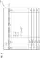
- the FIG 4 shows a possible assignment using the example of the first register 5041.
- the first register 5041 has the address 000504H. In a line with the designation bit number, 32 bits can be assigned to the register. As an example, the configuration 0 ⁇ 7770 H was assigned. This means that bits 0 to 2 are assigned 0, bits 4 to 6 are assigned 1, bits 8 to 10 are also assigned 1 and bits 12 to 14 are also assigned 1. Binary numbers can be divided into groups of four and easily converted into hexadecimal numbers, ie a block with four "1"s corresponds to a "7".
- bit numbers 0 to 2 shows that a configuration with "000” is equivalent to a connection to the first network interface P1, an assignment of bits "001” corresponds to a connection to the second network interface E2, an assignment of bits with “010” corresponds to a connection to the third network interface P3 and an assignment of bits with "011” corresponds to a connection to the fourth network interface P4.
- the assignment of bits with "100” to "110” is reserved and behaves like the assignment with "111", which is equivalent to no network interface assignment.
- all bits receive 0x7 H , which in turn corresponds to "111" and therefore does not represent a port assignment for security reasons.
Landscapes
- Engineering & Computer Science (AREA)
- Computer Security & Cryptography (AREA)
- General Engineering & Computer Science (AREA)
- Computer Networks & Wireless Communication (AREA)
- Signal Processing (AREA)
- Computer Hardware Design (AREA)
- General Physics & Mathematics (AREA)
- Physics & Mathematics (AREA)
- Computing Systems (AREA)
- Automation & Control Theory (AREA)
- Software Systems (AREA)
- Theoretical Computer Science (AREA)
- Medical Informatics (AREA)
- General Health & Medical Sciences (AREA)
- Health & Medical Sciences (AREA)
- Small-Scale Networks (AREA)
Claims (9)
- Unité (1) de commande d'automatisation comprenant- un processeur (MP), sur lequel un système (FW) de fonctionnement est chargé,- un premier module (IF1) d'interface ayant au moins un premier canal (E11) Ethernet et un deuxième canal (E12) Ethernet, qui sont raccordés à un premier circuit (Mux1) de sélection,- un deuxième module (IF2) d'interface ayant au moins un premier canal (EA21) d'Ethernet et un deuxième canal (EA22) d'Ethernet, qui sont raccordés à un deuxième circuit (Mux2) de sélection,- une première interface (P1) de réseau pour le raccordement à un premier réseau (N1) et une deuxième interface (P2) de réseau pour le raccordement à un deuxième réseau (N2),- des moyens (VM) de liaison conformés pour relier les circuits (Mux1, Mux2) de sélection aux interfaces (P1, P2) de réseau,- un premier registre (5041) ayant une première valeur (HWIF1) de registre et un deuxième registre (5042) ayant une deuxième valeur (HWIF2) de registre, les circuits (Mux1, Mux2) de sélection étant conformés conformément aux valeurs (HWIF1, HWIF2) de registre pour associer les canaux (E11,...,E22) d'Ethernet aux interfaces (P1, P2) de réseau,caractérisée en ce que le système (FW) de fonctionnement est conformé pour créer un nombre (ZZ) dans un cycle (Z) pouvant être déterminé et en ce qu'il y a un moyen (AM) d'interrogation, qui est conformé pour appliquer avec chaque cycle (Z) aux valeurs (HWIF1, HWIF2) de registre avec le nombre (ZZ) une fonction (XOR) logique, grâce à quoi il est produit une valeur (ZZ') de restitution, le système (FW) de fonctionnement est conformé en outre pour appliquer à la valeur (ZZ') de restitution avec le nombre (ZZ) la fonction (XOR) logique, grâce à quoi il est produit à nouveau les valeurs (HWIF1', HWIF2') de registre, il y a en outre des instructions (SC) de code, qui sont conformés pour comparer les valeurs (HWIF1', HWIF2') de registre produites à nouveau à des valeurs (CV_HWIF1, CV_HWIF2) de contrôle et s'il y a un écart pour mettre l'unité (1) de commande d'automatisation dans un état sécurisé.
- Unité de commande d'automatisation suivant la revendication 1, comportant une table (PWT) de valeurs de contrôle ayant les valeurs (CV_HWIF1, CV_HWIF2) de contrôle et une table (KT) de combinaison, dans laquelle des combinaisons (K1,...,K6) des associations des canaux (E11,...,E22) Ethernet aux interfaces (P1, P2) de réseau sont énumérées, dans lequel dans le tableau (PWT) de valeurs de contrôle est mise en mémoire pour chaque combinaison (K1,...,K6) une valeur (CV_HWIF1, CV_HWIF2) de contrôle associée à la combinaison respective.
- Unité (1) de commande d'automatisation suivant la revendication 2, dans lequel les instructions (SC) de code sont conformées pour multiplier la première valeur (HWIF1') de registre produite à nouveau par un premier facteur (F1) et pour contrôler si le produit correspond à la première valeur (CV_HWIF1) de contrôle, et pour multiplier la deuxième valeur (HWIF2') de registre produite à nouveau par un deuxième facteur (F2) et pour contrôler si le produit correspond à la deuxième valeur (CV_HWIF2) de contrôle.
- Unité (1) de commande d'automatisation suivant l'une des revendications 1 à 3, dans laquelle les valeurs (HWIF1, HWIF2) de registre sont choisies pour l'association des canaux (E11,...,E22) Ethernet aux interfaces (P1, P2) de réseau, de manière à s'assurer que le premier réseau (N1) et le deuxième réseau (N2) soient séparés l'un de l'autre.
- Unité de commande d'automatisation suivant l'une des revendications 2 à 4, dans lequel il y a un moyen (EM) d'entrée, qui est conformé de manière à ce qu'un utilisateur puisse sélectionner et choisir les combinaisons (K1,...,K6).
- Procédé pour faire fonctionner une unité (1) de commande d'automatisation, dans lequel pour séparer un premier réseau (N1) d'un deuxième réseau (N2), on contrôle, en ce qui concerne des altérations par défaut de matériel et de logiciel, une première valeur (HWIF1) d'un premier registre (5041) et une deuxième valeur (HWIF2) de registre d'un deuxième registre (5042), dans lequel on utilise les valeurs (HWIF1, HWIF2) de registre pour le réglage d'un premier et respectivement d'un deuxième circuit (Mux1, Mux2) de sélection, les circuits (Mux1, Mux2) de sélection fonctionnant ainsi de manière à associer, conformément aux valeurs (HWIF1, HWIF2) de registre des canaux (E11,...,E22) Ethernet de modules (IF1, IF2) d'interface à des interfaces (P1, P2) de réseau et ainsi aux réseaux (NW1, NW2), dans lequel à partir d'un système (FW) de fonctionnement de l'unité (1) de commande d'automatisation, on crée dans un cycle (Z) pouvant être déterminé un nombre (ZZ) et avec chaque cycle (Z) on applique aux valeurs (HWIF1, HWIF2) de registre avec le nombre (Z) une fonction (XOR) logique, grâce à quoi il est produit une valeur (Z') de restitution, on applique dans le système (FW) de fonctionnement à nouveau à la valeur (Z') de restitution avec le nombre (ZZ) la fonction (XOR) logique, grâce à quoi on produit à nouveau les valeurs (HWIF1', HWIF2') de registre, on effectue en outre des instructions (SC) de code, qui comparent les valeurs (HWIF1', HWIF2') de registre produites à nouveau à des valeurs (CV_HWIF1, CV_HWIF2) de contrôle et, s'il y a un écart, on met l'unité (1) de commande d'automatisation dans un état sécurisé.
- Procédé suivant la revendication 6, dans lequel on utilise une table (PWT) de valeurs de contrôle ayant les valeurs (CV_HWIF1, CV_HWIF2) de contrôle et une table (KT) de combinaisons, dans laquelle des combinaisons (K1,...,K6) des associations des canaux (E11, ..., E22) Ethernet aux interfaces (P1, P2) de réseau sont énumérées, dans lequel on met dans la table (PWT) de valeurs de contrôle, pour chaque combinaison (K1,...,K6), une valeur (CV_HWIF1, CV_HWIF2) de contrôle associée à la combinaison (K1,...,K6) respective.
- Procédé suivant la revendication 6 ou 7, dans lequel par les instructions (SC) de code, on multiplie la première valeur (HWIF1') de registre produite à nouveau par un premier facteur (F1) et on contrôle si le produit correspond à la première valeur (CV_HWIF1) de contrôle, et on multiplie la deuxième valeur (HWIF2') de registre produit à nouveau par un deuxième facteur (F2) et on contrôle si le produit correspond à la deuxième valeur (CV_HWIF2) de contrôle.
- Procédé suivant l'une des revendications 6 à 8, dans lequel on fait fonctionner l'unité (1) de commande d'automatisation comme une commande d'automatisation conçue en sécurité fonctionnelle et séparer le premier réseau (N1) du deuxième réseau (N2) s'effectue suivant la norme IEC 61784-3.
Priority Applications (3)
| Application Number | Priority Date | Filing Date | Title |
|---|---|---|---|
| EP22192580.3A EP4332806B1 (fr) | 2022-08-29 | 2022-08-29 | Contrôleur d'automatisation et procédé de fonctionnement d'un contrôleur d'automatisation |
| CN202311093659.1A CN117640131A (zh) | 2022-08-29 | 2023-08-28 | 自动化控制器和用于运行自动化控制器的方法 |
| US18/238,893 US12547134B2 (en) | 2022-08-29 | 2023-08-28 | Automation controller and method for operating the automation controller |
Applications Claiming Priority (1)
| Application Number | Priority Date | Filing Date | Title |
|---|---|---|---|
| EP22192580.3A EP4332806B1 (fr) | 2022-08-29 | 2022-08-29 | Contrôleur d'automatisation et procédé de fonctionnement d'un contrôleur d'automatisation |
Publications (3)
| Publication Number | Publication Date |
|---|---|
| EP4332806A1 EP4332806A1 (fr) | 2024-03-06 |
| EP4332806B1 true EP4332806B1 (fr) | 2024-12-25 |
| EP4332806C0 EP4332806C0 (fr) | 2024-12-25 |
Family
ID=83318891
Family Applications (1)
| Application Number | Title | Priority Date | Filing Date |
|---|---|---|---|
| EP22192580.3A Active EP4332806B1 (fr) | 2022-08-29 | 2022-08-29 | Contrôleur d'automatisation et procédé de fonctionnement d'un contrôleur d'automatisation |
Country Status (3)
| Country | Link |
|---|---|
| US (1) | US12547134B2 (fr) |
| EP (1) | EP4332806B1 (fr) |
| CN (1) | CN117640131A (fr) |
Family Cites Families (2)
| Publication number | Priority date | Publication date | Assignee | Title |
|---|---|---|---|---|
| DE102004028388A1 (de) * | 2004-06-14 | 2006-01-26 | Siemens Ag | Datenübertragungseinrichtung und Verfahren zur Datenübertragung mit verringertem Ausfallrisiko |
| EP3819804A1 (fr) * | 2019-11-08 | 2021-05-12 | Siemens Aktiengesellschaft | Vérification de l'intégrité d'un contenu de registre |
-
2022
- 2022-08-29 EP EP22192580.3A patent/EP4332806B1/fr active Active
-
2023
- 2023-08-28 CN CN202311093659.1A patent/CN117640131A/zh active Pending
- 2023-08-28 US US18/238,893 patent/US12547134B2/en active Active
Also Published As
| Publication number | Publication date |
|---|---|
| EP4332806A1 (fr) | 2024-03-06 |
| US20240069509A1 (en) | 2024-02-29 |
| CN117640131A (zh) | 2024-03-01 |
| EP4332806C0 (fr) | 2024-12-25 |
| US12547134B2 (en) | 2026-02-10 |
Similar Documents
| Publication | Publication Date | Title |
|---|---|---|
| EP0186724B1 (fr) | Dispositif de test et de diagnostic pour une calculatrice numérique | |
| DE102005063162A1 (de) | Verfahren zum Testen von Gerätebeschreibungen für Feldgeräte der Automatisierungstechnik | |
| WO2008040641A2 (fr) | Procédé et dispositif de gestion des pannes | |
| EP1149295B1 (fr) | Dispositif de commande pour commander des applications cruciales pour la securite | |
| EP1639465B1 (fr) | Procede permettant de surveiller l'execution d'un programme dans un micro-ordinateur | |
| DE102004004572A1 (de) | Fehlerdiagnoseverfahren für ein Fahrzeugkommunikationsnetz | |
| DE102022207044A1 (de) | Netzwerkvorrichtung- sicherheitsprotokoll | |
| EP2765465B1 (fr) | Module de communication à bus de terrain et son procédé de fonctionnement | |
| EP4332806B1 (fr) | Contrôleur d'automatisation et procédé de fonctionnement d'un contrôleur d'automatisation | |
| EP1251416B1 (fr) | Dispositif de diagnostic pour un dispositif de terrain avec transmission des informations de manière indépendante de la commande | |
| WO2022175026A1 (fr) | Véhicule à moteur doté d'une pluralité de dispositifs de commande qui fournissent différentes fonctions de véhicule dans le véhicule à moteur et procédé de configuration des dispositifs de commande et dispositif de commande | |
| DE102009033229B4 (de) | Verfahren zur Erkennung von Doppeladressierungen in AS Interface Netzen | |
| WO2002071223A1 (fr) | Systeme informatique tolerant aux pannes et procede d'utilisation d'un tel systeme | |
| DE102004043063B4 (de) | Verfahren zum Betreiben eines Halbleiter-Bauelements mit einem Test-Modul | |
| EP4046339B1 (fr) | Agencement d'essai sûr | |
| DE102006062604A1 (de) | Verfahren zum Testen von Gerätebeschreibungen für Feldgeräte der Automatisierungstechnik | |
| DE102021001276A1 (de) | Anbindung von Eingangs- und oder Ausgangsmodulen an einen Feldbus mit einer übergeordneten Steuerung | |
| DE102022202790B4 (de) | Verfahren, Prüfstandaufbau und Fahrzeug zum Durchführen eines Stabilitätstests einer eingebetteten Fahrzeugarchitektur | |
| DE69506764T2 (de) | Verfahren und Einrichtung zum Fehlernachweis auf elektronischen Platinen | |
| EP4066114A1 (fr) | Procédé de vérification d'une liaison de signaux | |
| DE102017128970A1 (de) | Vorrichtung und Verfahren zum Prüfen des spezifikationsgerechten Verhaltens von Steuergeräten | |
| EP1738262A1 (fr) | Procede et systeme de commande pour reconnaitre une erreur lors du traitement de donnees dans un systeme de traitement | |
| DE102016123332A1 (de) | Virtuelle Inbetriebnahme und Simulation eines Gebäudeautomatisierungssystems | |
| WO2026078108A1 (fr) | Unité de commande comprenant un composant logiciel de sécurité | |
| EP3002652B1 (fr) | Procédé de surveillance d'état dans un système d'automatisation industriel et programme de commande |
Legal Events
| Date | Code | Title | Description |
|---|---|---|---|
| PUAI | Public reference made under article 153(3) epc to a published international application that has entered the european phase |
Free format text: ORIGINAL CODE: 0009012 |
|
| STAA | Information on the status of an ep patent application or granted ep patent |
Free format text: STATUS: REQUEST FOR EXAMINATION WAS MADE |
|
| 17P | Request for examination filed |
Effective date: 20230210 |
|
| AK | Designated contracting states |
Kind code of ref document: A1 Designated state(s): AL AT BE BG CH CY CZ DE DK EE ES FI FR GB GR HR HU IE IS IT LI LT LU LV MC MK MT NL NO PL PT RO RS SE SI SK SM TR |
|
| GRAP | Despatch of communication of intention to grant a patent |
Free format text: ORIGINAL CODE: EPIDOSNIGR1 |
|
| STAA | Information on the status of an ep patent application or granted ep patent |
Free format text: STATUS: GRANT OF PATENT IS INTENDED |
|
| RIC1 | Information provided on ipc code assigned before grant |
Ipc: G06F 21/57 20130101AFI20240620BHEP |
|
| INTG | Intention to grant announced |
Effective date: 20240718 |
|
| GRAS | Grant fee paid |
Free format text: ORIGINAL CODE: EPIDOSNIGR3 |
|
| GRAA | (expected) grant |
Free format text: ORIGINAL CODE: 0009210 |
|
| STAA | Information on the status of an ep patent application or granted ep patent |
Free format text: STATUS: THE PATENT HAS BEEN GRANTED |
|
| AK | Designated contracting states |
Kind code of ref document: B1 Designated state(s): AL AT BE BG CH CY CZ DE DK EE ES FI FR GB GR HR HU IE IS IT LI LT LU LV MC MK MT NL NO PL PT RO RS SE SI SK SM TR |
|
| REG | Reference to a national code |
Ref country code: GB Ref legal event code: FG4D Free format text: NOT ENGLISH |
|
| REG | Reference to a national code |
Ref country code: CH Ref legal event code: EP |
|
| REG | Reference to a national code |
Ref country code: DE Ref legal event code: R096 Ref document number: 502022002495 Country of ref document: DE |
|
| REG | Reference to a national code |
Ref country code: IE Ref legal event code: FG4D Free format text: LANGUAGE OF EP DOCUMENT: GERMAN |
|
| U01 | Request for unitary effect filed |
Effective date: 20241225 |
|
| U07 | Unitary effect registered |
Designated state(s): AT BE BG DE DK EE FI FR IT LT LU LV MT NL PT RO SE SI Effective date: 20250108 |
|
| PG25 | Lapsed in a contracting state [announced via postgrant information from national office to epo] |
Ref country code: HR Free format text: LAPSE BECAUSE OF FAILURE TO SUBMIT A TRANSLATION OF THE DESCRIPTION OR TO PAY THE FEE WITHIN THE PRESCRIBED TIME-LIMIT Effective date: 20241225 |
|
| PG25 | Lapsed in a contracting state [announced via postgrant information from national office to epo] |
Ref country code: NO Free format text: LAPSE BECAUSE OF FAILURE TO SUBMIT A TRANSLATION OF THE DESCRIPTION OR TO PAY THE FEE WITHIN THE PRESCRIBED TIME-LIMIT Effective date: 20250325 |
|
| PG25 | Lapsed in a contracting state [announced via postgrant information from national office to epo] |
Ref country code: GR Free format text: LAPSE BECAUSE OF FAILURE TO SUBMIT A TRANSLATION OF THE DESCRIPTION OR TO PAY THE FEE WITHIN THE PRESCRIBED TIME-LIMIT Effective date: 20250326 |
|
| PG25 | Lapsed in a contracting state [announced via postgrant information from national office to epo] |
Ref country code: RS Free format text: LAPSE BECAUSE OF FAILURE TO SUBMIT A TRANSLATION OF THE DESCRIPTION OR TO PAY THE FEE WITHIN THE PRESCRIBED TIME-LIMIT Effective date: 20250325 |
|
| PG25 | Lapsed in a contracting state [announced via postgrant information from national office to epo] |
Ref country code: SM Free format text: LAPSE BECAUSE OF FAILURE TO SUBMIT A TRANSLATION OF THE DESCRIPTION OR TO PAY THE FEE WITHIN THE PRESCRIBED TIME-LIMIT Effective date: 20241225 |
|
| PG25 | Lapsed in a contracting state [announced via postgrant information from national office to epo] |
Ref country code: PL Free format text: LAPSE BECAUSE OF FAILURE TO SUBMIT A TRANSLATION OF THE DESCRIPTION OR TO PAY THE FEE WITHIN THE PRESCRIBED TIME-LIMIT Effective date: 20241225 |
|
| PG25 | Lapsed in a contracting state [announced via postgrant information from national office to epo] |
Ref country code: ES Free format text: LAPSE BECAUSE OF FAILURE TO SUBMIT A TRANSLATION OF THE DESCRIPTION OR TO PAY THE FEE WITHIN THE PRESCRIBED TIME-LIMIT Effective date: 20241225 |
|
| PG25 | Lapsed in a contracting state [announced via postgrant information from national office to epo] |
Ref country code: IS Free format text: LAPSE BECAUSE OF FAILURE TO SUBMIT A TRANSLATION OF THE DESCRIPTION OR TO PAY THE FEE WITHIN THE PRESCRIBED TIME-LIMIT Effective date: 20250425 |
|
| PG25 | Lapsed in a contracting state [announced via postgrant information from national office to epo] |
Ref country code: SK Free format text: LAPSE BECAUSE OF FAILURE TO SUBMIT A TRANSLATION OF THE DESCRIPTION OR TO PAY THE FEE WITHIN THE PRESCRIBED TIME-LIMIT Effective date: 20241225 |
|
| PG25 | Lapsed in a contracting state [announced via postgrant information from national office to epo] |
Ref country code: CZ Free format text: LAPSE BECAUSE OF FAILURE TO SUBMIT A TRANSLATION OF THE DESCRIPTION OR TO PAY THE FEE WITHIN THE PRESCRIBED TIME-LIMIT Effective date: 20241225 |
|
| U20 | Renewal fee for the european patent with unitary effect paid |
Year of fee payment: 4 Effective date: 20250820 |
|
| PLBE | No opposition filed within time limit |
Free format text: ORIGINAL CODE: 0009261 |
|
| STAA | Information on the status of an ep patent application or granted ep patent |
Free format text: STATUS: NO OPPOSITION FILED WITHIN TIME LIMIT |
|
| REG | Reference to a national code |
Ref country code: CH Ref legal event code: L10 Free format text: ST27 STATUS EVENT CODE: U-0-0-L10-L00 (AS PROVIDED BY THE NATIONAL OFFICE) Effective date: 20251105 |
|
| 26N | No opposition filed |
Effective date: 20250926 |
|
| REG | Reference to a national code |
Ref country code: CH Ref legal event code: H13 Free format text: ST27 STATUS EVENT CODE: U-0-0-H10-H13 (AS PROVIDED BY THE NATIONAL OFFICE) Effective date: 20260324 |
|
| PG25 | Lapsed in a contracting state [announced via postgrant information from national office to epo] |
Ref country code: MC Free format text: LAPSE BECAUSE OF FAILURE TO SUBMIT A TRANSLATION OF THE DESCRIPTION OR TO PAY THE FEE WITHIN THE PRESCRIBED TIME-LIMIT Effective date: 20241225 |
|
| PG25 | Lapsed in a contracting state [announced via postgrant information from national office to epo] |
Ref country code: CH Free format text: LAPSE BECAUSE OF NON-PAYMENT OF DUE FEES Effective date: 20250831 |