EP4332816A1 - Système de modélisation pour modèle virtuel 3d - Google Patents
Système de modélisation pour modèle virtuel 3d Download PDFInfo
- Publication number
- EP4332816A1 EP4332816A1 EP23188210.1A EP23188210A EP4332816A1 EP 4332816 A1 EP4332816 A1 EP 4332816A1 EP 23188210 A EP23188210 A EP 23188210A EP 4332816 A1 EP4332816 A1 EP 4332816A1
- Authority
- EP
- European Patent Office
- Prior art keywords
- feature
- faces
- curves
- feature curve
- list
- Prior art date
- Legal status (The legal status is an assumption and is not a legal conclusion. Google has not performed a legal analysis and makes no representation as to the accuracy of the status listed.)
- Pending
Links
Images


Classifications
-
- G—PHYSICS
- G06—COMPUTING OR CALCULATING; COUNTING
- G06T—IMAGE DATA PROCESSING OR GENERATION, IN GENERAL
- G06T17/00—Three-dimensional [3D] modelling for computer graphics
- G06T17/10—Constructive solid geometry [CSG] using solid primitives, e.g. cylinders, cubes
-
- G—PHYSICS
- G06—COMPUTING OR CALCULATING; COUNTING
- G06T—IMAGE DATA PROCESSING OR GENERATION, IN GENERAL
- G06T17/00—Three-dimensional [3D] modelling for computer graphics
-
- G—PHYSICS
- G06—COMPUTING OR CALCULATING; COUNTING
- G06F—ELECTRIC DIGITAL DATA PROCESSING
- G06F30/00—Computer-aided design [CAD]
- G06F30/10—Geometric CAD
-
- G—PHYSICS
- G06—COMPUTING OR CALCULATING; COUNTING
- G06T—IMAGE DATA PROCESSING OR GENERATION, IN GENERAL
- G06T17/00—Three-dimensional [3D] modelling for computer graphics
- G06T17/20—Finite element generation, e.g. wire-frame surface description, tesselation
- G06T17/205—Re-meshing
-
- G—PHYSICS
- G06—COMPUTING OR CALCULATING; COUNTING
- G06T—IMAGE DATA PROCESSING OR GENERATION, IN GENERAL
- G06T17/00—Three-dimensional [3D] modelling for computer graphics
- G06T17/30—Polynomial surface description
-
- G—PHYSICS
- G06—COMPUTING OR CALCULATING; COUNTING
- G06T—IMAGE DATA PROCESSING OR GENERATION, IN GENERAL
- G06T7/00—Image analysis
- G06T7/60—Analysis of geometric attributes
- G06T7/64—Analysis of geometric attributes of convexity or concavity
-
- G—PHYSICS
- G06—COMPUTING OR CALCULATING; COUNTING
- G06T—IMAGE DATA PROCESSING OR GENERATION, IN GENERAL
- G06T2210/00—Indexing scheme for image generation or computer graphics
- G06T2210/12—Bounding box
Definitions
- the field of the present disclosure relates generally to modeling systems and, more specifically, to systems and methods of adaptively fitting a three-dimensional (3D) model.
- 3D virtual modeling Modern manufacturing applies 3D modeling in a wide variety of applications to accurately model manufacturing objects of various sizes and shapes.
- One widely used technique of 3D virtual modeling is a polygon mesh, which uses a collection of vertices, edges, and faces to define the shape of a polyhedral object.
- polygon meshes are often used for objects with curved surfaces, modeling objects with relatively complicated shapes using polygon meshes, especially with sharp features, can lead to a model with an excessive number of control points that do not accurately track the curved features of the object.
- a modeling system including at least one processor, communicatively coupled to non-volatile memory storing a three-dimensional (3D) computer-aided design (CAD) model and instructions that, when executed by the processor, cause the processor to retrieve a 3D CAD model of an object; extract an outer surface of the 3D CAD model, the outer surface including a plurality of faces; extract feature curves from each of the plurality of faces of the outer surface; generate a parameterized surface from the generated feature curves; and output the feature curves and the parameterized surface.
- 3D three-dimensional
- CAD computer-aided design
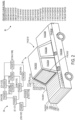
- a schematic diagram of a modeling system 10 comprising a server computing device 12 which includes one or more processors 14, which can be communicatively coupled to a network 22.
- the server computing device 12 further comprises non-volatile memory 16 storing a three-dimensional (3D) virtual model 30 and instructions 32 that, when executed by the processor 14, cause the processor 14 to retrieve the 3D virtual model 30 from the non-volatile memory 16.
- the 3D virtual model 30 can be of an aircraft or an aircraft component, or other manufactured parts or components, for example, as illustrated in Fig. 8.
- the sizes of the 3D virtual model 30 are not particularly limited-the 3D virtual model 30 can be of micron-scale objects in such applications as printed circuit boards or medical devices, or of over-sized objects.
- the 3D virtual model 30 is the mathematical representation of the surface geometry of an object, so that computer-rendered images of the object can be created from any angle.
- the 3D virtual model 30 can be a polygon mesh model.
- the non-volatile memory 16 can further store a U-V mapping 40, onto which one or more feature curves of the 3D virtual model 30 can be projected to produce a plurality of two dimensional curves (U-V curves).
- the U-V mapping is a parameterized surface and can be a piecewise polynomial mapping, such as a tensor product spline, between a two-dimensional rectangular parameter domain and three-dimensional space.
- the server computing device 12 includes a network interface 18 to affect the communicative coupling to the network 22 and, through the network 22, a client computing device 24.
- the client computing device 24 comprises a display 28 which is configured to display a parameterized surface 42 which is outputted by the server computing device 12.
- Network interface 18 can include a physical network interface, such as a network adapter.
- the server computing device 12 can be a special-purpose computer, adapted for reliability and high-bandwidth communications.
- the system 10 can be embodied in a cluster of individual hardware server computers, for example.
- the processor 14 can be multi-core processors suitable for handling large amounts of information.
- the processor 14 is communicatively coupled to non-volatile memory 16 storing a 3D virtual model 30, U-V mapping 40, and instructions 32 which can be executed by the processor 14 to effectuate the techniques disclosed herein on concert with the client computing device 24 as shown and described below.
- the non-volatile memory 16 can be in a Redundant Array of Inexpensive Disk drives (RAID) configuration for added reliability.
- the processor 14 can also be communicatively coupled to graphical co-processors (GPU) 20. Graphical co-processors 20 can expedite the technique disclosed herein by performing operations in parallel.
- the processor 14 is configured to execute a modeling application 15.
- the modeling application 15 is configured to retrieve a 3D virtual model 30 of an object from the non-volatile memory 16, define a parameter domain, parameterize the 3D virtual model 30 over the parameter domain to thereby extract an outer surface of the 3D virtual model 30, the outer surface including a plurality of faces, identify feature curves and bounding boxes in each of the plurality of faces of the outer surface, generate a parameterized surface 42 from the identified feature curves, and output the feature curves and the parameterized surface 42.
- Fig. 2 shows an illustration of a connectivity graph 34 which maps points in 3D space to the feature curves.
- a 3D virtual model 30 of a toy car is shown with faces FACE01-FACE10 extracted as an outer surface of the 3D virtual model 30.
- the connectivity graph 34 shows the connectivity of the different faces to each other.
- the connectivity graph 34 can be a connectivity tree or graph mapping the feature curves to the plurality of faces, and mapping points in the 3D space to the feature curves.
- the connectivity graph 34 shows that FACE01 is connected to FACE02, FACE07, and FACE08.
- the feature curves extracted or identified in each face are also shown.
- FACE01 is shown to have feature curves C1 through C7
- FACE07 is shown to have feature curves C92 through C97.
- only feature curves with arc lengths that are longer than a predetermined minimum length can be extracted.
- a list 36 is generated of feature curve pairs that are proximate or adjacent to one another, which is subsequently used by the modeling application 15 to build a connectivity graph 34 mapping points in 3D space to the feature curves.
- nearby points can be found for each point in each feature curve using a spatial indexing scheme, which contains data about the relative proximities of the feature curves to each other.
- the spatial indexing scheme can be configured as an RTREE, for example.
- the corresponding curve is found for each nearby point to obtain a set of unique nearby feature curves.
- additional computations can be performed to determine whether two feature curves among the unique nearby feature curves are proximate or adjacent to each other.
- a principal axis of each feature curve can be calculated. It can be determined whether principal directions of the principal axes of the feature curves of the feature curve pair are aligned within a predetermined angle threshold. Responsive to determining that the principal directions of the principal axes of the feature curves of the feature curve pair are aligned within the predetermined angle threshold, the feature curve pair can be added to the list 36 of feature curve pairs that are adjacent to one another.
- midpoints and end points of each feature curve can be projected. It can be determined whether the midpoints and the end points are separated within a predetermined distance. Responsive to determining that the midpoints and the end points are separated within the predetermined distance, the feature curve pair can be added to the list 36 of feature curve pairs that are adjacent to one another.
- the predetermined distance can be half a difference between the arc lengths of the feature curves of the feature curve pair, for example.
- the process of extracting features from the 3D virtual model 30 via the connectivity graph is schematically illustrated for three of the faces: face 01, face 03, and face 07.
- the small arrows on each of the three faces represent normals of each face.
- the normals of the connected faces are compared, and added as a feature if the angle difference between the normals is greater than a predetermined threshold.
- the predetermined threshold may be set between 45 to 90 degrees, for example.
- the angle difference between the normals of face 01 and face 07 is determined to be greater than a predetermined threshold, so a first feature 38a is extracted between face 01 and face 07.
- the angle difference between the normals of face 01 and face 03 is determined to be greater than a predetermined threshold, so a second feature 38b is extracted between face 01 and face 03. Boundaries 38c around the faces 01, 03, 07 are subsequently extracted. When missing faces are detected, the faces are added, and the connectivity graph is updated.
- the two faces corresponding to the feature curve pair are obtained, and the two faces are added to the connectivity graph 34.
- the two faces corresponding to feature curves C7 and C8 are identified as face 01 and face 02, respectively.
- the two faces corresponding to feature curves C1 and C92 are identified as face 01 and face 07, respectively.
- the modeling application 15 obtains face pairs corresponding to the feature curve pairs to obtain a list 36 of faces in the outer surface of the 3D virtual model 30, and then adds this list 36 of faces to the connectivity graph 34.
- the list of features is subsequently outputted.
- the features 38a, 38b can be organized and the curves joined into single features.
- a parameterized surface 42 can be generated from the generated feature curves.
- the feature curves C1-C199 and the parameterized surface 42 are subsequently outputted.
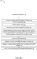
- Figs. 4A and 4B show an exemplary modeling method 100 according to an example of the present disclosure.
- the following description of method 100 is provided with reference to the software and hardware components described above and shown in Figs. 1 through 3 . It will be appreciated that method 100 also can be performed in other contexts using other suitable hardware and software components.
- a 3D virtual model is retrieved.
- an outer surface of the 3D virtual model is extracted, the outer surface including a plurality of faces.
- feature curves in each of the plurality of faces of the outer surface are identified.
- Step 106 can include a step 106a of identifying feature curves in each of the plurality of faces of the outer surface with arc lengths that are longer than a predetermined minimum length.
- a connectivity graph is built for the one or more feature curves, which maps points in 3D space to the feature curves.
- Step 110 can include steps 110a-f.
- all points are identified for each feature curve.
- nearby points are found for each point in each feature curve using a spatial indexing scheme.
- the corresponding curve is found for each nearby point to obtain a set of unique nearby feature curves.
- Step 110d determines whether two feature curves among the unique nearby feature curves are proximate or adjacent to each other. This can be done by calculating geometric distance, for example, using a distance function, and determining that the approximate Hausdorff distance between the two feature curves is less than a predetermined threshold distance.
- the feature curve pair is appended to a list of feature curve pairs to generate the list of feature curve pairs that are proximate or adjacent to one another.
- the two faces corresponding to the feature curve pair are identified to obtain face pairs corresponding to the feature curve pairs and obtain a list of faces in the outer surface, and the list of faces in the outer surface is added to the connectivity graph.
- the features are extracted from the connectivity graph.
- Step 112 can include steps 112a-d.
- steps 112a boundaries are extracted.
- steps 112b missing faces are detected.
- steps 112c the faces are repaired, and the connectivity graph is updated.
- the normals for each pair of connected faces are computed and compared, evaluating whether an angle difference between normal of the connected faces is greater than a predetermined threshold.
- a feature curve is extracted based on the pair of connected faces, and added as a feature responsive to determining that the angle difference between the normals is greater than a threshold.
- the list of features is outputted.
- the features are organized, and the curves are joined into single features.
- a parameterized surface is generated from the generated feature curves.
- the feature curves and the parameterized surface are outputted.
- Fig. 5 is an image of an aircraft 200 according to some embodiments. It will be appreciated that the aircraft 200 or a component 202 thereof can be the object that is modeled by the 3D virtual model 30 in accordance with the system 10 and method 100 of the subject disclosure.
- the systems and processes described herein have the potential benefit of building 3D parameterized surfaces that model complicated shapes accurately and efficiently without using an excessive number of control points, so that the feature curves of the 3D virtual model track the features of the 3D virtual model, including sharp edges or corners of the 3D virtual model, even on parts with complex geometric curvatures, such as wing panels of airplanes with many polygonal faces.
- the 3D virtual model of the present disclosure improves accuracy.
- the model becomes easier to work with for designers and programmers.
- designers and programmers would synthesize data represented in multiple separate geometric patches for each feature detected in the model, which was processor and memory intensive, so that the synthesized model could be input into analysis software programs.
- the 3D virtual model of the present disclosure can save processor and memory resources by avoiding such laborious synthesis of separate geometries.
- by detecting sharp feature curves on the 3D virtual model they can be used as engineering features in computer-aided design (CAD) applications, thereby improving the technical compatibility of the model as compared to prior approaches.
- CAD computer-aided design
- the parameterized surfaces outputted by the systems and processes described herein can be used in various applications.
- the parameterized surfaces can be used in additive manufacturing applications, for example, to optimize the weight, cost, and/or function of a 3D manufactured object through 3D model modifications.
- the parameterized surfaces can also be used to detect surface anomalies during inspection of the skin of manufactured or assembled parts of aircraft using three-dimensional modeling, for example.
- Fig. 6 illustrates an exemplary computing system 300 that can be utilized to implement the system 10 and method 100 described above.
- Computing system 300 includes a logic processor 302, volatile memory 304, and a non-volatile storage device 306.
- Computing system 300 can optionally include a display subsystem 308, input subsystem 310, communication subsystem 312 connected to a computer network, and/or other components not shown in Fig. 6 . These components are typically connected for data exchange by one or more data buses when integrated into single device, or by a combination of data buses, network data interfaces, and computer networks when integrated into separate devices connected by computer networks.
- the non-volatile storage device 306 stores various instructions, also referred to as software, that are executed by the logic processor 302.
- Logic processor 302 includes one or more physical devices configured to execute the instructions.
- the logic processor 302 can be configured to execute instructions that are part of one or more applications, programs, routines, libraries, objects, components, data structures, or other logical constructs. Such instructions can be implemented to perform a task, implement a data type, transform the state of one or more components, achieve a technical effect, or otherwise arrive at a desired result.
- the logic processor 302 can include one or more physical processors (hardware) configured to execute software instructions. Additionally or alternatively, the logic processor 302 can include one or more hardware logic circuits or firmware devices configured to execute hardware-implemented logic or firmware instructions. Processors of the logic processor 302 can be single-core or multi-core, and the instructions executed thereon can be configured for sequential, parallel, and/or distributed processing. Individual components of the logic processor 302 optionally can be distributed among two or more separate devices, which can be remotely located and/or configured for coordinated processing. Aspects of the logic processor 302 can be virtualized and executed by remotely accessible, networked computing devices configured in a cloud-computing configuration. In such a case, these virtualized aspects are run on different physical logic processors of various different machines, it will be understood.
- Non-volatile storage device 306 includes one or more physical devices configured to hold instructions executable by the logic processors to implement the methods and processes described herein. When such methods and processes are implemented, the state of non-volatile storage device 306 can be transformed-e.g., to hold different data.
- Non-volatile storage device 306 can include physical devices that are removable and/or built-in.
- Non-volatile storage device 306 can include optical memory (e.g., CD, DVD, HD-DVD, Blu-Ray Disc, etc.), semiconductor memory (e.g., ROM, EPROM, EEPROM, FLASH memory, etc.), and/or magnetic memory (e.g., hard-disk drive, floppy-disk drive, tape drive, MRAM, etc.), or other mass storage device technology.
- Non-volatile storage device 306 can include nonvolatile, dynamic, static, read/write, read-only, sequential-access, location-addressable, file-addressable, and/or content-addressable devices. It will be appreciated that non-volatile storage device 306 is configured to hold instructions even when power is cut to the non-volatile storage device 306.
- Volatile memory 304 can include physical devices that include random access memory. Volatile memory 304 is typically utilized by logic processor 302 to temporarily store information during processing of software instructions. It will be appreciated that volatile memory 304 typically does not continue to store instructions when power is cut to the volatile memory 304.
- logic processor 302, volatile memory 304, and non-volatile storage device 306 can be integrated together into one or more hardware-logic components.
- hardware-logic components can include field-programmable gate arrays (FPGAs), program- and application-specific integrated circuits (PASIC / ASICs), program- and application-specific standard products (PSSP / ASSPs), system-on-a-chip (SOC), and complex programmable logic devices (CPLDs), for example.
- FPGAs field-programmable gate arrays
- PASIC / ASICs program- and application-specific integrated circuits
- PSSP / ASSPs program- and application-specific standard products
- SOC system-on-a-chip
- CPLDs complex programmable logic devices
- module can be used to describe an aspect of the modeling system 10 typically implemented in software by a processor to perform a particular function using portions of volatile memory, which function involves transformative processing that specially configures the processor to perform the function.
- a module, program, or engine can be instantiated via logic processor 302 executing instructions held by non-volatile storage device 306, using portions of volatile memory 304.
- modules, programs, and/or engines can be instantiated from the same application, service, code block, object, library, routine, API, function, etc.
- the same module, program, and/or engine can be instantiated by different applications, services, code blocks, objects, routines, APIs, functions, etc.
- module can encompass individual or groups of executable files, data files, libraries, drivers, scripts, database records, etc.
- Display subsystem 308 typically includes one or more displays, which can be physically integrated with or remote from a device that houses the logic processor 302. Graphical output of the logic processor executing the instructions described above, such as a graphical user interface, is configured to be displayed on display subsystem 308.
- Input subsystem 310 typically includes one or more of a keyboard, pointing device (e.g., mouse, trackpad, finger operated pointer), touchscreen, microphone, and camera. Other input devices can also be provided.
- Communication subsystem 312 is configured to communicatively couple various computing devices described herein with each other, and with other devices.
- Communication subsystem 312 can include wired and/or wireless communication devices compatible with one or more different communication protocols.
- the communication subsystem can be configured for communication via a wireless telephone network, or a wired or wireless local- or wide-area network by devices such as a 3G, 4G, 5G, or 6G radio, WIFI card, ethernet network interface card, BLUETOOTH radio, etc.
- the communication subsystem can allow computing system 10 to send and/or receive messages to and/or from other devices via a network such as the Internet.
- one or more of the computer networks via which communication subsystem 312 is configured to communicate can include security measures such as user identification and authentication, access control, malware detection, enforced encryption, content filtering, etc., and can be coupled to a wide area network (WAN) such as the Internet.
- security measures such as user identification and authentication, access control, malware detection, enforced encryption, content filtering, etc.
- WAN wide area network
- the subject disclosure includes all novel and non-obvious combinations and subcombinations of the various features and techniques disclosed herein.
- the various features and techniques disclosed herein are not necessarily required of all examples of the subject disclosure.
- the various features and techniques disclosed herein can define patentable subject matter apart from the disclosed examples and can find utility in other implementations not expressly disclosed herein.
Landscapes
- Physics & Mathematics (AREA)
- Engineering & Computer Science (AREA)
- General Physics & Mathematics (AREA)
- Geometry (AREA)
- Theoretical Computer Science (AREA)
- Software Systems (AREA)
- Computer Graphics (AREA)
- Mathematical Analysis (AREA)
- Pure & Applied Mathematics (AREA)
- Mathematical Optimization (AREA)
- Algebra (AREA)
- Mathematical Physics (AREA)
- Computer Hardware Design (AREA)
- Evolutionary Computation (AREA)
- General Engineering & Computer Science (AREA)
- Computational Mathematics (AREA)
- Computer Vision & Pattern Recognition (AREA)
- Processing Or Creating Images (AREA)
Applications Claiming Priority (1)
| Application Number | Priority Date | Filing Date | Title |
|---|---|---|---|
| US17/929,531 US12198270B2 (en) | 2022-09-02 | 2022-09-02 | Modeling system for 3D virtual model |
Publications (1)
| Publication Number | Publication Date |
|---|---|
| EP4332816A1 true EP4332816A1 (fr) | 2024-03-06 |
Family
ID=87517268
Family Applications (1)
| Application Number | Title | Priority Date | Filing Date |
|---|---|---|---|
| EP23188210.1A Pending EP4332816A1 (fr) | 2022-09-02 | 2023-07-27 | Système de modélisation pour modèle virtuel 3d |
Country Status (3)
| Country | Link |
|---|---|
| US (1) | US12198270B2 (fr) |
| EP (1) | EP4332816A1 (fr) |
| CN (1) | CN117649483A (fr) |
Families Citing this family (1)
| Publication number | Priority date | Publication date | Assignee | Title |
|---|---|---|---|---|
| US12272018B2 (en) * | 2022-07-15 | 2025-04-08 | The Boeing Company | Modeling system for 3D virtual model |
Citations (1)
| Publication number | Priority date | Publication date | Assignee | Title |
|---|---|---|---|---|
| US20130124149A1 (en) * | 2009-08-21 | 2013-05-16 | Nathan A. Carr | System and Method for Creating Editable Feature Curves for a Multi-Dimensional Model |
Family Cites Families (1)
| Publication number | Priority date | Publication date | Assignee | Title |
|---|---|---|---|---|
| EP2750108B1 (fr) * | 2012-12-28 | 2019-05-01 | Dassault Systèmes | Paramétrage d'un objet modélisé en 3D pour mosaïque |
-
2022
- 2022-09-02 US US17/929,531 patent/US12198270B2/en active Active
-
2023
- 2023-07-27 EP EP23188210.1A patent/EP4332816A1/fr active Pending
- 2023-07-31 CN CN202310956466.8A patent/CN117649483A/zh active Pending
Patent Citations (1)
| Publication number | Priority date | Publication date | Assignee | Title |
|---|---|---|---|---|
| US20130124149A1 (en) * | 2009-08-21 | 2013-05-16 | Nathan A. Carr | System and Method for Creating Editable Feature Curves for a Multi-Dimensional Model |
Non-Patent Citations (1)
| Title |
|---|
| JOEL II DANIELS ET AL: "Robust Smooth Feature Extraction from Point Clouds", SHAPE MODELING AND APPLICATIONS, 2007. SMI '07. IEEE INTERNATIONAL CON FERENCE ON, IEEE, PI, 1 June 2007 (2007-06-01), pages 123 - 136, XP031116740, ISBN: 978-0-7695-2815-1 * |
Also Published As
| Publication number | Publication date |
|---|---|
| CN117649483A (zh) | 2024-03-05 |
| US20240078752A1 (en) | 2024-03-07 |
| US12198270B2 (en) | 2025-01-14 |
Similar Documents
| Publication | Publication Date | Title |
|---|---|---|
| US9928645B2 (en) | Raster-based mesh decimation | |
| EP3321817B1 (fr) | Interrogation d'une base de données basée sur une fonction de vue paramétrique | |
| US20220289403A1 (en) | System and method for automated surface anomaly detection | |
| EP3264286B1 (fr) | Interrogation d'une base de données à l'aide de critère morphologique | |
| US11163916B2 (en) | Automatic generation of dimension and tolerance information for fastened components | |
| US10747913B2 (en) | Goal-driven computer aided design workflow | |
| US11727166B2 (en) | Techniques for generating graph-based representations of complex mechanical assemblies | |
| EP4307235A1 (fr) | Système de modélisation pour modèle virtuel 3d appliquant une reparametrisation de surface | |
| EP4332816A1 (fr) | Système de modélisation pour modèle virtuel 3d | |
| EP2407902A2 (fr) | Système et procédé de configuration d'un modèle de simulation utilisant un outil pour attribution automatique d'entrée/sortie | |
| CN108364327A (zh) | 一种图数据处理的方法及装置 | |
| JP5790874B2 (ja) | 形状変更方法 | |
| US11551130B2 (en) | Quantum computing device model discretization | |
| US20250148169A1 (en) | Mirror Finite Element Mesh Generation | |
| US10042962B2 (en) | Mid-surface extraction for finite element analysis | |
| CN120821865A (zh) | 局部拓扑相似度检索的方法、程序、存储介质和计算机 | |
| CN103970925A (zh) | 撞击事件数字模拟中的、包括低阶和二次有限元的接触表面定义标准 | |
| CN118379426A (zh) | 一种三维模型表征方法、装置、设备和存储介质 | |
| US11481524B2 (en) | Conformal coating iteration | |
| EP4550195A1 (fr) | Génération des éléments finis par miroiter | |
| US12056838B2 (en) | Computer-automated separation rules compliance analysis | |
| US20030163604A1 (en) | Method and apparatus for design and manufacturing application feature interoperability | |
| CN120937011A (zh) | 在计算机辅助设计环境中组装几何组件的方法和系统 | |
| WO2025193603A1 (fr) | Inspection de réalité augmentée à auto-validation d'un composant |
Legal Events
| Date | Code | Title | Description |
|---|---|---|---|
| PUAI | Public reference made under article 153(3) epc to a published international application that has entered the european phase |
Free format text: ORIGINAL CODE: 0009012 |
|
| STAA | Information on the status of an ep patent application or granted ep patent |
Free format text: STATUS: THE APPLICATION HAS BEEN PUBLISHED |
|
| AK | Designated contracting states |
Kind code of ref document: A1 Designated state(s): AL AT BE BG CH CY CZ DE DK EE ES FI FR GB GR HR HU IE IS IT LI LT LU LV MC ME MK MT NL NO PL PT RO RS SE SI SK SM TR |
|
| STAA | Information on the status of an ep patent application or granted ep patent |
Free format text: STATUS: REQUEST FOR EXAMINATION WAS MADE |
|
| 17P | Request for examination filed |
Effective date: 20240906 |
|
| RBV | Designated contracting states (corrected) |
Designated state(s): AL AT BE BG CH CY CZ DE DK EE ES FI FR GB GR HR HU IE IS IT LI LT LU LV MC ME MK MT NL NO PL PT RO RS SE SI SK SM TR |