EP4332884A1 - Détection d'anomalies anatomiques dans des images médicales 2d - Google Patents
Détection d'anomalies anatomiques dans des images médicales 2d Download PDFInfo
- Publication number
- EP4332884A1 EP4332884A1 EP22193692.5A EP22193692A EP4332884A1 EP 4332884 A1 EP4332884 A1 EP 4332884A1 EP 22193692 A EP22193692 A EP 22193692A EP 4332884 A1 EP4332884 A1 EP 4332884A1
- Authority
- EP
- European Patent Office
- Prior art keywords
- anatomical
- model
- contour
- medical image
- abnormality
- Prior art date
- Legal status (The legal status is an assumption and is not a legal conclusion. Google has not performed a legal analysis and makes no representation as to the accuracy of the status listed.)
- Withdrawn
Links
Images


Classifications
-
- G—PHYSICS
- G06—COMPUTING OR CALCULATING; COUNTING
- G06T—IMAGE DATA PROCESSING OR GENERATION, IN GENERAL
- G06T7/00—Image analysis
- G06T7/0002—Inspection of images, e.g. flaw detection
- G06T7/0012—Biomedical image inspection
- G06T7/0014—Biomedical image inspection using an image reference approach
-
- A—HUMAN NECESSITIES
- A61—MEDICAL OR VETERINARY SCIENCE; HYGIENE
- A61B—DIAGNOSIS; SURGERY; IDENTIFICATION
- A61B6/00—Apparatus or devices for radiation diagnosis; Apparatus or devices for radiation diagnosis combined with radiation therapy equipment
- A61B6/50—Apparatus or devices for radiation diagnosis; Apparatus or devices for radiation diagnosis combined with radiation therapy equipment specially adapted for specific body parts; specially adapted for specific clinical applications
- A61B6/505—Apparatus or devices for radiation diagnosis; Apparatus or devices for radiation diagnosis combined with radiation therapy equipment specially adapted for specific body parts; specially adapted for specific clinical applications for diagnosis of bone
-
- A—HUMAN NECESSITIES
- A61—MEDICAL OR VETERINARY SCIENCE; HYGIENE
- A61B—DIAGNOSIS; SURGERY; IDENTIFICATION
- A61B6/00—Apparatus or devices for radiation diagnosis; Apparatus or devices for radiation diagnosis combined with radiation therapy equipment
- A61B6/52—Devices using data or image processing specially adapted for radiation diagnosis
- A61B6/5211—Devices using data or image processing specially adapted for radiation diagnosis involving processing of medical diagnostic data
- A61B6/5223—Devices using data or image processing specially adapted for radiation diagnosis involving processing of medical diagnostic data generating planar views from image data, e.g. extracting a coronal view from a 3D image
-
- G—PHYSICS
- G06—COMPUTING OR CALCULATING; COUNTING
- G06T—IMAGE DATA PROCESSING OR GENERATION, IN GENERAL
- G06T19/00—Manipulating three-dimensional [3D] models or images for computer graphics
-
- G—PHYSICS
- G06—COMPUTING OR CALCULATING; COUNTING
- G06T—IMAGE DATA PROCESSING OR GENERATION, IN GENERAL
- G06T7/00—Image analysis
- G06T7/10—Segmentation; Edge detection
- G06T7/12—Edge-based segmentation
-
- G—PHYSICS
- G06—COMPUTING OR CALCULATING; COUNTING
- G06T—IMAGE DATA PROCESSING OR GENERATION, IN GENERAL
- G06T7/00—Image analysis
- G06T7/10—Segmentation; Edge detection
- G06T7/13—Edge detection
-
- G—PHYSICS
- G06—COMPUTING OR CALCULATING; COUNTING
- G06T—IMAGE DATA PROCESSING OR GENERATION, IN GENERAL
- G06T7/00—Image analysis
- G06T7/70—Determining position or orientation of objects or cameras
- G06T7/73—Determining position or orientation of objects or cameras using feature-based methods
- G06T7/74—Determining position or orientation of objects or cameras using feature-based methods involving reference images or patches
-
- G—PHYSICS
- G06—COMPUTING OR CALCULATING; COUNTING
- G06V—IMAGE OR VIDEO RECOGNITION OR UNDERSTANDING
- G06V10/00—Arrangements for image or video recognition or understanding
- G06V10/20—Image preprocessing
- G06V10/26—Segmentation of patterns in the image field; Cutting or merging of image elements to establish the pattern region, e.g. clustering-based techniques; Detection of occlusion
-
- G—PHYSICS
- G06—COMPUTING OR CALCULATING; COUNTING
- G06V—IMAGE OR VIDEO RECOGNITION OR UNDERSTANDING
- G06V10/00—Arrangements for image or video recognition or understanding
- G06V10/40—Extraction of image or video features
- G06V10/44—Local feature extraction by analysis of parts of the pattern, e.g. by detecting edges, contours, loops, corners, strokes or intersections; Connectivity analysis, e.g. of connected components
-
- G—PHYSICS
- G06—COMPUTING OR CALCULATING; COUNTING
- G06V—IMAGE OR VIDEO RECOGNITION OR UNDERSTANDING
- G06V10/00—Arrangements for image or video recognition or understanding
- G06V10/70—Arrangements for image or video recognition or understanding using pattern recognition or machine learning
- G06V10/764—Arrangements for image or video recognition or understanding using pattern recognition or machine learning using classification, e.g. of video objects
-
- G—PHYSICS
- G06—COMPUTING OR CALCULATING; COUNTING
- G06T—IMAGE DATA PROCESSING OR GENERATION, IN GENERAL
- G06T2207/00—Indexing scheme for image analysis or image enhancement
- G06T2207/10—Image acquisition modality
- G06T2207/10116—X-ray image
-
- G—PHYSICS
- G06—COMPUTING OR CALCULATING; COUNTING
- G06T—IMAGE DATA PROCESSING OR GENERATION, IN GENERAL
- G06T2207/00—Indexing scheme for image analysis or image enhancement
- G06T2207/10—Image acquisition modality
- G06T2207/10116—X-ray image
- G06T2207/10121—Fluoroscopy
-
- G—PHYSICS
- G06—COMPUTING OR CALCULATING; COUNTING
- G06T—IMAGE DATA PROCESSING OR GENERATION, IN GENERAL
- G06T2207/00—Indexing scheme for image analysis or image enhancement
- G06T2207/20—Special algorithmic details
- G06T2207/20092—Interactive image processing based on input by user
-
- G—PHYSICS
- G06—COMPUTING OR CALCULATING; COUNTING
- G06T—IMAGE DATA PROCESSING OR GENERATION, IN GENERAL
- G06T2207/00—Indexing scheme for image analysis or image enhancement
- G06T2207/30—Subject of image; Context of image processing
- G06T2207/30004—Biomedical image processing
- G06T2207/30008—Bone
-
- G—PHYSICS
- G06—COMPUTING OR CALCULATING; COUNTING
- G06T—IMAGE DATA PROCESSING OR GENERATION, IN GENERAL
- G06T2210/00—Indexing scheme for image generation or computer graphics
- G06T2210/41—Medical
-
- G—PHYSICS
- G06—COMPUTING OR CALCULATING; COUNTING
- G06V—IMAGE OR VIDEO RECOGNITION OR UNDERSTANDING
- G06V2201/00—Indexing scheme relating to image or video recognition or understanding
- G06V2201/03—Recognition of patterns in medical or anatomical images
- G06V2201/033—Recognition of patterns in medical or anatomical images of skeletal patterns
Definitions
- the invention relates to a computer-implemented method, a computer program product, and a system configured for detecting anatomical abnormalities in 2D medical images.
- Medical images are often used for diagnostic purposes. For example, medical images are examined by human observers for anatomical abnormalities. Examples of such abnormalities include bone fractures and tumorous tissue, which may be identified in X-ray, ultrasound, CT (Computer Tomography) or other medical images.
- An aspect of the present invention provides a computer-implemented method for detecting an anatomical abnormality in a 2D medical image.
- the method comprises
- the step of detecting a 2D contour may further include segmenting the 2D medical image. For example, individual pixels of an acquired medical image may be labeled as "bone/no bone", such as to identify bones in the image, and thereby detecting the 2D contours.
- the step of detecting a 2D contour may include an end-to-end trained machine learning algorithm.
- the step of detecting a 2D contour may include identifying an anatomical feature. For example, identifying that the 2D contour is that of one or more bones of an ankle joint or a wrist. This approach may further be used to optimize the workflow of any further processing or to provide guidance to the user or machine for further steps.
- the method may further include classifying the anatomical abnormality.
- the step of classifying the anatomical abnormality may further be performed by a machine learning algorithm.
- the output of the computer-implemented method is not binary, e.g. anatomical abnormality detected or not detected, but provides the user insight into the classification of said abnormality. For example, whether it is severe or not, and/or whether it is a specific type of bone fracture and/or ligament rupture.
- the 3D model is obtained based on
- the 3D model may further be any one of:
- the method further comprises
- a difference map may be generated. Said difference map containing information suitable to be displayed on a display.
- the step of predicting a 2D contour of the anatomical feature based on the 3D model comprises:
- the anatomical feature is any one of
- the anatomical abnormality is any one of
- the step of classifying the anatomical abnormality classifies the anatomical abnormality according to any one of
- the medical image is an X-ray image.
- Another aspect of the invention provides a computer program product comprising instructions for enabling a processor to carry out an embodiment of the above method.
- Yest another aspect of the invention provides a system for detecting an anatomical abnormality in a 2D medical image.
- the system comprising a processor configured to
- the system may further comprise an X-ray source and detector configured for taking an X-ray image.
- the invention provides a computer-implemented method of analyzing and assessing 2D (two-dimensional) medical images with the purpose of identifying anatomical abnormalities.
- Fig. 1 shows an exemplary flow chart according to an embodiment of a method 100 according to the invention that comprises the following steps:
- a 2D medical image 210 is obtained.
- the 2D medical image may be any type of medical image, including but not limited to for example an X-ray image, a CT (computer tomography) image, an ultrasound image, an MR (magnetic resonance) image, or any other type of medical image.
- An exemplary medical image 210 as envisaged in this invention is the 2D X-ray image of an ankle joint 211 shown in Fig. 2A .
- a 2D contour of an anatomical feature is detected. This may for example include a segmentation of the 2D medical image or an end-to-end machine learning approach.
- segmentation may be understood as the task of classifying an image per pixel into labels.
- the classification is per larger image regions as whole, such as contours or surfaces.
- the labels represent a semantics of the respective pixel or image region.
- a bone pixel that is, a pixel having the label "bone”
- the pixel is then thought to represent bone tissue, and so forth for other tissue types. Footprints of organs in the imagery can thus be identified by segmentation.
- the segmentation may be performed using a neural network or a convolutional neural network, such as disclosed in WO 2022/084074 . Algorithms including prior shape knowledge as disclosed therein are also envisaged by this invention.
- a segmented image is typically obtained, in which each pixel and/or region has a specific label assigned to it.
- This label may be binary "bone/no bone” or multilevel “bone/ligament tissue/no bone/... ".
- the parts in the medical image corresponding with an anatomical feature of interest for example “bone” or more specifically, “tibia/fibula/calcaneus/talus", may be selected to generate a 2D contour 212 as shown in Fig. 2B .
- a 3D (three-dimensional) model 330 representative of the imaged object 211 or the identified anatomical feature 213 is obtained.
- the model may be selected from a list of 3D models based on at least one of:
- the image 210 obtained in step 110 may be annotated to indicate that the image is of an ankle joint.
- the identified anatomical feature or combination of identified anatomical features may indicate that the image contains at least an ankle joint.
- a DICOM tag may be associated with the anatomical feature being imaged, which may be used to identify the 3D model.
- a user of a computing system executing the method 100 may select the 3D model from a list of models. The user selection may be from the entirety of all 3D models, or from a reduced set of articulated 3D models, which may be pre-selected based on the 2D medical image and/or identified anatomical features in the 2D medical image.
- the 3D model may be selected based on context information at the acquisition place, e.g. Radiology department in a hospital, based on for example user diagnostic request data and/or radiological standard operation procedure for a requested examination procedure.
- context information at the acquisition place e.g. Radiology department in a hospital
- a user or operator may indicate a desire to take an ankle joint X-ray image, which may determine the relevant 3D model, or create a pre-selection of relevant 3D models.
- the 3D model may be articulated such as to be able to account for different poses of the imaged object, for example the 3D model may be capable of reproducing a specific flexion of an ankle joint.
- a representative 3D model may be a computer aided design (CAD) model, created with any CAD software, or a reference model extracted from 3D imaging using known techniques. For example, a sequence of MR images of an ankle joint of a healthy subject may be obtained at varying flexion angles. One image may then be segmented manually or automatically according to known techniques. The segmented image may then be used to create a surface-model using for example a triangular mesh. For each triangle in the mesh, features for model-adaption may then be trained using for example the image intensity, and the resulting model may be used to delineate corresponding bone surfaces in the other MR images. This procedure may yield a 3D model per MR image.
- CAD computer aided design
- the pose in each image and/or corresponding 3D model may further be determined by for example measuring the angle between the main axis of the tibia and that of the calcaneus for flexion. Smooth interpolation of the surface models between the varying poses recorded in the MR images, may enable the mesh constellation to be estimated at any pose therebetween.
- a 3D model 430 as envisaged by the invention is shown in Fig. 4 .
- the 3D model may be articulated and may be modified such as to fit any pose encountered in a 2D medical image.
- the calcaneus is shown to rotate with respect to the tibia from 80 degrees to 135 degrees flexion.
- a 2D contour of the anatomical features in the medical image is predicted from a 3D model.
- the contour may be predicted according to the following steps:
- the viewing parameters and pose as referred to in step 142 may be, as shown in Fig. 3 for an ankle joint, any one of for example:
- the pose and/or viewing parameters may be estimated in step 142 according to S. Krönke et al. 2022 "CNN-based pose estimation for assessing quality of ankle-joint X-ray images”.
- a meshed 3D model of an ankle joint may be sampled at random flexion angles and viewing directions, and projections may be generated by identifying the triangles of the mesh in the 3D model which are traversed by the X-ray beam approximately tangentially for the chosen viewing direction, projecting their edges onto the virtual detector and semantically grouping and discretizing them on a detector pixel-matrix.
- the resulting set of discretized contours in the projections forms the input for a pose-estimation network.
- a pose-estimation network may be a standard regression network involving ReLU (Rectified Linear Unit) activation functions with alternating stride-1 and stride-2 convolutional blocks and fully connected layers.
- ReLU Rectified Linear Unit
- a network trained according to the above principle may then be used to predict the pose of detected 2D contours.
- 2D contours of an imaged ankle joint will be fed into the neural network, which may, due to its training, provide the flexion angle and viewing direction of the imaged ankle joint.
- the pose and/or viewing parameters estimated in step 142 may then be used as input to step 144 in modifying or adjusting the 3D model to reproduce the respective pose and/or viewing parameters.
- the flexion angle of the 3D ankle model 430 may be varied as shown in Fig. 4 , where the angle between the tibia and calcaneus is changed from 80 degrees to 135 degrees.
- a 2D projection is determined in a step 146 by for example identifying the triangles of the mesh in the 3D model which are traversed by an X-ray beam approximately tangentially for the chosen viewing direction, projecting their edges onto a virtual detector and semantically grouping and discretizing them on a detector pixel-matrix, thereby also directly providing the predicted 2D contours of step 148.
- Fig. 2C shows exemplary 2D contours 214 as predicted in step 140, 142-148 from a 3D model of an ankle joint.
- a difference between the 2D contours generated based on the 2D medical image and the 2D contours generated based on the articulated 3D model may be determined. This difference may be calculated based on for example a pointwise subtraction or pixel-by-pixel subtraction. In some implementations, a difference map may be created, wherein said difference map may also be visualized on a user interface (not shown).
- an anatomical abnormality is detected based on the 2D contours respectively detected in step 120 and predicted in step 140.
- the anatomical abnormality may be detected by visual inspection of for example a difference map shown on a user interface (not shown).
- the anatomical abnormality may be detected automatically. For example, based on whether a difference or a deviation between (i) the 2D contours generated based on the 2D medical image and (ii) the 2D contours generated based on the articulated 3D model exceeds a particular threshold.
- a machine learning algorithm may be used to detect anatomical abnormalities.
- 2D medical images may be annotated by a user or expert to identify anatomical abnormalities.
- These annotated images may also be processed according to steps 120 and 140 in order to detect 2D contours and predict 2D contours, wherein the detected 2D contours, predicted 2D contours and/or a difference between the detected and predicted 2D contours may be added to the annotated images to be used in the training process.
- the identification of anatomical abnormalities may be binary, abnormality present or not present, or non-binary, in which case a probability may be provided that an abnormality is present.
- the anatomical abnormalities may also be classified in an optional step 160 based on size, location, or any other form of classification, to indicate a level of severity.
- the anatomical abnormality may be classified into a plurality of categories.
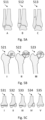
- Fig. 5A discussed in more detail below, shows for example a classification of ankle joint fractures
- Fig. 5B also discussed in more detail below, shows for example a classification of femoral neck fracture classification.
- the classification of the anatomical abnormality is performed with a trained machine learning algorithm.
- a classification network may be trained with annotated data such as in Fig. 5A-5C and using the detected 2D contours 212 and predicted 2D contours 214 as inputs.
- annotated medical images are provided.
- the annotations may be performed by an expert such as a clinician, radiologist, researcher or any other qualified person.
- an annotated image may be the ankle joint X-ray image 210 with an associated label of no fracture.
- Another example may be an ankle joint X-ray image with a fracture and corresponding label identifying the classification of said fracture. For example, whether the fracture is a type A, B or C fracture in the Weber classification.
- annotated images used for training also undergo steps 120 and 140 of method 100 in order to
- the detected 2D contours and predicted 2D contours may then form the input to a machine learning model, and the annotation of the training image the output.
- the training is performed with a subset of the training images and the corresponding annotations, and the remainder of the training images and corresponding annotations is used to evaluate the trained model.
- the training is stopped when a predetermined criterion is reached, such as to ensure that the model has been trained well enough but not over-trained.
- noise may manually or automatically be added to the training data to avoid over-fitting.
- the individual steps in the method 100 may be performed in real time, e.g., during an examination procedure, or thereafter.
- a 2D medical image may be obtained in real time and analyzed according to method 100 during the image acquisition procedure, or the 2D medical image may be first obtained during an acquisition step and only be analyzed upon request of an operator and/or expert.
- the method 100 may thus be implemented within an image acquisition system or outside of it in a separate computing unit. In another embodiment the method 100 may also be carried out in a cloud.
- Fig. 5A displays the Weber classification for ankle joints.
- type A 511 3 different types of fractures are shown, type B 512 and type C 513, which according to Wikipedia (https://en.wikipedia.org/wiki/Danis%E2%80%93Weber_classification) may be described as:
- Fractures of type B 512 and C 513 imply a degree of damage to the syndesmosis itself (which may not be directly visualized on X-ray). They are inherently unstable and are more likely to require operative repair to achieve a good outcome. Type A fractures are usually stable and can be managed with simple measures, such as a plaster of Paris cast. The correct identification of an ankle fracture according to the Weber classification may thus improve the outcome and/or recovery of the imaged subject.
- Fig. 5B displays the Pauwels classification for femoral neck fractures. These fractures are characterized by the fracturing angle. An increasing angle leads to a more unstable fracture and an increase in the shear stress at the fracture site. This shear leads to higher rates of nonunion. According to Wikipedia (https://en.wikipedia.org/wiki/Pauwel%27s_angle) the Pauwels classification, divides the fracture into type I 521, type II 522 and type III 523 fractures as follows:
- Fig. 5C displays the Salter-Harris classification for fractures involving the epiphyseal or growth plate of a bone, and specifically the zone of provisional calcification. It is thus a form of child bone fracture, occurring in 15% of childhood long bone fractures.
- the first five types may be described as:
- Fig. 5A to 5C are provided as a reference to showcase the classification possible according to embodiments of the present invention.
- using pre-defined classes allows an operator to see not only that a fracture may have occurred, but also what type of fracture may have occurred, and may thus improve the subsequent steps to improve the outcome and/or recovery of the imaged subject.
- a segmented tumor may automatically be classified according to its size and/or location into a stage I, stage II, stage III or stage IV tumor.
- the method 100 may further include an optional step 170 to provide treatment advice based on the identified anatomical abnormality and/or the classification result of the identified anatomical abnormality.
- the treatment advice may be immediate surgery needed to a type C Weber classified ankle fracture, while for a hairline and/or stress fracture, rest and/or cast may be advised.
- the advice may be based on annotated data, for example, the classification images may also be annotated to provide a treatment advice according to the classifications as discussed above.
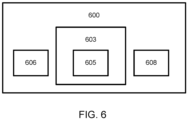
- Fig. 6 is a schematic diagram of a processor circuit 600, according to aspects of the present disclosure.
- the processor circuit 600 may include a processor 606, a memory 603, and a communication module 608. These elements may be in direct or indirect communication with each other, for example via one or more buses.
- the processor 606 may include a central processing unit (CPU), a graphical processing unit (GPU), a digital signal processor (DSP), an application specific integrated circuit (ASIC), a controller, a field programmable gate array (FPGA) device, another hardware device, a firmware device, or any combination thereof configured to perform the operations described herein.
- the processor 606 may also be implemented as a combination of computing devices, e.g., a combination of a DSP and a microprocessor, a plurality of microprocessors, one or more microprocessors in conjunction with a DSP core, or any other such configuration.
- the processor 606 may also implement various deep learning networks, which may include a hardware or a software implementation.
- the processor 606 may additionally include a preprocessor in either hardware or software implementation.
- the memory 603 as envisaged by the present disclosure may be any suitable storage device, such as a cache memory (e.g., a cache memory of the processor 606), random access memory (RAM), magnetoresistive RAM (MRAM), read-only memory (ROM), programmable read-only memory (PROM), erasable programmable read only memory (EPROM), electrically erasable programmable read only memory (EEPROM), flash memory, solid state memory device, hard disk drives, other forms of volatile and non-volatile memory, or a combination of different types of memory.
- the memory may be distributed among multiple memory devices and/or located remotely with respect to the processor circuit.
- the memory 603 may store instructions 605.
- the instructions 605 may include instructions that, when executed by a processor 606, cause the processor 606 to perform the operations described herein.
- Instructions 605 may also be referred to as code.
- the terms “instructions” and “code” should be interpreted broadly to include any type of computer-readable statement(s).
- the terms “instructions” and “code” may refer to one or more programs, routines, sub-routines, functions, procedures, etc.
- “Instructions” and “code” may include a single computer-readable statement or many computer-readable statements.
- Instructions 205 may be in the form of an executable computer program or script.
- routines, subroutines and/or functions may be defined in a programming language including but not limited to C, C++, C#, Pascal, BASIC, API calls, HTML, XHTML, XML, ASP scripts, JavaScript, FORTRAN, COBOL, Perl, Java, ADA, .NET, and the like. Instructions may also include instructions for machine learning and/or deep learning.
- the communication module 608 can include any electronic circuitry and/or logic circuitry to facilitate direct or indirect communication of data between the processor circuit 600, and for example an external display (not shown) and/or an imaging device or system such as an X-ray imaging system.
- the communication module 608 can be an input/output (I/O) device.
- the communication may be performed via any suitable means.
- the communication means may be a wired link, such as a universal serial bus (USB) link or an Ethernet link.
- the communication means may be a wireless link, such as an ultra-wideband (UWB) link, an Institute of Electrical and Electronics Engineers (IEEE) 802.11 Wi-Fi link, or a Bluetooth link.
- UWB ultra-wideband
- IEEE Institute of Electrical and Electronics Engineers
Landscapes
- Engineering & Computer Science (AREA)
- Health & Medical Sciences (AREA)
- Physics & Mathematics (AREA)
- Theoretical Computer Science (AREA)
- General Physics & Mathematics (AREA)
- Computer Vision & Pattern Recognition (AREA)
- Medical Informatics (AREA)
- Life Sciences & Earth Sciences (AREA)
- General Health & Medical Sciences (AREA)
- Radiology & Medical Imaging (AREA)
- Nuclear Medicine, Radiotherapy & Molecular Imaging (AREA)
- Multimedia (AREA)
- Biomedical Technology (AREA)
- Veterinary Medicine (AREA)
- Biophysics (AREA)
- Optics & Photonics (AREA)
- Pathology (AREA)
- Software Systems (AREA)
- High Energy & Nuclear Physics (AREA)
- Heart & Thoracic Surgery (AREA)
- Molecular Biology (AREA)
- Surgery (AREA)
- Animal Behavior & Ethology (AREA)
- Public Health (AREA)
- Quality & Reliability (AREA)
- Computing Systems (AREA)
- Orthopedic Medicine & Surgery (AREA)
- Dentistry (AREA)
- Oral & Maxillofacial Surgery (AREA)
- Artificial Intelligence (AREA)
- Computer Hardware Design (AREA)
- Databases & Information Systems (AREA)
- Evolutionary Computation (AREA)
- Computer Graphics (AREA)
- General Engineering & Computer Science (AREA)
- Apparatus For Radiation Diagnosis (AREA)
- Image Analysis (AREA)
Priority Applications (6)
| Application Number | Priority Date | Filing Date | Title |
|---|---|---|---|
| EP22193692.5A EP4332884A1 (fr) | 2022-09-02 | 2022-09-02 | Détection d'anomalies anatomiques dans des images médicales 2d |
| JP2025510283A JP2025530685A (ja) | 2022-09-02 | 2023-08-23 | 2d医用画像における解剖学的異常の検出 |
| EP23755442.3A EP4581567B1 (fr) | 2022-09-02 | 2023-08-23 | Détection d'anomalies anatomiques dans des images médicales 2d |
| CN202380062545.2A CN119816857A (zh) | 2022-09-02 | 2023-08-23 | 在2d医学图像中检测解剖异常 |
| US19/107,677 US20250371712A1 (en) | 2022-09-02 | 2023-08-23 | Detecting anatomical abnormalities in 2d medical images |
| PCT/EP2023/073073 WO2024046821A1 (fr) | 2022-09-02 | 2023-08-23 | Détection d'anomalies anatomiques dans des images médicales 2d |
Applications Claiming Priority (1)
| Application Number | Priority Date | Filing Date | Title |
|---|---|---|---|
| EP22193692.5A EP4332884A1 (fr) | 2022-09-02 | 2022-09-02 | Détection d'anomalies anatomiques dans des images médicales 2d |
Publications (1)
| Publication Number | Publication Date |
|---|---|
| EP4332884A1 true EP4332884A1 (fr) | 2024-03-06 |
Family
ID=83448037
Family Applications (2)
| Application Number | Title | Priority Date | Filing Date |
|---|---|---|---|
| EP22193692.5A Withdrawn EP4332884A1 (fr) | 2022-09-02 | 2022-09-02 | Détection d'anomalies anatomiques dans des images médicales 2d |
| EP23755442.3A Active EP4581567B1 (fr) | 2022-09-02 | 2023-08-23 | Détection d'anomalies anatomiques dans des images médicales 2d |
Family Applications After (1)
| Application Number | Title | Priority Date | Filing Date |
|---|---|---|---|
| EP23755442.3A Active EP4581567B1 (fr) | 2022-09-02 | 2023-08-23 | Détection d'anomalies anatomiques dans des images médicales 2d |
Country Status (5)
| Country | Link |
|---|---|
| US (1) | US20250371712A1 (fr) |
| EP (2) | EP4332884A1 (fr) |
| JP (1) | JP2025530685A (fr) |
| CN (1) | CN119816857A (fr) |
| WO (1) | WO2024046821A1 (fr) |
Families Citing this family (1)
| Publication number | Priority date | Publication date | Assignee | Title |
|---|---|---|---|---|
| EP4682821A1 (fr) * | 2024-07-18 | 2026-01-21 | Olympus Winter & Ibe Gmbh | Procédé d'analyse de données 3d acquises par une procédure de production d'image 3d dans une zone d'inspection, système d'aide à la décision clinique |
Citations (2)
| Publication number | Priority date | Publication date | Assignee | Title |
|---|---|---|---|---|
| US20220044041A1 (en) * | 2018-11-26 | 2022-02-10 | Metamorphosis Gmbh | Bone fracture detection and classification |
| WO2022084074A1 (fr) | 2020-10-20 | 2022-04-28 | Koninklijke Philips N.V. | Détection d'anomalies anatomiques par résultats de segmentation avec et sans antécédents de forme |
Family Cites Families (3)
| Publication number | Priority date | Publication date | Assignee | Title |
|---|---|---|---|---|
| CN103829966B (zh) * | 2012-11-27 | 2018-12-07 | Ge医疗系统环球技术有限公司 | 用于自动确定侦测图像中的定位线的方法和系统 |
| WO2018236936A1 (fr) * | 2017-06-19 | 2018-12-27 | Mahfouz Mohamed R | Navigation chirurgicale de la hanche à l'aide d'une fluoroscopie et de capteurs de suivi |
| EP4014911B1 (fr) * | 2020-12-21 | 2023-10-04 | Metamorphosis GmbH | Détection basée sur l'intelligence artificielle de structures anatomiques invisibles dans des images radiographiques 2d |
-
2022
- 2022-09-02 EP EP22193692.5A patent/EP4332884A1/fr not_active Withdrawn
-
2023
- 2023-08-23 EP EP23755442.3A patent/EP4581567B1/fr active Active
- 2023-08-23 WO PCT/EP2023/073073 patent/WO2024046821A1/fr not_active Ceased
- 2023-08-23 CN CN202380062545.2A patent/CN119816857A/zh active Pending
- 2023-08-23 JP JP2025510283A patent/JP2025530685A/ja active Pending
- 2023-08-23 US US19/107,677 patent/US20250371712A1/en active Pending
Patent Citations (2)
| Publication number | Priority date | Publication date | Assignee | Title |
|---|---|---|---|---|
| US20220044041A1 (en) * | 2018-11-26 | 2022-02-10 | Metamorphosis Gmbh | Bone fracture detection and classification |
| WO2022084074A1 (fr) | 2020-10-20 | 2022-04-28 | Koninklijke Philips N.V. | Détection d'anomalies anatomiques par résultats de segmentation avec et sans antécédents de forme |
Non-Patent Citations (6)
| Title |
|---|
| D.H. KIM ET AL: "Artificial intelligence in fracture detection: transfer learning from deep convolutional neural networks", CLINICAL RADIOLOGY, vol. 73, no. 5, 1 May 2018 (2018-05-01), AMSTERDAM, NL, pages 439 - 445, XP055674753, ISSN: 0009-9260, DOI: 10.1016/j.crad.2017.11.015 * |
| HAYASHI DAICHI ET AL: "Automated detection of acute appendicular skeletal fractures in pediatric patients using deep learning", SKELETAL RADIOLOGY, vol. 51, no. 11, 6 May 2022 (2022-05-06), DE, pages 2129 - 2139, XP093029370, ISSN: 0364-2348, Retrieved from the Internet <URL:https://link.springer.com/content/pdf/10.1007/s00256-022-04070-0.pdf?pdf=button> DOI: 10.1007/s00256-022-04070-0 * |
| KOENIG A ET AL: "OBJECT POSE ESTIMATION USING A SET OF LOCAL RADIOGRAPHS OF A PART AND ITS CAD MODEL", REVIEW OF PROGRESS IN QUANTITATIVE NONDESTRUCTIVE EVALUATION, XX, XX, vol. 1, 28 July 1996 (1996-07-28), pages 829 - 836, XP001084463 * |
| LHÉMERY ALAIN: "MULTIPLE-TECHNIQUE NDT SIMULATIONS OF REALISTIC CONFIGURATIONS AT THE FRENCH ATOMIC ENERGY COMMISSION (CEA)", REVIEW OF PROGRESS IN QUANTITATIVE NONDESTRUCTIVE EVALUATION, vol. 18A, 1 January 1999 (1999-01-01), XP093029372 * |
| OLCZAK JAKUB ET AL: "Ankle fracture classification using deep learning: automating detailed AO Foundation/Orthopedic Trauma Association (AO/OTA) 2018 malleolar fracture identification reaches a high degree of correct classification", ACTA ORTHOPAEDICA, vol. 92, no. 1, 2 January 2021 (2021-01-02), GB, pages 102 - 108, XP093029368, ISSN: 1745-3674, DOI: 10.1080/17453674.2020.1837420 * |
| REGULSKI PIOTR A ET AL: "Multi-Step Segmentation Algorithm for Quantitative Magnetic Resonance Imaging T2 Mapping of Ruptured Achilles Tendons", IEEE ACCESS, IEEE, USA, vol. 8, 3 November 2020 (2020-11-03), pages 199995 - 200004, XP011819588, DOI: 10.1109/ACCESS.2020.3035549 * |
Also Published As
| Publication number | Publication date |
|---|---|
| US20250371712A1 (en) | 2025-12-04 |
| WO2024046821A1 (fr) | 2024-03-07 |
| JP2025530685A (ja) | 2025-09-17 |
| EP4581567A1 (fr) | 2025-07-09 |
| EP4581567B1 (fr) | 2025-10-29 |
| CN119816857A (zh) | 2025-04-11 |
Similar Documents
| Publication | Publication Date | Title |
|---|---|---|
| US11074688B2 (en) | Determination of a degree of deformity of at least one vertebral bone | |
| US20210174503A1 (en) | Method, system and storage medium with a program for the automatic analysis of medical image data | |
| US10949975B2 (en) | Patient management based on anatomic measurements | |
| US10395420B2 (en) | Calculation of a medical image using templates | |
| US20190021677A1 (en) | Methods and systems for classification and assessment using machine learning | |
| US8588498B2 (en) | System and method for segmenting bones on MR images | |
| EP4116992A1 (fr) | Procédé et système pour prédire l'expression d'un biomarqueur à partir d'une image médicale | |
| CN110910342B (zh) | 通过使用深度学习来分析骨骼创伤 | |
| EP4581567B1 (fr) | Détection d'anomalies anatomiques dans des images médicales 2d | |
| US20260041492A1 (en) | Three-dimensional model generation and surgical planning based thereon | |
| JP7561819B2 (ja) | 人体部分の撮像方法、コンピュータ、コンピュータ読み取り可能記憶媒体、コンピュータプログラム、および医療システム | |
| CN115439396A (zh) | 使用人工神经网络确定肌肉结构的特性 | |
| US12423809B2 (en) | Medical image processing apparatus, method, and program for detecting abnormal region by setting threshold | |
| Liu | DW-YOLO: improved YOLO for bone fracture detection | |
| US11501442B2 (en) | Comparison of a region of interest along a time series of images | |
| JP6843892B2 (ja) | 解剖学的または生理学的状態データのクラスタリング | |
| EP4586914B1 (fr) | Détermination d'une propriété liée à un tissu mou à partir de données d'imagerie par rayons x | |
| EP4468237A1 (fr) | Procédé de détection d'anomalies potentielles dans un ensemble d'images tomographiques acquises sur un organisme vivant | |
| US20230410308A1 (en) | Detection of foreign objects in intraoperative images |
Legal Events
| Date | Code | Title | Description |
|---|---|---|---|
| PUAI | Public reference made under article 153(3) epc to a published international application that has entered the european phase |
Free format text: ORIGINAL CODE: 0009012 |
|
| STAA | Information on the status of an ep patent application or granted ep patent |
Free format text: STATUS: THE APPLICATION HAS BEEN PUBLISHED |
|
| AK | Designated contracting states |
Kind code of ref document: A1 Designated state(s): AL AT BE BG CH CY CZ DE DK EE ES FI FR GB GR HR HU IE IS IT LI LT LU LV MC MK MT NL NO PL PT RO RS SE SI SK SM TR |
|
| STAA | Information on the status of an ep patent application or granted ep patent |
Free format text: STATUS: THE APPLICATION IS DEEMED TO BE WITHDRAWN |
|
| 18D | Application deemed to be withdrawn |
Effective date: 20240907 |